
Related Manuals for GE Healthcare Brivo OEC 850


Summary of Contents for GE Healthcare Brivo OEC 850
- Page 1 GE Healthcare Brivo OEC 850 Mobile C-Arm X-Ray Product Service Manual 5358884-1EN Rev. 4 © 2013 General Electric Company All Rights Reserved...
- Page 3 IMPORTANT SAVE THESE INSTRUCTIONS. PLEASE READ THIS MANUAL BEFORE USING Brivo OEC 850 Mobile C-Arm X-ray Product. This manual may not be reproduced, in whole or in part, without the written permission of GE Healthcare. Other product and company names mentioned herein are the property of their respective owners.
- Page 4 Brivo OEC 850 Mobile C-Arm X-ray Product Service Manual ПРЕДУПРЕЖДЕНИЕ Това упътване за работа е налично само на английски език. (BG) Ако доставчикът на услугата на клиента изиска друг език, задължение на клиента е да осигури превод. Не използвайте оборудването, преди да сте се консултирали и разбрали упътването...
- Page 5 FIGYELMEZTETÉS Ezen karbantartási kézikönyv kizárólag angol nyelven érhető el. (HU) Ha a vevő szolgáltatója angoltól eltérő nyelvre tart igényt, akkor a vevő felelőssége a fordítás elkészíttetése. Ne próbálja elkezdeni használni a berendezést, amíg a karbantartási kézikönyvben leírtakat nem értelmezték.
- Page 6 Brivo OEC 850 Mobile C-Arm X-ray Product Service Manual AÐVÖRUN Þessi þjónustuhandbók er aðeins fáanleg á ensku. (IS) Ef að þjónustuveitandi viðskiptamanns þarfnast annas tungumáls en ensku, er það skylda viðskiptamanns að skaffa tungumálaþjónustu. Reynið ekki að afgreiða tækið nema að þessi þjónustuhandbók hefur verið skoðuð og skilin.
- Page 7 Brivo OEC 850 Mobile C-Arm X-ray Product Service Manual ADVARSEL Denne servicehåndboken finnes bare på engelsk. (NO) Hvis kundens serviceleverandør har bruk for et annet språk, er det kundens ansvar å sørge for oversettelse. Ikke forsøk å reparere utstyret uten at denne servicehåndboken er lest og forstått. ...
- Page 8 Brivo OEC 850 Mobile C-Arm X-ray Product Service Manual UPOZORNENIE Tento návod na obsluhu je k dispozícii len v angličtine. (SK) Ak zákazníkov poskytovateľ služieb vyžaduje iný jazyk ako angličtinu, poskytnutie prekladateľských služieb je zodpovednosťou zákazníka. Nepokúšajte sa o obsluhu zariadenia, kým si neprečítate návod na obluhu a neporozumiete mu.
-
Page 9: Table Of Contents
Brivo OEC 850 Mobile C-Arm X-ray Product Service Manual Contents Chapter1. Introduction and Safety ............................1-1 1.1. Introduction ................................1-2 1.1.1. Objective ................................1-2 1.1.2. Scope ................................. 1-2 1.1.3. Service Philosophy ............................1-2 1.1.4. - Page 10 Brivo OEC 850 Mobile C-Arm X-ray Product Service Manual 3.2.2. Site Requirement ............................3-2 3.2.3. Power Supply Requirement ........................3-2 3.2.4. Environments..............................3-3 3.2.5. Tools and Test Equipment ........................3-4 3.3. Unpacking .................................
- Page 11 Brivo OEC 850 Mobile C-Arm X-ray Product Service Manual 4.6. Monoblock ................................4-15 4.7. X-ray/key Switches and Emergency Switch ................... 4-17 4.8. Image Chain ................................4-19 4.8.1. Overview ............................... 4-19 4.8.2. Collimator Control ............................
- Page 12 Brivo OEC 850 Mobile C-Arm X-ray Product Service Manual 5.6.9. Shading Correction ..........................5-34 5.7. Dose Calibration ..............................5-37 5.8. Monitor Brightness and Contrast Adjustment ..................5-37 5.8.1. Keys assignment and operation LED ....................5-37 5.8.2.
- Page 13 Brivo OEC 850 Mobile C-Arm X-ray Product Service Manual 8.3.1. Covers ................................8-12 8.3.2. Brake, Handle and Wheel ........................8-17 8.3.3. Generator ..............................8-21 8.3.4. Collimator ..............................8-22 8.3.5. PCBs ................................8-24 8.3.6.
- Page 14 Brivo OEC 850 Mobile C-Arm X-ray Product Service Manual 9.7.2. mA Accuracy ............................... 9-14 9.7.3. mAs Accuracy ............................9-14 9.8. Field size and Image check ..........................9-14 9.8.1. Field Size Verification ..........................9-14 9.8.2.
- Page 15 Brivo OEC 850 Mobile C-Arm X-ray Product Service Manual 10.7. Material Recycling ............................10-18 Appendix xiii...
-
Page 16: Introduction And Safety
Chapter1. Introduction and Safety... -
Page 17: Introduction
Factory trained service personnel will benefit the most from this material. 1.1.5. Unauthorized Modifications GE Healthcare do Brasil Comércio e Serviços para Equipamentos Médico-Hospitalares LTDA certifies that when assembled according to the manufacturer's instructions, this equipment meets applicable international standards. Unauthorized modifications to the equipment may impact adherence to these standards and make the equipment unsafe to operate. -
Page 18: Safety
Introduction and Safety Subsystem-The subsystems have been analyzed and divided into functional sections. Each functional section contains major assembly and control locations, theory, functional tests and other information relevant at the subsystem level. Adjustment and Calibration-Procedures for tuning and calibration relevant at the subsystem and system level. -
Page 19: Ingress Of Fluids
Brivo OEC 850 Mobile C-Arm X-ray Product Service Manual 1.2.2. Ingress of Fluids Excessive amounts of fluids such as antiseptics, cleaning solutions or bodily fluids may damage internal components if they are allowed inside the equipment. The equipment is not rated for water-tight operation. Do not allow any liquids to leak into the equipment where they can cause electric shock, fires, and short circuits. -
Page 20: Explosion
Introduction and Safety 1.2.4. Explosion If an abnormal condition occurs, such as the room fills with flammable gas, steps must be taken to prevent the gas from contacting components within the equipment. Follow these guidelines: Do not turn the system on or off. Do not un-plug or plug-in system or peripheral equipment power cords. -
Page 21: X-Radiation
Use lead aprons, eye protection, thyroid CAUTION protection, and similar devices to protect yourself and others. Where local Entrance Exposure Rates (EER) are different than the GE HUALUN rate CAUTION specified, the EER should be adjusted to the lower of the two. -
Page 22: Safety Interlock
Introduction and Safety 1.2.9. Safety Interlock Never bypass, jumper, or otherwise disable any equipment safety feature. WARNING 1.2.10. Labels Even though this manual is supplied only in English, some labels may have a foreign language equivalent that will appear on your system. NOTE Item Label... - Page 23 Brivo OEC 850 Mobile C-Arm X-ray Product Service Manual This label indicates the position of the C-Arm orbital movement handle. When the handle is rotated to the dashed position, the brake is released. When the handle is in horizontal position, the brake is locked.
- Page 24 Introduction and Safety This label on the control panel of the C-Arm indicates the procedure of shutting down and restart to avoid data missing. Potential equalization terminal label. This label means that there is accessible moving parts and keep hands/fingers away. This label near 205 lateral rotation limit switch reminds...
- Page 25 Brivo OEC 850 Mobile C-Arm X-ray Product Service Manual This label on the footswitch means that the degree of IPX8 protection of the footswitch is IP X8. The electrical mechanism within the footswitch is protected from the effects of continuous immersion in water.
- Page 26 Introduction and Safety This is the label of laser warning. (The label will only be required if there is laser aimer.) This label warns the operator or the patient not to look at the laser beams directly. (The label will only be required if there is laser aimer.) This label indicates that waste electronic and electrical...
- Page 27 Brivo OEC 850 Mobile C-Arm X-ray Product Service Manual This label can be found on the X- Ray generator. It indicates the location of the X-Ray source and the controls used to produce ionizing X-Radiation. Use appropriate precautions and protective equipment when using the system and at all times when X-Rays are present.
- Page 28 Introduction and Safety This label indicates the key switch. Turn the key switch located on the C-arm interface panel to enable X-rays and motorized mechanical movement. This is the label of functional earth ground connection. This label is on the right side of the two-pedal footswitch.
- Page 29 Brivo OEC 850 Mobile C-Arm X-ray Product Service Manual This is the label of Mark E. It’s on the tube. This is the label of fuse This is the label of J3 connector. Remove the workstation back cover. The label is near the connector on the bottom.
- Page 30 Introduction and Safety Image Intensifier PLC label 1-15...
-
Page 31: Locations Of The Labels
Brivo OEC 850 Mobile C-Arm X-ray Product Service Manual 1.2.11. Locations of the Labels 1-16... - Page 32 Introduction and Safety 1-17...
-
Page 33: Symbols
Brivo OEC 850 Mobile C-Arm X-ray Product Service Manual 1.2.12. Symbols Be familiar with the following symbols that may appear on equipment and schematics so you can safely maintain and operate the system: Dangerous Voltage This symbol identifies areas where hazardous voltages may be present. Use appropriate safety precautions. -
Page 34: Electromagnetic Compatibility Statement
Plug the equipment into a different outlet so that the equipment and the receiver are on different branch circuits. Use only input/output (I/O) cables supplied by GE Healthcare do Brasil Comércio e Serviços para Equipamentos Médico-Hospitalares LTDA. This product conforms with IEC60601-1-2: 2001 Amd. 1: 2004 Ed.2.1 EMC standard for medical devices. - Page 35 Brivo OEC 850 Mobile C-Arm X-ray Product Service Manual If this equipment is found to cause interference (which may be determined by switching the equipment on and off), the user (or qualified service personnel) should NOTE attempt to correct the problem by one or more of the following measure(s): 1.
- Page 36 Introduction and Safety Guidance and manufacturer’s declaration – Electromagnetic Emissions The Brivo OEC 850 Mobile C-Arm X-ray Product is intended to use in the specified electromagnetic environment. The purchaser or user of the Brivo OEC 850 Mobile C-Arm X-ray Product should assure that it is used in an electromagnetic environment as described below: Emissions Test Compliance...
- Page 37 Brivo OEC 850 Mobile C-Arm X-ray Product Service Manual Guidance and manufacturer’s declaration - Electromagnetic Immunity The Brivo OEC 850 Mobile C-Arm X-ray Product is intended to use in the specified electromagnetic environment. The purchaser or user of the Brivo OEC 850 Mobile C-Arm X-ray Product should assure that it is used in an electromagnetic environment as described below: Immunity Test IEC 60601...
- Page 38 Introduction and Safety Guidance and manufacturer’s declaration - Electromagnetic Immunity The Brivo OEC 850 Mobile C-Arm X-ray Product is intended to use in the specified electromagnetic environment. The purchaser or user of the Brivo OEC 850 Mobile C-Arm X-ray Product should assure that it is used in an electromagnetic environment as described below: IEC 60601 Compliance...
- Page 39 Brivo OEC 850 Mobile C-Arm X-ray Product Service Manual Recommended Separation Distances for Portable and Mobile RF Communications Equipment and the Brivo OEC 850 system The Brivo OEC 850 Mobile C-Arm X-ray Product is intended to use in the electromagnetic environment where the RF interference is controlled.
-
Page 40: Lock-Out, Tag-Out
Introduction and Safety 1.2.14. Lock-Out, Tag-Out This procedure meets the basic LOTO requirements established by OSHA and follows the policy of GE Healthcare for energy-isolation during the service/maintenance of this equipment. It is designed to insure that each employee involved in servicing this equipment has exclusive control over when the equipment is reenergized (i.e. - Page 41 Brivo OEC 850 Mobile C-Arm X-ray Product Service Manual 10. In C-arm, verify zero volts AC at breaker between the brown and blue wires. 11. Power is now locked out. In the event service will continue into another day, and/or the machine will cause a hazard if reenergized after the authorized employee leaves the location, leave the A/C cord cover installed with a “transition”...
- Page 42 Introduction and Safety Restore Power After Service 1. Re-inspect work area for hazards. 2. Reinstall C-arm covers. 3. Turn on breaker on the C-arm. 4. Connect main interconnect cable to the C-arm. 5. Notify all affected personnel that power is being restored. 6.
-
Page 43: System Overview
Chapter2. System Overview... -
Page 44: System Descriptions
Brivo OEC 850 Mobile C-Arm X-ray Product Service Manual 2.1. System Descriptions 2.1.1. System overview Brivo OEC 850 Mobile C-Arm X-ray Product is intended to provide fluoroscopic and film imaging of the patient in diagnostic and surgical applications. Clinical applications may include, but are not limited to, surgery, critical care and emergency room procedures. -
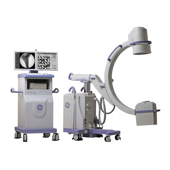
Page 45: Component Locator
System Overview 2.1.2. Component Locator 1. Image intensifier and CCD camera 2. Lateral rotation movement brake handle 3. Orbital movement brake handle 4. Skin spacer 5. X-ray tube head (X-ray tube and collimator) 6. Front wheel 7. Rear wheel 8. Wig-wag movement brake handle 9. - Page 46 Brivo OEC 850 Mobile C-Arm X-ray Product Service Manual 1. LCD Monitors 2. Keyboard 3. USB connector 4. Exposure indicator 5. Mouse 6. Cabinet for printer 7. DVD driver 8. Front wheels 9. Back wheels 10. Handles 11. Interface for DICOM and Video distributor...
-
Page 47: System Block
System Overview 2.2. System block... -
Page 48: System Schematics
Brivo OEC 850 Mobile C-Arm X-ray Product Service Manual 2.3. System Schematics... - Page 49 System Overview...
- Page 50 Brivo OEC 850 Mobile C-Arm X-ray Product Service Manual...
-
Page 51: Chapter3
Chapter3. Installation... -
Page 52: Overview
Brivo OEC 850 Mobile C-Arm X-ray Product Service Manual 3.1. Overview This chapter described the installation procedure of Brivo OEC 850 Mobile C-Arm X-ray Product. 3.2. Pre-Installation 3.2.1. Dimensions and Weights of System Dimensions: C-Arm: 181cm 76cm 175cm (71.3’’... -
Page 53: Environments
Installation Rated Continuous Line Current: 10A (220V/230V/240V) 12A (200V) 20A (100V/110V/120V) 16A power supply is required in China. And 20 A is required in Japan. NOTE Suitable sockets are required both in Scan room and Operating room for maintenance. Power supply should comply with requirement of the system power supply requirements. -
Page 54: Tools And Test Equipment
Stopwatch Network cable Printer paper or film Ruler longer than 12 inches (30cm) Digital volt-ohm meter or equivalent Special Tool Item Tool GE part number 9 inch Film cassette holder (if required) 5304073 Three copper sheets, each 1mm thick 00-877682-01... -
Page 55: Unpacking
Installation 3.3. Unpacking There are 2 packages for Brivo OEC 850 Mobile C-Arm X-ray Product. One is for C-Arm (L NOTE H=2000mm 900mm 1995mm. And the other is WorkStation (L H=1015mm 900mm 2150mm). - Page 56 Brivo OEC 850 Mobile C-Arm X-ray Product Service Manual Wood crowbar Accessory Stow-wood Loosen the screws and remove the wood support of image intensifier. Wood support Remove the baffle of the tube. Loosen the screws and remove the three fastening metal strips of the wheels. Fastening metal strip...
- Page 57 Installation Lift up one side of the C-arm with the wood crowbar and put the stow-wood under each rear wheel. Then loose all the screws and remove the wood fastening assembly on rear wheels of the C-arm. Hold the handles and move the C-arm backward to draw out backwards the image intensifier and tube.
- Page 58 Brivo OEC 850 Mobile C-Arm X-ray Product Service Manual Check parts according to packing list (refer to the packing list with the system for details). Before moving the system, please make sure the 4 brake handles: the C-Arm orbital rotation brake, the lateral rotation brake, the Wig-Wag brake, and the horizontal cross- WARNING arm brake are locked.
-
Page 59: Inspection
Installation 3.4. Inspection 3.4.1. Label Inspection After the system installation, check and verify that all labels in section 1.2.10 should be in position. Labels below should be in local language according to the regulation requirement. NOTE (Only exists when there’s laser aimer option) -
Page 60: External Inspection
Brivo OEC 850 Mobile C-Arm X-ray Product Service Manual 3.4.2. External Inspection 1. Cabling and Connector inspection Check the interconnect cable for damage or other problems. Verify that connector on cable mates well with the connector on C-Arm and that there are no bent or missing pins. Make sure the strain relief attaches securely to both the interconnect cable and connector. -
Page 61: Internal Inspection
Installation 3. Workstation Inspection Inspect each workstation component listed under the heading workstation inspection. Select one check box for each item in the list. WorkStation Inspection Physical Location No problem Loose or missing Broken or Chipped or found parts damaged parts scratched paint Monitor and Arm Keyboard and... -
Page 62: Setup
Brivo OEC 850 Mobile C-Arm X-ray Product Service Manual 3.5. Setup 3.5.1. Power Supply Adaption If your power supply is 100V/110V/115V/120V/127V/200V/230V/240V, please follow steps below to change power supply. Otherwise, go to section3.5.2. 1. Make sure that C-arm covers were removed. 2. -
Page 63: Ups
Installation 5. Install all the covers of the C-arm. 3.5.2. Follow these steps to setup the UPS. 1. Make sure that the rear cover and both lower side covers of workstation have been removed. 2. Plug the UPS battery connector. 3. - Page 64 Brivo OEC 850 Mobile C-Arm X-ray Product Service Manual 4. Press and hold UPS “test” button for several seconds to initiate a self-test. Release the button once the UPS sounds beeps. The workstation will start up. Wait until a message display: “Power failure! System will shut down immediately! Please check AC power and restart system later.”.
- Page 65 Installation 3-15...
-
Page 66: Power On
The auto fluoroscopy mode is selected and the power on indicator lights. The field size is in its maximum. The left monitor of workstation will display GE logo screen. The right monitor will enter into the PATIENT INFORMATION Screen automatically. -
Page 67: System Configuration
Installation 3.5.4. System Configuration Hold down Ctrl +Shift+Alt key and press ”E”, ”V”, ”R” keys orderly and quickly to invoke the service tool. 1. Input the service ID of the system. Refer to section 6.2.1. 2. Set the time zone. Refer to section 6.2.3. 3. - Page 68 Brivo OEC 850 Mobile C-Arm X-ray Product Service Manual C-arm Orbital Rotation When you release the orbital movement brake, place your other hand on the C-arm so CAUTION that you have control of the C-arm’s movement. 1. Release the orbital brake. 2.
- Page 69 Installation Steering 1. Verify that both rear casters respond appropriately to movement of the steering handle. 2. Verify that you can steer the rear casters 90 degrees to the left and 90 degrees to the right. 3. Verify that the casters track together when you steer them. 4.
- Page 70 Brivo OEC 850 Mobile C-Arm X-ray Product Service Manual Digital Spot Select digital spot via control panel. Take a digital spot shot and verify that fluoro exposure automatically terminates and image automatically saves to hard drive. Image Orientation Using the line pair tool as a phantom, take exposure in normal fluoro mode and verify the following functions: ...
- Page 71 Installation Alarm Reset Press and hold Alarm Reset key for approximately 2 seconds. Verify Fluoro time displayed on the C- arm control panel resets to zero. Radiographic Mode Select Radiography mode and verify that the indicator lights. C-arm key/X-ray switch test Perform the following test to verify that the system’s X-ray and key switches are operating satisfactorily.
-
Page 72: Workstation Checks
Brivo OEC 850 Mobile C-Arm X-ray Product Service Manual Emergency Switch Perform the following test to verify the emergency switch. 1. Press the emergency switch during raising C-arm. Emergency Switch 2. Verify that vertical column operation and exposure are disabled. 3. - Page 73 Installation 6. Verify ZOOM function ( ) displays a square region of interest (ROI) box and that you can magnify the ROI. 7. Verify NEGATE ( ) function reverses the light and dark values on the image displayed on the left monitor.
- Page 74 Brivo OEC 850 Mobile C-Arm X-ray Product Service Manual CD/DVD check 1. Place a blank CD or DVD in the in the CD/DVD drive and wait for the green LED on the front of the drive to turn off. 2. Press the Image Directory key ( ) on the keyboard to open the Image Directory.
- Page 75 Installation DICOM Check You can choose the verification items from DICOM worklist server, storage server and NOTE printer server, according to the customer’s network situation and equipment. 1. Remove the cable cover from the back cover of workstation. 2. Plug the network cable into the network connector on the computer. 3.
- Page 76 Brivo OEC 850 Mobile C-Arm X-ray Product Service Manual 5. Click “Network Config…”button. Input the “Station Name” and “AE Title”. The default AE Title is “OEC850”. You can change it according to the DICOM service’s requirement. Click “Config…”button and fill in the network information. You can obtain the information from network administrator. 6.
- Page 77 Installation 7. Select “DICOM Storage…” from the workstation setup screen. Click “Add…” button and fill in the information of the DICOM storage server. Obtain the information from network administrator. Click “OK” button to return to DICOM storage server list screen. Click “Verify” button.
- Page 78 Brivo OEC 850 Mobile C-Arm X-ray Product Service Manual Click “Add…” button and fill in the information of the DICOM printer server. Obtain the information from network administrator. Click “OK” button to return to DICOM printer server list screen. Click “Verify”...
- Page 79 Installation DICOM Worksheet Record Network Config information below: Station Name: Does this site use DHCP? Enter information into “Network Config” screen. AE Title: IP Address: Enter information into “Network Config” screen. Enter information into “Network Config” screen. Gateway: Enter information into “Network Config” screen. Subnet Mask: Enter information into “Network Config”...
- Page 80 Brivo OEC 850 Mobile C-Arm X-ray Product Service Manual Will the site use DICOM Worklist Server? If yes, record their configuration here. Worklist Server Server Alias: AE Title: IP Address: Gateway: Port Number: 3-30...
- Page 81 Installation Will the site use DICOM Storage Server? If yes, record their configuration here. Storage Server Server Alias: AE Title: IP Address: Gateway: Port Number: Modality 3-31...
- Page 82 Brivo OEC 850 Mobile C-Arm X-ray Product Service Manual Will the site use DICOM Printer Server? If yes, record their configuration here. Server Alias: AE Title: IP Address: Gateway: Port Number: Maximum: Minimum: Config. Info.: Border Density: BLACK WHITE Empty Density: BLACK WHITE Copies:...
- Page 83 Installation Will the site use DICOM Worklist Filter? If yes, record their option here. Get Today’s Exams: Enter information above in the “Schedule Filter” screen. The users will enter additional information on this screen. 3-33...
-
Page 84: Auto Technique Tracking
Brivo OEC 850 Mobile C-Arm X-ray Product Service Manual 3.6.3. Auto Technique Tracking Select Auto Fluoroscopy mode ( ), and the NORM field size to take an exposure. Put the copper filter on the tube head. Verify that the kVp changes accurately as copper filters are inserted into the field in the following ranges: Copper mm kVp range... - Page 85 Installation HLF dose rate check 1. Position the dosimeter in the center of the X-ray beam 30cm above the grid. Cover the image intensifier with lead thicker than 3mm for protection of the image intensifier. 2. Set kVp as 110kVp, increase mA to maximum in manual mode. Measure the dose rate while making exposure.
-
Page 86: Options Installation
Brivo OEC 850 Mobile C-Arm X-ray Product Service Manual 3.7. Options Installation 3.7.1. Laser Aimer Laser Aimer on Tube 1. Laser Aimer, which attaches to tube, is incorporated with the tube cover. Remove the standard tube cover. Position the tube cover with laser aimer and plug the power cable. Tighten the secure screws of the tube cover. - Page 87 Installation 5. Adjust the adjusters of the laser until the intersection of the laser beam is in the center circle of the beam alignment tool. (Use the circle to adjust the line to be vertical with the other and the screws to adjust the position of the line.) Circle adjuster 6.
- Page 88 Brivo OEC 850 Mobile C-Arm X-ray Product Service Manual Laser Aimer on Image Intensifier Perform the following procedure to install and operate the laser aimer on the Image Intensifier. The C- arm can be placed in any orientation that is convenient for attaching the laser aimer. There are no alignment marks or notches on the laser aimer that need to match any points on the image intensifier.
-
Page 89: Video Distributor
Installation 8. Functional check: Using fluoroscopy, verify that the cross-hair in the fluoro image, at the center of the area of interest. The location where the laser beam marks the patient corresponds to the center of the NOTE area of interest, indicated by the cross-hair in the fluoro image. Perform procedure below to remove the laser cover from the laser aimer: 1. - Page 90 6. Functional check: Power on the system. Check that the left monitor will display GE logo screen. Plug the left monitor video cable and connect to OUTPUT1 and OUTPUT2 respectively. Verify that the left monitor will display GE logo screen in each case. Then connect the video cable back to OUTPUT4 port.
- Page 91 Installation 8. Only 2 DVI output connectors are available for customer to use. First loose and remove 3 screws, and then remove the small cover. 9. Customer can connect the external monitor to OUTPUT1 or OUTPUT2 of video distributor. OUTPUT2 OUTPUT1 10.
-
Page 92: Printers
Brivo OEC 850 Mobile C-Arm X-ray Product Service Manual 3.7.3. Printers Brivo OEC 850 offers below printers as option. UP-990AD Thermal Printer UP-D897 Thermal Printer Please follow below steps to install the printers. Power off the system. Open the rear cover of the workstation. Plug one end of the USB cable to the video port of the printer. - Page 93 Installation Plug the USB cable into the USB port on computer. Cut off the other end of the power supply cable. Strip off 3 wire ends. Connect the wires to the terminal blocks at the bottom of the workstation (connect the L line (brown) to connector 1 or 2 or 3, N line (blue) to 6 or 7 or 8 and the ground line (yellow and green) to earth port.
-
Page 94: Film Cassette Holder
Brivo OEC 850 Mobile C-Arm X-ray Product Service Manual 3.7.4. Film cassette holder Please follow the steps below to install and remove the cassette holder: 1. Place the cassette holder over the face of the image intensifier with the handle opened out. 2. - Page 95 Installation 3. Fasten the DAP chamber to the adjustment set. Fasten the chamber set to the three studs with screws. 4. Place the DAP module on the metal block and tighten the 2 screws as below: DAP Module Chamber 5. Use socket to connect DAP cable and cable of chamber. 6.
- Page 96 Brivo OEC 850 Mobile C-Arm X-ray Product Service Manual Image of the adjustment tool (2) Fine tuning (Ensure the iris works normally before this procedure) Switch to the manual fluoro mode. Take exposure at high or middle kV (about 70kV). Meanwhile, make the iris in the field and adjust kV value to ensure the edges of the iris and circular tool are clear enough.
- Page 97 Installation Dose Test and Calibration Set Dosimeter as accumulative/maintenance. Put the detector of dosimeter on the axis of image intensifier and focus, 30 cm away from grid center. Clear the dosimeter. Create a new exam on workstation and ensure the DAP and dose show value on the workstation are cleared. Set kV/mA value as 110kV/4mA in manual fluoro mode.
-
Page 98: Skin Spacer
Brivo OEC 850 Mobile C-Arm X-ray Product Service Manual Dose value Dose measured value on Collimator field size kV/mA Error workstation dosimeter (mGy) (mGy) 60kv/1.3mA 45mm-43mm 110kv/4mA 60kv/1.3mA 110-120mm 110kv/4mA 60kv/1.3mA 140-150mm 110kv/4mA 60kv/1.3mA Largest size 110kv/4mA The field size in the form should be measured by BAFT. NOTE 3.7.6. -
Page 99: Two-Pedal Footswitch
Installation 3.7.7. Two-pedal Footswitch Brivo OEC 850 Mobile C-Arm X-ray Product provides a two-pedal footswitch as an option. Plug the cable of two-pedal footswitch to the socket on the right side of the C-Arm interface panel. Verify that the connector locks in place. Functional check: Power on the system. -
Page 100: Chapter4
Chapter4. Subsystem... -
Page 101: Power Distribution And Control
Brivo OEC 850 Mobile C-Arm X-ray Product Service Manual 4.1. Power Distribution and Control Power to main transformer is applied by pressing the Power ON key on the membrane control panel. Relay JR1 in PDU board energizes, then the relay JR1 and timer circuit in PDU board begin to work. The transformer will be powered by R1 and R2. - Page 102 Subsystem workstation IGBT Fan Boot Up IGBT Line Filter AC/DC Transformer TUBE AC24 Display BD AC220 DC24 (Boot up Section) DC+-15 (Filament Drive) Seal BD Main Transformer Display BD Membrane DC15/5 (Display Section) Panel AC220 DC3.3 Laser Aimer DC3.3 (Tube) DC+-15/5 Laser Aimer(I.I) Board...
- Page 103 Brivo OEC 850 Mobile C-Arm X-ray Product Service Manual AC220 Monitor1 AC220 Monitor2 Display adapter DC+-12/5 Frame Grabber AC220 ATX PS AC220 AC220 AC220 Interconnect Line Main BD Cable Filter SATA HD Control BD DC+-12/5 DVD-RW DC12 Protection Relay AC220 Video distributor USB Printer AC220...
-
Page 104: Mcb
Subsystem 4.2. MCB The MCB (Mainframe Control Board) is located in C-Arm mainframe and is the main control unit in mainframe. It is responsible for five functions. X-ray control: KV, mA and exposure control interfacing with collimator board, filament board, and KV control board Image chain control: control CCU and image intensifier User interface: key input and LED display interfacing with display board... - Page 105 Brivo OEC 850 Mobile C-Arm X-ray Product Service Manual For detailed circuit schematics of MCB, please refer to Appendix. MCB consists of 10 function blocks, which are illuminated as follows. MCB functional Block MCU function Read the registers of peripheral controller to get the status of sub-systems, such as getting the alarm status, etc.
- Page 106 Subsystem Peripheral controller function Sample the status of input pins, and record them into status registers polled by MCU Set output pins according to the control registers accessed by MCU Generate interrupt signal of alarm to MCU in order to request the processing Generate exposure control signals Check switch stuck error Control mAS control signals...
- Page 107 Brivo OEC 850 Mobile C-Arm X-ray Product Service Manual The external physical interfaces of MCB are defined in the table below: Connector Name Type Gender Description MCB digital DN41612 C All digital signals from/to other sub-system, such as signal connector Type Male collimator board, filament board, sealing board, CCU, KV control board etc.
- Page 108 Subsystem DB_INT. D44 lights on MCB when pressing button of control panel WK_Y & WK_Z. D45 on MCB lights normally, and flickers in communication EXPR D46 lights when EXPOSURE command is sent out Light lights when +3.3V is available Light lights when +15V is available Light lights when +5V is available Light lights when -15V is available Light lights when +24V is available...
-
Page 109: Display Board
Brivo OEC 850 Mobile C-Arm X-ray Product Service Manual POT: Reference Name Description POT1 IBS offset POT2 mAS signal gain POT4 MA-OFF mA control signal offset POT5 MA-GAIN mA control signal gain POT6 KV control signal gain POT7 MA-FB mA feedback gain 4.3. -
Page 110: Kv Control And Igbt Assembly
Subsystem SPI_/CS2 Chip select 2 for Digital 0/+15V 0V=enable MAX7301 YELLOW_LED Enable signal for Digital 0/+15V +15V=enable exposure LED on Control Panel POWER_OFF_COMMAND One termination of Passive POWER_OFF_COMMAND & power off relay POWER_OFF_RETURN connected means power off POWER_OFF_RETURN The other termination Passive command of power off relay... - Page 111 Brivo OEC 850 Mobile C-Arm X-ray Product Service Manual The inverter provides 40kHz AC power to monoblock. It can control kV value to follow the kV set value. There are two parts in the inverter: power converter and controller. Power converter consists of 1 AC-DC converter and 1 DC-AC converter. AC-DC converter includes rectifier bridge D and DC bus capacitor C1, C2.
- Page 112 Subsystem IGBT_ERROR_ALM IGBT error alarm Digital 0/+15V 0V=alarm DC_ERROR_ALM DC Power Bus Error alarm Digital 0/+15V 0V=alarm KV_UNBALANCE_ALM KV unbalance in two bridges of Digital 0/+15V 0V=alarm inverter. KV_FEEDBACK_OUTPUT KV sample value from KV control Analog 0-6V Unit board 20KV/V 4-13...
-
Page 113: Filament Control Board
Brivo OEC 850 Mobile C-Arm X-ray Product Service Manual 4.5. Filament Control Board Filament control board (MP4) can be separated to two parts simply, one is power unit and other is control unit. The power unit offers the energy to the filament transformer primary coil and the control unit control the energy input to the transformer by control the output voltage of the power unit. -
Page 114: Monoblock
Subsystem 1200Hz Clock of filament board Digital 0/+15V Used for filament drive signal (600Hz) generation Fluoro mA control Analog 3.0- signal 5.0V KV control signal Analog 4-12V Unit V/10KV 4.6. Monoblock Monoblock can generate X-ray. It mainly consists of high voltage generator and tube insert. All high voltage components are put into oil box, which can enhance the insulation performance. - Page 115 Brivo OEC 850 Mobile C-Arm X-ray Product Service Manual The tube is used to generate X-ray. This tube is a kind of double focus with fixed copper anode tube. It is suitable for oil insulation generator. Analog signals KV_GND and MA_CAT of sealing board are the anode and cathode of mA current signal respectively.
-
Page 116: X-Ray/Key Switches And Emergency Switch
Subsystem Anode Stationary Typical filament specification 4.2 V, 3.5A Maximum filament current 4.6A Weight 0.65 kg Nominal heat capacity 76kHU 4.7. X-ray/key Switches and Emergency Switch Key switch is used to control the unauthorized usage of X-ray exposure and vertical lift motor. Signals from Key switch to MCB: Name Description... - Page 117 Brivo OEC 850 Mobile C-Arm X-ray Product Service Manual Signals from Footswitch to MCB: Name Description Attribution Scale Comment FOOT-SWITCH Foot switch Passive Open/Close FOOT_SWITCH & REF_FOOT_SWT is termination connected means FOOT_SWITCH has pressed FOOT-SECURITY Foot security Passive Open/Close FOOT_SECURITY & REF_FOOT_SWT termination is connected means FOOT_SECURITY has pressed...
-
Page 118: Image Chain
Subsystem 4.8. Image Chain 4.8.1. Overview The following diagram the image chain pipeline of Brivo850. X-ray X-ray X-ray Detection Image Acquisition Image Processing Image Display Generation Collimator Analog Realtime Analog Digital Digital Video Video X-ray X-rays Collimat X-rays X-rays Light Camera Video Frame... - Page 119 Brivo OEC 850 Mobile C-Arm X-ray Product Service Manual 8 leafs Motorized iris collimator Shutter rotate angle: 180 degree The collimator is controlled by control panel through MCB and collimator control board (MP1). The function of the collimator control board is to control the iris and the Semi-transparent leaves of collimator.
-
Page 120: Image Intensifier
Subsystem Signals from MP1 to MCB are listed as follows. Name Description Attribution Scale Comment FSPO Feedback voltage from Iris position rheostat. Analog Reserved for pre- 5.6V view SRPO Feedback voltage from shutter rotation position Analog Reserved for pre- rheostat. 5.6V view SWPO... -
Page 121: Ccd/Ccu
Brivo OEC 850 Mobile C-Arm X-ray Product Service Manual 4.8.4. CCD/CCU N30_PWR20 NDR_ADV0 1 2 3 1 2 3 R101 R100 R79 R106 Parameter CODE DESCRIPTION Setup Criteria It is used to enable shading regulations SHADING J4 ON: position 1-2 ENABLE (J4 ON: position 1-2, J4 OFF: position 2-3) It is used to enable the Auto White Level. - Page 122 Subsystem Controls the KV control modality. J7: position 2-3 KV CONTROL J7-J8 MODALITY (J7-J8 UP/DOWN mode: position 1-2, J7-J8 J8: position 2-3 ANALOG mode: position 2-3) Adjust to get uniform SHADING R61-R52- Set the shading gain to compensate picture image with 1mm copper R47-R48 non-uniformity because of Image Intensifier.
- Page 123 Brivo OEC 850 Mobile C-Arm X-ray Product Service Manual CCD Head Connector DB9 Legend Command Description ND2 (PIN 1) Motor 2 Vcc (PIN 6) Power Supply 24Vcc ND1 (PIN 2) Motor 1 ROT (PIN 7) Rotation SCAN (PIN 3) Head test SYNC (PIN 4) Sync signal VIDEO (PIN 5)
- Page 124 Subsystem CCU Connector DB25 Legend ND FILTER AUTO OFF HALF GAIN NOT USED NOT USED NOT USED NOT USED NOT USED NOT USED INVH INVV FREEZE-A FREEZE-B X4 FILTER X16 FILTER X0 FILTER X8 FILTER 4-25...
- Page 125 Brivo OEC 850 Mobile C-Arm X-ray Product Service Manual NAME SIGNAL PIN DESCRIPTION GROUND REF. AUTOMATIC WHITE LEVEL. AUTO OPEN: ON LEVEL ON GND: OFF OUT= 0V IF DOSE IS CORRECT OR TOO HIGH. WITH JUMPER J7 AND J8 IN UP/DOWN MODE OUT= +18V IF DOSE IS TOO LOW.
-
Page 126: Image Grabber Card
Subsystem INVH OPEN: REAL IMAGE HOR. INV. GND: HORIZONTAL IMAGE INVERSION INVV OPEN: REAL IMAGE VERT. INV. GND: VERTICAL IMAGE INVERSION OPEN: LIVE IMAGE FREEZE-A GND: FREEZE THE IMAGE IN VIDEO A OPEN: LIVE IMAGE FREEZE-B GND: FREEZE THE IMAGE IN VIDEO B HALF GAIN INPUT (When it is present +5Vcc the gain of the CCD camera is reduced to HALF GAIN... -
Page 127: Computer And Peripheral
Brivo OEC 850 Mobile C-Arm X-ray Product Service Manual 4.9. Computer and Peripheral 4.9.1. Computer The computer mounted in the workstation takes over most of the communication with external devices and is the main device of workstation. The computer runs Linux system working with image grabber card and display card. -
Page 128: Dvd And Usb
Subsystem POWER_SECURITY_A One termination of relay Passive POWER_SECURITY_A & which indicates whether POWER_SECURITY_B power of workstation is connected means that on/off workstation is powered on POWER_SECURITY_A & POWER_SECURITY_B disconnected means that workstation is powered off POWER_SECURITY_B The other termination of Passive relay which indicates whether power of... -
Page 129: Keyboard And Mouse
Brivo OEC 850 Mobile C-Arm X-ray Product Service Manual 4.9.3. Keyboard and Mouse The keyboard contains a simple switch matrix for alphanumeric data. The keyboard connects to computer though PS2 interface. The following illustration shows the workstation keyboard. The mouse is an ambidextrous three-button optical wheel mouse that plugs into a PS2 port. 4-30... -
Page 130: Chapter5
Chapter5. Calibration... -
Page 131: Overview
Precision flat head screwdriver (3mm or less) to adjust camera iris, focus Transparent adhesive tape, with cutter (or need scissor or knife to cut the tape) Special Tool Item Tool GE part number Three copper sheets, each 1mm thick 00-877682-01 9-inch BAFT Tool 00-878105-02... -
Page 132: Kv Measurement And Adjustment
Calibration 5.2. kV Measurement and Adjustment 5.2.1. kV Measurement and Accuracy Check The X-ray generator is composed of high voltage transformer, high voltage rectifier and X-ray tube in one pressurized oil tank. kV value can be measured by kV meter. Position the kV meter in the center of the X- ray beam 30 cm above the focal spot. -
Page 133: Kv Adjustment
Brivo OEC 850 Mobile C-Arm X-ray Product Service Manual 5.2.2. kV Adjustment 1. Remove the C-arm console cover. Check the connection of IGBT board cables. 2. Remove the cover of PCB box. Extend MCB board with MCB extend board. Remove the J46 jumper on MCB extend board. - Page 134 Calibration 8. Test the voltage of TP16 on kV control board with multimeter. The voltage should be 3.15±0.05V. Otherwise, adjust R109. Clockwise rotation will decrease the voltage value and anticlockwise will increase the value. 9. Test the voltage of TP17 on kV control board with multimeter. The voltage should be 3.15±0.05V. Otherwise, adjust R110.
- Page 135 Brivo OEC 850 Mobile C-Arm X-ray Product Service Manual To next page...
- Page 136 Calibration...
- Page 137 Brivo OEC 850 Mobile C-Arm X-ray Product Service Manual kV control board...
-
Page 138: Ma Measurement And Adjustment
Calibration 5.3. mA Measurement and Adjustment 5.3.1. mA Measurement and Accuracy Check 1. Remove the cover of the C-arm console and the cover of PCB box. Extend MCB board with MCB extend board. 2. Remove the J46 jumper on MCB extend board. Connect the probes of ampere meter to TP222 (+) and TP210 (-) on MCB extend board. - Page 139 Brivo OEC 850 Mobile C-Arm X-ray Product Service Manual Take exposure at mA values below in manual normal fluoro mode. The Exposure mA_measure value should be between the minimum and maximum value in the form below. Otherwise, mA calibration procedure should be performed until all the mA_measure values meet the requirement in the list. Exposure mode mA value Setting mA_measure Minimum...
- Page 140 Calibration To next page 5-11...
- Page 141 Brivo OEC 850 Mobile C-Arm X-ray Product Service Manual 5-12...
-
Page 142: Ma Calibration
Calibration 5.3.2. mA calibration Refer to the drawings at the end of this section for the location of the points. Remove J46 jumper on MCB extend board. Connect the probes of ampere meter to TP222 (+) and TP210 (-) on MCB extend board in order to make the ampere meter in serial. - Page 143 Brivo OEC 850 Mobile C-Arm X-ray Product Service Manual 7. Take exposure at 80kV, 2mA. Measure TP7 (MA-SMP) on MCB board with oscilloscope. Set oscilloscope in TRIGGER mode and the trigger level is –250mV. The first pulse wave should be orthogonal and similar to the picture below: Otherwise, adjust POT4 on MP4 board.
- Page 144 Calibration MCB: To next To next page page 5-15...
- Page 145 Brivo OEC 850 Mobile C-Arm X-ray Product Service Manual POT5 5-16...
-
Page 146: Mas Measurement And Calibration
Calibration 5.4. mAs Measurement and Calibration 5.4.1. mAs Measurment and Accuracy Check Remove J46 jumper on MCB extend board. Connect the probes of ampere meter to TP222 (+) and TP210 (-) on MCB extend board. Connect the mAs meter to ampere meter in serial. Take exposure by the parameters below. -
Page 147: Beam Alignment And Image Calibration
Brivo OEC 850 Mobile C-Arm X-ray Product Service Manual 5. Set the kVp value to 80kVp and take an exposure for 3 minutes. 6. Wait for 5 minutes. Power off the system. 5.6. Beam Alignment and Image Calibration 5.6.1. Beam Alignment Setup Workstation Setup 1. - Page 148 Calibration BAFT Installation 1. Put the 9-inch BAFT (Beam Alignment Tool) on top of the Image Intensifier. 2. Orient the tool so that the number 1 and 2 on the BAFT tool is away from the mainframe, number 3 and 4 is on the Mainframe side. (See the picture below) 3.
- Page 149 Brivo OEC 850 Mobile C-Arm X-ray Product Service Manual 6. Align the BAFT tool to the circular optical field in the image as follows: a. Loosen the securing screws (4 screws for each horizontal and vertical adjustment). b. Adjust position adjustment screws (1 screw for each horizontal and vertical adjustment) on the BAFT tool.
-
Page 150: Camera Orientation
Calibration 5.6.2. Camera Orientation Camera Orientation Check 1. Create a new exam. 2. Set to Mag2 mode, and make an exposure. 3. Verify if the central square of the BAFT tool image is aligned with the vertical and horizontal lines of the display screen. -
Page 151: Camera Centering
Brivo OEC 850 Mobile C-Arm X-ray Product Service Manual 5.6.3. Camera Centering Camera Centering Verification 1. During a MAG 2 Fluoro exposure, use a Dry-Erase marker to make a dot on the left monitor at the center of the BAFT. 2. - Page 152 Calibration EMI Shield Securing Screw Camera Securing Screw EMI Shield Camera cable plug-in port is disassembled 3. Make sure that 4 Camera Alignment Screws are not too loose. If they are loose, tighten all 4 screws with modest torque. Camera Alignment Screws (there are 4 screws...
- Page 153 Brivo OEC 850 Mobile C-Arm X-ray Product Service Manual Camera Centering Example a. BAFT image center is not aligned with Rotation Center Marking. Need to Shift BAFT center to the SE (bottom right) direction. b. Shift the camera to the same direction to shift the BAFT image center, i.e., S.E. (South East, or bottom right) direction.
-
Page 154: Collimator Centering
Calibration 5.6.4. Collimator Centering Collimator Iris Centering Check / Calibration 1. Position the C-arm with Image Intensifier above the X-ray tube. 2. Create a new exam to make default settings. 3. Make Normal Fluoro exposures. Close the iris a bit to show the iris near the image boundary. - Page 155 Brivo OEC 850 Mobile C-Arm X-ray Product Service Manual Shutter Centering Check / Calibration 1. Close the collimator shutter to the smallest. 2. Select manual Fluoroscopy mode and take exposures. 3. Rotate the shutter and stop at vertical position during live exposure. 4.
-
Page 156: Field Size
Calibration 5.6.5. I.I. Field Size I.I. Field Size Verification 1. Select relative field size, open the collimator to the maximum, and take an exposure. 2. Read the BAFT tick mark on the boundary of the image. The size of the image should be within the range of the values below. -
Page 157: Limiting Field Size (Collimator Iris Field Size)
Brivo OEC 850 Mobile C-Arm X-ray Product Service Manual 5.6.6. Limiting Field Size (Collimator Iris Field Size) Limiting Field Size Verification 1. Create a new exam. 2. Load a film cassette in the BAFT. 3. Make sure the iris is opened completely. 4. - Page 158 Calibration 13. Repeat step 6 to step 12 for MAG1 and MAG2 field size. 14. If the requirements are not met, you must perform Limiting Field Size (Collimator Iris Field Size) Calibration. Limiting Field Size (Collimator Iris Field Size) Calibration 1.
-
Page 159: Abs Tracking Check And Adjustment
Brivo OEC 850 Mobile C-Arm X-ray Product Service Manual 5.6.7. ABS Tracking Check and Adjustment ABS Tracking Check 1. Make sure that X-ray tube cover is installed. 2. Position the C-arm with I.I. above the X-ray tube. 3. Select Auto Fluoroscopy mode, and the NORM field size to take an exposure. Put the 1mm, 2mm, and 3mm copper filter on the tube head. -
Page 160: Limiting Resolution
Calibration 7. Make an exposure to make sure the entrance dose rate 4.0mR/min (35.04 μGy/min or 2102 μGy/hr) as close as possible. Repeat as many time as necessary. Camera Iris CCW: Close Iris to increase dose rate CW: Open Iris to decrease dose rate Camera Focus 8. - Page 161 Brivo OEC 850 Mobile C-Arm X-ray Product Service Manual ~45 4. Select Auto Fluoroscopy mode. Take an exposure, and stop when image is stable. Adjust kVp and mA if necessary. 5. Read the limiting resolution on the display image. It is the maximum number (lp/mm) where half of the lines are distinguishable.
- Page 162 Calibration 3. Make an exposure, and check the resolution again. Repeat as many times as necessary. 4. If the resolution check still fails after many trials, proceed to I.I. Focus adjustment. Camera Iris Slowly turn CW or CCW Camera Focus Slowly turn CW or CCW Image Intensifier Focus Calibration I.I.
-
Page 163: Shading Correction
Brivo OEC 850 Mobile C-Arm X-ray Product Service Manual Cleanup 1. After passing, remove the resolution tool from the I.I. Grid. 2. Make sure to re-assembly of all components as the following: a. Power off the system. b. Assemble Camera Head Cover. c. - Page 164 Calibration 8. If you fail in step 5 or 6, proceed to Shading Correction. Shading Correction To prevent CCU/camera damage, make sure that you power off the system first when you CAUTION need to remove or insert the CCU power plug. 1.
- Page 165 Brivo OEC 850 Mobile C-Arm X-ray Product Service Manual <Warning> The following steps are strongly recommended to reduce the Radiation Hazard to the FSE. a. Position the C-arm so that the X-ray tube is directing away from the Mainframe. This is important to minimize the radiation hazard of the FEs.
-
Page 166: Dose Calibration
Calibration 15. Adjust contrast level 85 or higher, and make sure that the center region is not darker than the image boundary. Cleanup 1. Power off the system, and wait for complete shutdown. 2. Disconnect the cables from CCU. a. Disassemble the CCU from the Mainframe. b. -
Page 167: Lock And Unlock The Osd Menu
Brivo OEC 850 Mobile C-Arm X-ray Product Service Manual 5.8.2. Lock and unlock the OSD menu Action Key sequence Lock OSD menu (except hotkeys Press key Exit and Up Up Up in 3 seconds, if enabled) when keys are unlocked. Unlock OSD menu (except Press key Exit and Up Up Up in 3 seconds, hotkeys if enabled) - Page 168 Calibration Main Menu Function Adjustment range Description Adjustment of contrast This allows the brighter area to be seen more Contrast 0…255 distinctly. The center point is in 128 position. Note: for DVI-D signals the Contrast setting is optimized. Manual changes are not recommended. It is used to adjust the black level of the monitor.
-
Page 169: Software
Chapter6. Software... -
Page 170: Overview
Brivo OEC 850 Mobile C-Arm X-ray Product Service Manual 6.1. Overview Brivo OEC 850 Mobile C-Arm X-ray Product provides service tool in software for the service engineer. Using the service tool, service engineer can: Set service ID, language and time zone for system ... -
Page 171: Service Tool
Software 6.2. Service Tool After Brivo OEC 850 system boots up successfully, press down “Ctrl”, “Shift”, “Alt” keys together and press ”E”, ”V”, ”R” keys orderly and the service tool can be invoked. The service tool login screen will be displayed. -
Page 172: Service Id Setting
Brivo OEC 850 Mobile C-Arm X-ray Product Service Manual 6.2.1. Service ID Setting Click “Service ID Setting… “ button on the main screen to set or update service ID of the system. Current service ID is displayed on the screen automatically. Fill in the new service ID in the textbox. Then press “OK”... -
Page 173: Multi-Language Setting
Software 6.2.2. Multi-language Setting Click “Multi-Language Setting…” button on main screen to select the local language by country. 6.2.3. Time Zone Setting Click “ Time Zone…” button on main screen to set time zone for system. -
Page 174: Get System Information
Brivo OEC 850 Mobile C-Arm X-ray Product Service Manual 6.2.4. Get System Information Press “System information…” on main screen to get the system information, including: Version of workstation software Version of MCB software Number of saved exams in system ... -
Page 175: Exposure Management
Software 6.2.5. Exposure Management Select “Exposure Management…” on the main screen. The exposure management screen is displayed. Dose Group Setting Input Voltage 100V AC: Enable or disable “AC100V power” according to the AC power used. If AC 100V power is enabled, the Dose Group will be set as Normal 50 and HLF 50 automatically. This setting will be only selected when the input voltage is 100V AC, but it is inapplicable for 110V or 120V. - Page 176 Brivo OEC 850 Mobile C-Arm X-ray Product Service Manual The skin dose rate in the Dose Group represents the value for conditions of free-in-air irradiation at the patient skin: 30cm along the beam axis from the image intensifier surface. 1. Two dose groups in normal (standard) fluoro mode -Normal50: The skin dose rate does not exceed 50mGy/min in standard fluoro mode, such as Australia, Japan, New Zealand, etc.
- Page 177 Software Enable or disable X-ray termination function after 9’30’’ fluoro. If this function is enable, when the continuous fluoroscopy time reaches 9’30’’, X-rays will be terminated automatically. Refer to the following table “Exposure Management Matrix” to set Fluoro Alarm Control. ...
- Page 178 Brivo OEC 850 Mobile C-Arm X-ray Product Service Manual Auto-return Auto-return After 5min Terminate X- Countries / Dose Group Accessible Exposure After Without X- Ray After Regions Option Only In Auto Limit 20 Sec Exposure 9'30" Fluoro Normal 88 Brunei and HLF 100 Disable Disable Disable...
- Page 179 Software Auto-return Auto-return After 5min Terminate X- Countries / Dose Group Accessible Exposure After Without X- Ray After Regions Option Only In Auto Limit 20 Sec Exposure 9'30" Fluoro Normal 88 Georgia and HLF 100 Disable Disable Disable Disable Enable Normal 88 Germany and HLF 100 Disable...
- Page 180 Brivo OEC 850 Mobile C-Arm X-ray Product Service Manual Auto-return Auto-return After 5min Terminate X- Countries / Dose Group Accessible Exposure After Without X- Ray After Regions Option Only In Auto Limit 20 Sec Exposure 9'30" Fluoro Normal 88 Kuwait and HLF 100 Disable Disable Disable...
- Page 181 Software Auto-return Auto-return After 5min Terminate X- Countries / Dose Group Accessible Exposure After Without X- Ray After Regions Option Only In Auto Limit 20 Sec Exposure 9'30" Fluoro Normal 88 Oman and HLF 100 Disable Disable Disable Disable Enable Normal 88 Pakistan and HLF 100 Disable...
- Page 182 Brivo OEC 850 Mobile C-Arm X-ray Product Service Manual Auto-return Auto-return After 5min Terminate X- Countries / Dose Group Accessible Exposure After Without X- Ray After Regions Option Only In Auto Limit 20 Sec Exposure 9'30" Fluoro Normal 88 Spain and HLF 100 Disable Disable Disable...
-
Page 183: Database Backup And Restore
Software 6.2.6. Database Backup and Restore Click “Database Backup/Restore…” button to display the screen. You can backup the current database file on this screen. The database file contains patient and exam’s information. Click “Start backup…” button to save the current database file. A double confirm screen will pop up. -
Page 184: Set Imaging Defaults
Brivo OEC 850 Mobile C-Arm X-ray Product Service Manual 6.2.7. Set Imaging Defaults The service tool allows to set imaging parameters’ defaults. Click “Image Defaults…” on the main screen. Changes on Image Brightness, Image Contrast, Black/Wihte Margin and Sharpen power are not recommended because these values have been optimized for the image NOTE quality to compromise any anatolomical imaging. -
Page 185: Consistency Check
Software 6.2.8. Consistency Check The consistency check function is to check the consistency between the database and image files. Click “Consistency Check…” button on main screen to enter consistency check screen. Click “Check” button on the screen, and then click “Yes” button in confirmation screen to start the check process. -
Page 186: Image Import/Export
Brivo OEC 850 Mobile C-Arm X-ray Product Service Manual 6.2.9. Image Import/Export Service tool allows importing images from USB disk to local disk or exporting images from local disk to USB device. Brivo OEC 850 only supports USB disks in FAT or FAT32 format. NOTE 1. - Page 187 Software (1) Insert USB disk to USB interface. Click “Copy From” button to select USB devices to copy from. Choose the device in the USB list and click “OK”. Only those images, which are exported from Brivo OEC850 system, can be imported NOTE back.
- Page 188 Brivo OEC 850 Mobile C-Arm X-ray Product Service Manual 3. If you want to export images from local disk to USB, click export button on the screen. The screen will show local saved directory to copy from. (1) Click “Copy To” button. Select USB device as target destination to copy. Choose the device in the USB list and click OK.
-
Page 189: Log Viewer
Software 6.2.10. Log Viewer Log viewer screen allows service engineer to review the system log including the system event and detailed information of error, warning and information messages. Click “Log Viewer…” button on main screen. 1. Search Options: Enable to set the conditions to search. Date: Used to select the period to show the log. - Page 190 Brivo OEC 850 Mobile C-Arm X-ray Product Service Manual 3. Page Number Display the total and current page number of the log. Click the arrows to turn the pages. 4. Log Information Display the search results of the log. This field will show the error code, Type, sub-system, module, create date and log text of the log.
-
Page 191: Config File Export
Software 6.2.11. Config File Export The config file export screen allows service engineer to export system configuration files: IPConfig.xml: This file contains the parameter of image processing, including the setting values in “Image Defaults” screen. ServiceTool.xml: This file contains all the setting values in service tool except for image related. The export files will contain the current local setting values. -
Page 192: Restore Default
Brivo OEC 850 Mobile C-Arm X-ray Product Service Manual 6.2.12. Restore Default Click “Restore Default…” on main screen. Click “Delete” button will delete all database records and all images. Click “Delete” button will remove all patient information and all images. WARNING Click the “Clear”... -
Page 193: Software Installation And Upgrade
Software 6.3. Software Installation and Upgrade 6.3.1. Software Installation There are two software installation disks for Brivo OEC 850 C-Arm X-ray Product. One is the Operating System (OS) installation CD. The other is the Application CD. The OS installation CD should be installed prior to Application CD during the initial installation. - Page 194 Brivo OEC 850 Mobile C-Arm X-ray Product Service Manual 2. Type in “EVR850BJ”, then press “Enter” key. When the BIOS menu shows, use the arrow down button to select the “Advanced BIOS Features” and then press “Enter”. 6-26...
- Page 195 Software 4. Select “First Boot Device” and press “Enter”. Then choose the “CDROM” and press “Enter”. 6-27...
- Page 196 Brivo OEC 850 Mobile C-Arm X-ray Product Service Manual 5. Press the “ ” key and then press “Enter”. This will save your settings, and the system will reboot. (The system is now set to boot from CD ROM first.) 6-28...
- Page 197 Software 6. When the screen display “DISK BOOT FAILURE, INSERT SYSTEM DISK AND PRESS ENTER”, insert the OS installation CD into the CD/DVD drive of the WS, then press “Enter”. 7. Once you get to the prompt, type in “SG_EVR”. The OS software will then load on the system. 6-29...
- Page 198 Brivo OEC 850 Mobile C-Arm X-ray Product Service Manual 8. Once the software installation is complete, CD will be rejected automatically. Remove the CD and close the CD tray. Click the “reboot” button. 6-30...
- Page 199 Software 9. During the memory testing, press key on the keyboard to get to BIOS. 10. Type in “EVR850BJ” , then press “Enter” key. 11. When the BIOS menu shows, use the arrow down button and “Enter” key to select the “Advanced BIOS Features”...
- Page 200 Brivo OEC 850 Mobile C-Arm X-ray Product Service Manual 13. Press the “ “key and then press “Enter”. This will save your settings, and the system will reboot. (The system is now set to boot from hard disk first) 14. System will enter GDM desktop with a terminal pop up. 6-32...
- Page 201 Software Install Application Software 1. Insert the Application CD to CD/DVD drive of the workstation. Click “Run Command” in the warning message box. 2.The welcome screen will display. And the serial number of the system from the manufacture will be displayed automatically.
- Page 202 Brivo OEC 850 Mobile C-Arm X-ray Product Service Manual If the user data is detected on the workstation, the welcome screen will ask you to choose whether retain user data or not. 6-34...
- Page 203 Software If you want to retain user data, make Option 1 selected and enter OK. Select “Yes” to confirm your selection and start the Stage 1 process. Select “No” to return back the previous welcome screen. Select “Not retain the existing user data” will delete all existing data and it cannot be CAUTION recovered.
- Page 204 Brivo OEC 850 Mobile C-Arm X-ray Product Service Manual The Stage2 process will start automatically after reboot. If “Retain existing user data” option is selected restoring user data screen will display after the application packages installed. 6-36...
- Page 205 4. At the end of stage2, press “OK” to shut down the system. Functional test: Power on the system. The left monitor of workstation will display GE logo screen. The right monitor will enter into the PATIENT INFORMATION Screen automatically. Perform workstation operation check defined in section3.6.2.
-
Page 206: Application Software Upgrade
Brivo OEC 850 Mobile C-Arm X-ray Product Service Manual 6.3.2. Application Software Upgrade 1. Login service tool. Click “Upgrade” button on main screen. Preparation process screen will display. 2. After the preparation process the workstation will reboot. Error code will display on the control panel board when the system enter reboot process. NOTE Before login the system, Application CD should not be inserted. - Page 207 Software 3. Login the system with “root” account and the password is “install”. 4. System will enter GDM desktop with a terminal pop up. 5. Insert the Application CD to CD/DVD drive of the workstation. Click “Run Command” in the warning message box.
- Page 208 Brivo OEC 850 Mobile C-Arm X-ray Product Service Manual 6. The welcome screen will display. And the serial number of the system from the manufacture will be displayed automatically. Click “OK” button and the system will ask you to choose whether retain user data or not. If you want to retain user data, make Option 1 selected and enter OK.
- Page 209 Software 7. The stage1 of installation will start. The rest processes will be the same as the installation process including stage1 and stage 2. 6-41...
- Page 210 Brivo OEC 850 Mobile C-Arm X-ray Product Service Manual 8. After stage1 process complete, enter “OK” to reboot the workstation. 9. The Stage2 process will start automatically after reboot. 6-42...
- Page 211 Software If “Retain existing user data” option is selected restoring user data screen will display after the application packages installed. 10. At the end of stage2, press “OK” to shut down the system. Due to C-arm can’t shut down automatically after upgrade process completes, you should press shut down button on control panel manually.
- Page 212 Brivo OEC 850 Mobile C-Arm X-ray Product Service Manual Functional test: Power on the system. The left monitor of workstation will display GE logo screen. The right monitor will enter into the PATIENT INFORMATION Screen automatically. Perform workstation operation check in section3.6.2.
- Page 213 Software For German User German X-ray ordinance Roentgenverordnung (RöV) §16 and Qualitätssicherungs-Richtlinie (QS-RL) 3.1.3.8 require the SMPTE test pattern to be displayed on the system monitors for testing per Feb 2001 DIN V 6868-57. There is an exam, which patient name is "SMPTE test pattern" in the system image directory, providing the SMPTE test pattern image to be displayed on the system monitors for testing.
- Page 214 Brivo OEC 850 Mobile C-Arm X-ray Product Service Manual 3. Click “Image Import/Export…” button on main screen. The “Image Import& Export” screen will display. Click “Import…” button. 6-46...
- Page 215 Software 4. Insert USB disk to USB interface. Click “Copy From” button to select USB devices to copy from. Choose the device in the USB list and click “OK”. 5. Select the image and then click “Copy”. Click “Yes” button in confirmation screen to execute a copy operation.
- Page 216 Brivo OEC 850 Mobile C-Arm X-ray Product Service Manual 8. Click “Edit” button. Change the Last Name to “SMPTE test pattern” and delete the text in “First Name” and “M.I.” field. And then click “Exit” button. 9. Press the Image Directory key on the workstation keyboard.
-
Page 217: Troubleshooting
Chapter7. Troubleshooting... -
Page 218: Overview
Brivo OEC 850 Mobile C-Arm X-ray Product Service Manual 7.1. Overview This chapter describes messages that appear on the right workstation monitor during system operation. Messages may indicate any of the following: Information Warning Messages Error Messages When the error message appears, error code will also displayed on the kV, mA display field on control panel. - Page 219 Troubleshooting "Please turn the system off, wait 1 Invoking interface fails. minute, and then restart the system. 00004 Error If this message persists, call for service. Code:00004" "Please turn the system off, wait 1 Canceling thread fails. minute, and then restart the system. 00005 Error If this message persists, call for service.
- Page 220 Brivo OEC 850 Mobile C-Arm X-ray Product Service Manual "Please turn the system off, wait 1 Joining thread fails. minute, and then restart the system. 00013 Error If this message persists, call for service. Code:00013" "Please turn the system off, wait 1 Loading multi-language fails.
- Page 221 Troubleshooting “Please turn the system off, wait 1 UI activation fails. minute, and then restart the system. 00023 Error If this message persists, call for service. Code:00023” "Please turn the system off, wait 1 Serial port closedown fails. minute, and then restart the system. 00101 Error If this message persists, call for service.
- Page 222 Brivo OEC 850 Mobile C-Arm X-ray Product Service Manual Please turn the system off, wait 1 Loading library fails. minute, and then restart the system. 00501 Error If this message persists, call for service. Code:00501 Please turn the system off, wait 1 Lost frames.
- Page 223 Troubleshooting "Please turn the system off, wait 1 Loading grabber card config file fails. minute, and then restart the system. 00610 Error If this message persists, call for service. Code:00610" "Please turn the system off, wait 1 Loading IP config file fails. minute, and then restart the system.
- Page 224 Brivo OEC 850 Mobile C-Arm X-ray Product Service Manual "Please turn the system off, wait 1 CORBA communication error. minute, and then restart the system. 00901 Error If this message persists, call for service. Code:00901" "Please turn the system off, wait 1 Image data processing error.
- Page 225 Troubleshooting "Please turn the system off, wait 1 Waiting firmware fails. minute, and then restart the system. 01108 Error If this message persists, call for service. Code:01108" "Please turn the system off, wait 1 Software unlocking fails. minute, and then restart the system. 01109 Error If this message persists, call for service.
- Page 226 Brivo OEC 850 Mobile C-Arm X-ray Product Service Manual "Please turn the system off, wait 1 CPLD version incompatible. minute, and then restart the system. 01305 Error If this message persists, call for service. Code:01305" "Please turn the system off, wait 1 CPLD watch dog error.
- Page 227 Troubleshooting "Please turn the system off, wait 1 kV value is lower than 35KV. minute, and then restart the system. 01314 Error If this message persists, call for service. Code:01314" "Please turn the system off, wait 1 Bridges of inverter unbalance. Change minute, and then restart the system.
- Page 228 Brivo OEC 850 Mobile C-Arm X-ray Product Service Manual "Please turn the system off, wait 1 Communication with WKS RCC time minute, and then restart the system. out. 01323 Error If this message persists, call for service. Code:01323" "Please turn the system off, wait 1 Communication with WKS received minute, and then restart the system.
- Page 229 Troubleshooting "Please turn the system off, wait 1 No calibrated mA table for preheating minute, and then restart the system. the filament is found in flash. Create a 01332 Error calibrated mA table first. If this message persists, call for service. Code:01332"...
- Page 230 Brivo OEC 850 Mobile C-Arm X-ray Product Service Manual 10202 Warning DICOM operation fails. Code: 10202 DICOM association request fails. DICOM operation fails. Code: 10203 Association is rejected by DICOM 10203 Warning server. 10204 Warning DICOM operation fails. Code: 10204 Connection to DICOM server fails.
- Page 231 Troubleshooting 10504 Warning Reading image fails. Code: 10504 Reading image file fails. A software exception has occurred. Writing config file fails. 10505 Warning Code: 10505 A software exception has occurred. Writing image file writing fails. 10506 Warning Code: 10506 A software exception has occurred. Grabber capture thread's priority error Code: 10601 occurs.
- Page 232 Brivo OEC 850 Mobile C-Arm X-ray Product Service Manual A software exception has occurred. Resource files are damaged. Displayed Code: 10902 when a software exception occurred. 10902 Warning Click OK button to close the message. You can continue to take exposure. A software exception has occurred.
- Page 233 Troubleshooting administrator. Port number is invalid. Code: 11212 Port number is invalid. Obtain the 11212 Warning correct information from network administrator. Network configuration fails. Code: Network configuration fails. 11213 Warning 11213 There is invalid gateway setting in There is invalid gateway setting in 11214 Warning DICOM printer servers.
- Page 234 Brivo OEC 850 Mobile C-Arm X-ray Product Service Manual Can not detect UPS output. There is a Check UPS and connected cables. 11403 Warning potential risk of data loss. Code: 11403 UPS connection fails. There is a Check UPS and connected cables. 11404 Warning potential risk of data loss.
-
Page 235: Troubleshooting Guide
Troubleshooting 7.4. Troubleshooting Guide 7-19... - Page 236 Brivo OEC 850 Mobile C-Arm X-ray Product Service Manual Normal boot up process screen and control panel display: Workstation screen 2. Linux 1. BIOS 4. App 3. Linux Control Panel 2.MCB & WKS Comm and Exchange information 1.MCB Ready 3.Done Normal shut down process screen and control panel display: Normal Boot up time is 1’55”...
- Page 237 Troubleshooting 7-21...
- Page 238 Brivo OEC 850 Mobile C-Arm X-ray Product Service Manual 7-22...
- Page 239 Troubleshooting 7-23...
-
Page 240: Chapter8
Chapter8. Replacement... -
Page 241: Fru List
Brivo OEC 850 Mobile C-Arm X-ray Product Service Manual 8.1. FRU list Item Part number Description Quantity 5326480 PWA, COLLIMATOR CONTROL BOARD, EVR 5326484 PWA, MAINFRAME CONTROLLOR BOARD, EVR 5326475 PWA, FILAMENT CONTROL BOARD, EVR 5339933 ASM, IGBT INVERTER MODULE,EVR 5326487 PWA, kV CONTROL BOARD, EVR 5326482... - Page 242 Replacement Item Part number Description Quantity 5331651 Cable, 220V Power, EVR 5331599 MISC, DC POWER SUPPLY +24V AND +5V, EVR 5331598 MISC, DC POWER SUPPLY +15V, -15V AND +5V, EVR 5331606 MISC, BREAKER FOR 110V, EVR 5331605 MISC, BREAKER FOR 220V, EVR 5331596 MISC, START UP TRANSFORMER, EVR 5329283...
- Page 243 Brivo OEC 850 Mobile C-Arm X-ray Product Service Manual Item Part number Description Quantity 5343601 ASM, UNIVERSAL TRUCKLE WITH BRAKE, EVR 5336263 ASM, ONE PEDAL FOOTSWITCH, EVR 5331609 MISC, HAND SWITCH ASSY, EVR 5330849 MISC, EMERGENCY SWITCH, EVR 5325779 ASM, FRONT WHEEL, EVR 5333094 PLASTIC, SKIN SPACER 30CM,EVR 2418430...
- Page 244 Replacement Item Part number Description Quantity 5241505 DAP chamber, Dose_DAP measure, EverView7500 00-878105-02 9" BEAM ALIGHMENT TOOL ASSEMBLY ASM, LASER AIMER, 9 INCH ENGLISH WITH ALL LANGUAGES 5330473-01 SUPPLEMENT 5344737 ASM, DOUBLE FOOT SWITCH, EVR 5325571 Plastic, 9 inch II cover, EVR 5366466 Misc, UPS, EVR 5370278...
- Page 245 For the 8 parts as below, field engineer must ship the failed parts to Surgery engineering in NOTE China for autopsy in the first year after M3. Contact: Zhang Dounan GE HUALUN Medical Systems Co. Ltd No. 1 Yongchang North Road, Beijing Economic & Technological Development Area Beijing, P.R. China 100176 Tel: 8610-58068888...
- Page 246 Replacement 5332880 ASM, CONTROL PANEL, EVR After the replacement of the four parts below, please fill in the product locator card and mail it to local service operation office. Item Part Number Part Description 5325576 Generator, monoblock, EVR 5330059 Assembly, I.I with power supply, EVR 5336403 ASM COLLIMATOR EVR 5364175...
-
Page 247: Locations Of Fru
Brivo OEC 850 Mobile C-Arm X-ray Product Service Manual 8.2. Locations of FRU... - Page 248 Replacement...
- Page 249 Brivo OEC 850 Mobile C-Arm X-ray Product Service Manual 63(Right side cover) 63(Left side cover) 63 (Rear cover) 8-10...
-
Page 250: Replacement
Replacement 8.3. Replacement Electrical circuits inside the equipment use voltages that are capable of Causing serious injury or death from electrical shock. Use appropriate precautions. WARNING Please use specified fuse. If the system has power applied, power off the machine and unplug the AC power cord WARNING from the wall outlet. -
Page 251: Covers
Brivo OEC 850 Mobile C-Arm X-ray Product Service Manual 8.3.1. Covers Never allow anyone to use the system when any C-arm cover is removed. Use extreme caution if you intend to troubleshoot the equipment with the covers off and power WARNING applied. - Page 252 Replacement Workstation covers You must remove these workstation covers in the following sequence: 1. Rear Cover 2. Left and Right lower side covers 3. Front Cover 4. Left and right upper side covers Follow these steps to remove the workstation covers: 1.
- Page 253 Brivo OEC 850 Mobile C-Arm X-ray Product Service Manual 3. Remove the 2 screws on each side of the front cover and 2 screws in the upside of the printer cabinet as below. Remove the front cover. 4. Loose the screw and disassemble two workstation handles. 5.
- Page 254 Replacement Upper Covers Rear cover must be removed before upper covers can be removed. NOTE 1. Loose the screws and remove the monitor support cover. If the cover fit is tight, use two palms impulse upward on each side of the cover with moderate force continuously until the cover is pulled out.
- Page 255 Brivo OEC 850 Mobile C-Arm X-ray Product Service Manual 3. Loose the screws on the sheet metal. Then you can remove the sheet metal. 4. Remove all screws that secure the front top cover. And remove the front top cover. Replace the new top cover kits and install them in reverse sequence.
-
Page 256: Brake, Handle And Wheel
Replacement 8.3.2. Brake, Handle and Wheel Lateral Rotation Brake, Orbital Movement brake and Wig-Wag brake have the same replacement procedure: 1. Make sure the brake is set. 2. Loosen the screw that secures the handle to C-arm. 3. Remove the handle. 4. - Page 257 Brivo OEC 850 Mobile C-Arm X-ray Product Service Manual 6. Reassemble the covers of the cross arm. 7. Replace the new horizontal movement handle. Pay attention to keep the original assembling direction. 8. Place the handle in unlock position. Verify that you can push or pull the cross arm and lock the cross arm by placing the brake handle in lock position.
- Page 258 Replacement Rear wheel of the C-arm The FRU part for the rear wheel provides the 2 plates and cable pushers (P/N: 5333092). 1. Lift up the side of the C-arm carefully and keep the balance of the C-arm. Remove the label cover on the wheel plate.
- Page 259 Brivo OEC 850 Mobile C-Arm X-ray Product Service Manual Universal truckle of workstation The workstation has two kinds of the truckle: the universal truckle with brake (P/N: 5343601) and the universal without brake (P/N: 5343599). The FRU part contained the wheel and cable pusher. 1.
-
Page 260: Generator
Replacement 8.3.3. Generator 1. Remove the tube cover. 2. Unplug the cables connected to collimator. Unscrew the three screws that secured the collimator and remove it. 3. Disconnect the cables. Underlay the generator to prevent it from falling. Loosen the screws and replace the generator. -
Page 261: Collimator
Brivo OEC 850 Mobile C-Arm X-ray Product Service Manual 8.3.4. Collimator 1. Position the C-arm for easy access. Remove the tube cover. Loosen screws and replace the collimator. 2. Power on the system. 3. Select fluoroscopy mode and make sure to enable Automatic Technique. 4. - Page 262 Replacement Take off the Bridge Gear 15. Press the IRIS close Icon for more than 10s, and then adjust the resistor on the IRIS until the motor doesn’t rotate. Keep the motor resting and install the bridge well. 16. Select the manual fluoroscope mode and take exposure. Verify the IRIS field is at the center of the blanking circle.
-
Page 263: Pcbs
Brivo OEC 850 Mobile C-Arm X-ray Product Service Manual 8.3.5. PCBs Collimator control board (MP1 board) (P/N: 5326480) 1. Remove the rear cover of the console and the PCB box cover. 2. Take off the collimator control board (MP1 board) and insert a new one. 3. - Page 264 Replacement 3. Remove the MCB board and insert a new one. 4. Perform kV (section 5.2.2), mA (section 5.3.2) and mAs (section 5.4.2) calibration procedure in chapter 5. 5. Perform ABS Tracking check and adjustment (section 5.6.7) procedure in chapter 5. 6.
- Page 265 Brivo OEC 850 Mobile C-Arm X-ray Product Service Manual Mother board (P/N: 5326482) 1. Remove the rear cover of C-Arm console. 2. Unscrew the screws of PCB box cover and remove it. Remove the MP1, MCB and MP4 board. 3. Unscrew the screws and remove the PCB box. 4.
- Page 266 Replacement kV control board (P/N: 5326487) 1. Remove the rear cover of C-Arm console. 2. Unplug all cables connected to kV control board (KJ1, KJ2, KJ3, KJ4, KJ5, KJ6, KJ7). 3. Unscrew the four screws that secured the board. Replace the new kV control board. Connect all cables.
- Page 267 Brivo OEC 850 Mobile C-Arm X-ray Product Service Manual IGBT inverter module (P/N: 5339933) 1. Remove the rear cover of the C-arm console. 2. Loose the four screws and remove the shield cover. 3. Disconnect all cables connected to IGBT board and the cables to the fan. Remain the screws on the board as below after disconnect the cable.
- Page 268 Replacement Power Distribution Board (PDU) (P/N: 5326479) 1. Power off the system and disconnect C-arm’s AC plug from the AC receptacle. 2. Remove the covers of console. 3. Disconnect the cabling (PJ1, PJ3, PJ4, PJ5, PJ6, P1) from the PCB board. 4.
- Page 269 Brivo OEC 850 Mobile C-Arm X-ray Product Service Manual 8. The default power supply is AC 220V power input. If your power supply is 110V, adjust the jumpers (PJ9 and PJ10) according to wiring diagram. Refer to chapter 3.3 for details. 9.
- Page 270 Replacement UPS control board (P/N: 5370278) 1. Remove the rear cover of the workstation. 2. Disconnect all cables connected to UPS control board. 3. Loose the screws that secured the board. Remove the board and replace a new one. 4. Functional check: Power on the system. After the booting up process complete, unplug the AC power cord.
-
Page 271: Parts In Computer And Peripheral
Brivo OEC 850 Mobile C-Arm X-ray Product Service Manual 8.3.6. Parts in Computer and Peripheral Perform the procedures below to replace the parts of computer. 1. Remove the rear cover of the workstation. Unplug the cables from the computer. 2. Loosen the screws of the computer cover. Lift up and remove the cover. 3. - Page 272 Replacement Chassis Power Image Grabber card Mother board Display Card Memory Bank Hard disk Cut off the binding tie before removing the memory bank. And replace a new one to secure the memory bank after the replacement. NOTE Grabber card shall not be installed in the slot beside Display card. There are two hard disks in the computer.
- Page 273 Brivo OEC 850 Mobile C-Arm X-ray Product Service Manual Functional check: Power on the system. After login the Patient information screen, enter the patient information and verify that you can enter normally. Create a new exam and take exposure. Verify the system can work normally and the image will display on the left monitor.
-
Page 274: Exposure Indicator
Replacement 8.3.7. Exposure Indicator Perform the procedures below to replace exposure indicator: 1. Unscrew the 2 screws on the strip cover. Remove the strip cover. 2. Unplug the cable connected to the indicator. And then remove the four screws on the sheet metal support of the indicator. -
Page 275: Monitors
Brivo OEC 850 Mobile C-Arm X-ray Product Service Manual 8.3.8. Monitors To prevent monitor power lost, a binding is used to fix the monitor power plug (see the picture in step6). The binding is provided with the monitor FRU. Make sure the binding is CAUTION still used after the monitor replacement. - Page 276 6. Install the new monitor and reset all parts and cables. Make sure the binding is still used after the monitor replacement. Binding 7. Power on the system. The left monitor of workstation will display GE logo screen. The right monitor will enter into the PATIENT INFORMATION Screen automatically. Perform the brightness and contrast adjustment in section5.8 if necessary.
-
Page 277: Ccd Camera With Ccu
Brivo OEC 850 Mobile C-Arm X-ray Product Service Manual 8.3.9. CCD Camera with CCU Dangerous voltage levels are present when covers are removed from the C-arm. WARNING To prevent CCU/camera damage, make sure that you power off the system first when you CAUTION need to remove or insert the CCU power plug. - Page 278 Replacement Camera Alignment Screws (there are 4 screws with 90 degrees apart) 7. Remove the screws, which fasten the weight. And remove the weight. Pay attention to original mounting direction. 8. Remove 3 Camera fastening screws. And remove the old Camera from the I.I.. Pay attention to original mounting direction.
- Page 279 Brivo OEC 850 Mobile C-Arm X-ray Product Service Manual Step2. Replace CCU 1. Power off the system. Unplug the power cable. 2. Remove the Front and Rear Covers of the Mainframe. 3. Disconnect all the cables on the CCU (V3-FrameSync, CHB-Video, DB9, DB25, 24V Power). 4.
- Page 280 Replacement Parameter CODE DESCRIPTION Setup Criteria It is used to enable shading regulations SHADING ENABLE J4 ON: position 1-2 (J4 ON: position 1-2, J4 OFF: position 2-3) It is used to enable the Auto White Level. AUTO WTH J5 OFF: position 2-3 (J5 ON: position 1-2, J5 OFF: position 2-3) It is used to enable the Auto black Level.
- Page 281 Brivo OEC 850 Mobile C-Arm X-ray Product Service Manual 1. Disconnect DB 25 connector from the CCU. 2. Measure the average kV+ signal when measured directly on Pin1 port of DB25 to be –80~0mV without any X-ray shots. (Use horizontal precision of 10~50msec/div) ND FILTER AUTO OFF HALF GAIN...
-
Page 282: Image Intensifier With Power Supply
Replacement 8.3.10. Image Intensifier with power supply I.I. with Power Supply Perform the procedures below to replace the image intensifier with power supply (P/N: 5330059). 1. Position the C-arm for easy access. Remove the I.I. back cover. Remove CCD camera, EMI cover, weight and all cables according to the procedure in section 8.3.9. -
Page 283: Ups
Brivo OEC 850 Mobile C-Arm X-ray Product Service Manual 8.3.11. UPS 1. Remove the rear and front covers of the workstation. 2. Loose the screws that secured UPS assembly. 3. Disconnect the power cable connected to UPS. Use the handle to remove the UPS. 4. -
Page 284: Misc Parts
Replacement 7. Press and hold UPS “test” button for several seconds to initiate a self-test. The workstation will start up and enter BIOS. There will be a message to inform that there’s no AC power and need to shut down. 8. - Page 285 Brivo OEC 850 Mobile C-Arm X-ray Product Service Manual Drive Power transformer (P/N: 5329283) 1. Remove the rear cover of the C-arm. Remove the kV control board according to 8.3.5. 2. Cut off the binding tie. Disconnect the wires of the transformer, which are connected to J2. 3.
- Page 286 Replacement Start Up transformer (P/N: 5331596) 1. Remove the rear cover of the C-arm. Unscrew the three screws and open the package box. 2. Cut off the binding tie. Disconnect the wires of the transformer, which are connected to PDU board PJ4 and ground.
- Page 287 Brivo OEC 850 Mobile C-Arm X-ray Product Service Manual DC bus capacitor (P/N: 5329278) 1. Remove the rear cover of the C-arm. Unscrew the three screws and open the package box. The part is on the back of the package. There are two capacitors here but only one in FRU kit.
- Page 288 Replacement Breaker Brivo OEC850 provides 110V breaker (P/N: 5331606) and 220V breaker (P/N: 5331605). 1. Remove the rear cover and front cover of the C-arm. Unplug the cable connected to the circuit breaker. 2. Loose the screws and remove the breaker. Then replace a new breaker. 3.
- Page 289 Brivo OEC 850 Mobile C-Arm X-ray Product Service Manual The other is on the base near the breaker. You should remove the rear and front covers of the C-arm console first. Connect the cable according to the schematic on the filter: After the replacement, power on the system and take exposure.
- Page 290 Replacement Workstation Power filter (P/N: 5331607) 1. Remove the workstation rear cover. Remove the UPS control board first. Workstation power filter 2. Unplug the cable connected to the filter. 3. Loose the screws and remove the filter. Replace a new part and connect the cable according to the schematic on the filter.
- Page 291 Brivo OEC 850 Mobile C-Arm X-ray Product Service Manual Interconnect cable type P/N: 5331655; 2 type P/N: 5416178; 3 type P/N: 5435248) The three kinds of interconnect cable are defined as FRU. Please note that refer NOTE corresponding part number to order appropriate interconnect cable. P/N: 5331655 P/N: 5416178 P/N: 5435248...
- Page 292 Replacement Power on the system. Verify that the Workstation and C-Arm complete software booting up and initialization with no errors reported on their displays. Shut down the system and verify the system can shut down normally. Grid (P/N: 5330066) Loose the screws and remove the grid. Replace a new one. Notice the two white dot marks on the grid for the direction.
-
Page 293: Linear Actuator
Brivo OEC 850 Mobile C-Arm X-ray Product Service Manual Fuse, Fast-Acting, Ampere F5, F6, F7, F8, 5398500 5326482 PWA, mother board, EVR Rating-0.5A,Voltage Rating- 250V,5x20 mm Fuse, Fast-Acting, Ampere 5398501 5326482 PWA, mother board, EVR Rating-0.1A,Voltage Rating- 250V,5x20 mm Fuse, Fast-Acting, Ampere 5398502 5326482 PWA, mother board, EVR... - Page 294 Replacement 3. Remove the screws of the cross arm cover and remove the cover. 4. Loose the screws and remove the rear plate. Remove the pin in the shaft. 5. Put something (Wood strip or other kind of support) under console to prevent the whole base to tilt backward.
- Page 295 Brivo OEC 850 Mobile C-Arm X-ray Product Service Manual 7. Use something (for example, wood bar) to block up the C-arm. And put something on ground and on left of base (for example, cardboard). Overturn the C-arm console to left side. 8.
- Page 296 Replacement 10. Open the package box. Remove the screws on the top end of external column, and remove the side cover. Remove the plug on inner column. Screw a M4 screw (Length is more than 25 mm) into the screw hold on actuator upper pin and draw the pin out. 11.
- Page 297 Brivo OEC 850 Mobile C-Arm X-ray Product Service Manual 13. Insert the pin with M4 screw into the hole and check if the pin is in the axis of the linear actuator. Unscrew the M4 screw and tighten the plug on the hole. Lock the pin on the bottom of the linear actuator and put the cover back.
-
Page 298: Switch
Replacement 8.3.14. Switch Hand switch (P/N: 5331609) 1. Remove the rear and front cover of the C-arm console. Disconnect the cable from the hand switch. 2. Loose the screw that secured the hand switch cable. 3. Remove the hand switch and replace a new one. 4. - Page 299 Brivo OEC 850 Mobile C-Arm X-ray Product Service Manual 2. Loose the screws and remove the base and switch. Then replace a new one. 3. Power on the system. Press the emergency switch, vertical column operation will cease and X- rays will be disabled.
-
Page 300: Others
Replacement 8.3.15. Others Please refer to chapter3 for the replacement of these FRU parts. Part Number Part Description Section Number 5333060 Cable, 110V Power, EVR 3.5.1 5331651 Cable, 220V Power, EVR 3.5.1 5333094 PLASTIC, SKIN SPACER 30CM,EVR 3.7.6 2418430 Component, UP-D897 Thermal Printer, EVR 3.7.3 5330067 Component, UP-990AD Thermal Printer, EVR... - Page 301 Brivo OEC 850 Mobile C-Arm X-ray Product Service Manual Part#_Cable Item Country Part#_Plug Plug Type Voltage with plug Belgium 2415149 CEE7 230V Bolivia 2415149 CEE7 230V Bosnia 2415149 CEE7 220V Brazil 5407039 NBR 14136 127V Brazil 2415149 CEE7 220V Brunei 5399116 BS 1363A 240V...
- Page 302 Replacement Part#_Cable Item Country Part#_Plug Plug Type Voltage with plug Iraq 5399115 BS 546 230V Iraq 2415149 CEE7 230V Iraq 5399116 BS 1363A 230V Ireland 5399116 BS 1363A 230V Israel 5407050 SI-32 220V Italy 2415149 CEE7 230V Jamaica 5408318 NEMA 5-15P 110V Japan 5407035...
- Page 303 Brivo OEC 850 Mobile C-Arm X-ray Product Service Manual Part#_Cable Item Country Part#_Plug Plug Type Voltage with plug Panama 5408318 NEMA 5-15P 120V Paraguay 2415149 CEE7 220V Peru 2415149 CEE7 220V Poland 2415149 CEE7 230V Portugal 2415149 CEE7 230V Romania 2415149 CEE7 230V...
-
Page 304: Chapter9
Chapter9. Periodic Maintenance... -
Page 305: Overview
Serious injury and property damage can result from incorrectly performed service procedures. Observe all operating and safety procedures in this document. Procedures should be performed by service personnel specifically trained by GE Healthcare WARNING do Brasil Comércio e Serviços para Equipamentos Médico-Hospitalares LTDA to calibrate the Brivo OEC 850 C-Arm and Workstation. - Page 306 Periodic Maintenance Electrical Shock This system can generate lethal voltages. Practice safe electrical testing procedures WARNING when performing periodic maintenance procedures. After taking X-rays, the high voltage cables can retain a lethal charge, even if you power down the system. Even though the contacts are recessed, high voltages can arc several WARNING inches from their terminals if the cables are removed from the connector wells.
-
Page 307: Tools And Test Equipment
Precision flat head screwdriver (3mm or less) to adjust camera iris, focus Transparent adhesive tape, with cutter (or need scissor or knife to cut the tape) Special Tool Item Tool GE part number Three copper sheets, each 1mm thick 00-877682-01 9-inch BAFT Tool 010-878105-02... -
Page 308: Pm Checklist
Periodic Maintenance 9.2. PM Checklist Brivo OEC 850 PM Checklist Administrative Information Medical Facility Information Field Service Engineer Information Hospital or Clinic Name: FSE name: Address: City: Employee SSO: State: Country: Postal Code/Zip: Contact Person: Installation Date: Contact Phone: Department: System Configuration Workstation Software Version: MCB Software Version:... - Page 309 Brivo OEC 850 Mobile C-Arm X-ray Product Service Manual Field Size and Image Check Field Size Verification Mag Mode NORM(210 ±10) MAG1(157 ±8) MAG2 (119 ±8) Displayed Image Diameter (mm) Auto Technique Tracking Image Resolution Copper Filters Specification Measured Adjustment Mag Mode Specification Measured...
-
Page 310: Administrative Information
Periodic Maintenance 9.3. Administrative Information Medical Facility Information: Enter all information about the medical facility where the system is installed. Field Service Engineer Information: Enter Field Service Engineer name, Region ID number and Employee ID number. System Configuration: Complete each field in the System Configuration section. This section identifies specific information about the system being maintained. -
Page 311: Footswitch Cable And Pins
Brivo OEC 850 Mobile C-Arm X-ray Product Service Manual 9.4.4. Footswitch cable and pins Inspect footswitch cable and verify that the cable, connector and pins are not damaged. 9.4.5. Ground Continuity Perform the ground continuity test described below. Do not perform this continuity test with the AC plug connected to a power receptacle. WARNING Verify continuity between the following: From... -
Page 312: System Function Checks
Periodic Maintenance 9.6. System Function checks Check the following areas of the C-Arm and workstation for proper operation. 9.6.1. Perform Power On Checks Observe safety procedures when operating motorized features. WARNING Perform the following steps with the system powered up and normally booted. 1. - Page 313 Brivo OEC 850 Mobile C-Arm X-ray Product Service Manual C. Collimator semi-transparent leaves rotate. 4. Press kVp and mA keys and verify that the technique can be adjusted manually. 5. Press and hold ALARM RESET key for approximately 2 seconds. Verify fluoro time displayed on the C-arm control panel resets to zero.
- Page 314 Periodic Maintenance 2. Place X-ray keyswitch in XRAYOFF position ( ). Press handswitch and verify that no X-rays are generated. Press vertical lift button and verify the vertical lift column is operational. 3. Place X-ray keyswitch in ON position ( ).
-
Page 315: Workstation Checks
Brivo OEC 850 Mobile C-Arm X-ray Product Service Manual 9.6.3. Workstation Checks Mechanical Movement Refer to 3.6.2 for workstation mechanical movement check. Adjust the monitor movement annually: 1. Loose the screws and remove the monitor support cover. If the cover fit is tight, use two palms impulse upward on each side of the cover with moderate force continuously until the cover is pulled out. - Page 316 Periodic Maintenance 6. Verify ZOOM ( ) function displays a square region of interest (ROI) box and that you can magnify the ROI. 7. Verify NEGATE ( ) function reverses the light and dark values on the image displayed on the left monitor.
-
Page 317: X-Ray Generator Accuracy Tests
Brivo OEC 850 Mobile C-Arm X-ray Product Service Manual 9.7. X-ray Generator Accuracy Tests These tests measure the kVp accuracy of the system. Complete the X-ray Generator Accuracy section. 9.7.1. kVp Accuracy Refer to section5.2.1 for kVp accuracy check. 9.7.2. mA Accuracy Refer to section5.3.1 for mA accuracy check. -
Page 318: Image Resolution
Periodic Maintenance 9.8.3. Image Resolution Using the Converging line pairs/millimeter (lp/mm) tool on the Image Intensifier. Verify the resolution in lp/mm is equal to, or greater than the following values: Mag Mode NORM MAG1 (6’’) MAG2 (4.5’’) (9’’) (Field Size) Resolution (lp/mm) ≥... - Page 319 Brivo OEC 850 Mobile C-Arm X-ray Product Service Manual Dose Accuracy Test According to the collimator field size settings, adjust the collimator opening size by beam alignment tool. In each opening size test, create a new exam on the workstation. Set the exposure parameters as 45kV, 1.3mA in manual fluoro.
-
Page 320: Reporting
Periodic Maintenance 9.10. Reporting 9.10.1. Install Equipment Covers Install all equipment covers you removed earlier. Make sure all air filters are clean and properly attached to the covers. 9.10.2. Complete PM Comments Write any comments important to the PM procedure in the Comments section of the PM Checklist. 9-17... -
Page 321: Chapter10. Technical Reference
Chapter10. Technical Reference... -
Page 322: Overview
The policy of GE Healthcare is one of continual product development and improvement. For this reason, GE Healthcare reserves the right to change the operating characteristics and specifications of newer products at any time, without prior notice, and without incurring any obligation relating to previously manufactured items. -
Page 323: Power Requirements
Technical Reference 10.2.3. Power Requirements Voltage: AC 100V/110V/120V/200V/220V/230V/240V Frequency: 50Hz/60Hz±3Hz Rated Momentary Line Current (shorter than 5s): 25A (220V/230V/240V) 30A (200V) 50A (100V/110V/120V) Rated Continuous Line Current: 10A (220V/230V/240V) 12A (200V) 20A (100V/110V/120V) Maximum impedance: 0.6 Ω/0.3 Ω 16A power supply is required in China. -
Page 324: Physical Specifications
Brivo OEC 850 Mobile C-Arm X-ray Product Service Manual 10.2.6. Physical Specifications C-Arm 10-4... - Page 325 Technical Reference 39.2’’ (100cm) Horizontal travel 8’’ (20cm) Vertical travel 16’’ (40cm) Orbital rotation 120°(90°/30°over scan) Lateral rotation ±205° Wig-Wag 25°(±12.5°) Weight 245±10kg Workstation Weight: 140±10kg Option Weight 0.22±0.02kg Skin Spacer 0.17±0.02kg Laser Aimer (tube) 0.65±0.06kg Laser Aimer (Image Intensifier) 2.16±0.2kg Film Cassette holder 1.4±0.1kg...
-
Page 326: Specification Of Key Components
Brivo OEC 850 Mobile C-Arm X-ray Product Service Manual 10.3. Specification of Key Components 10.3.1. X-Ray Generator Nominal electric power 2.0kw (100kV, 20mA, 0.1s) Maximum electric power Normal Fluoro 440W 660W Digital Spot 1320W Radiography 2.2 kW High frequency generator 40kHz Voltage 40kV~110kV, step value: 1kV... -
Page 327: X-Ray Tube
Technical Reference Value of mAs 1.0, 1.3, 1.6, 2.0, 2.5, 3.2, 4.0, 5.0, 6.3, 8.0, 10, 13, 16, 20, 25, 32, 40, 50, 63, 80 mAs Pulse Fluoro 1/2/4/8pps The lowest Current Time Product or the 40kVp, 1mAs combination of Loading Factors 10.3.2. -
Page 328: X-Ray Tube Assembly
Brivo OEC 850 Mobile C-Arm X-ray Product Service Manual Large focal spot 1.4 mm Anode Stationary Typical filament specification 4.2 V, 3.5A Maximum filament current 4.6A Weight 0.65 kg Anode cooling rate 37 kHU/min Anode heat capacity 76kHU Manufacturer LOHMANN MODEL 110/3DF Maximum voltage between anode and... -
Page 329: Collimator
Technical Reference 10.3.4. Collimator Input power: DC 6V, 0.9W Electrical connection mode: through DB9. Mechanical connection mode: cast aluminum bracket, screw fitting Fluoroscopy Nominal diameter circle: 23/15/11cm (9”/6”/4.5”) X-Ray beam continuously adjustable to an area of less than 5×5 cm at the image receptor Radiography Nominal diameter circle: 23cm (9”) 10-9... -
Page 330: Others
Brivo OEC 850 Mobile C-Arm X-ray Product Service Manual 10.3.5. Others Semi-transparent shutters Rotation 180° Operation Controlled on panel Grid Type Circular Material Carbon fiber Lines/cm Ratio 10:1 Focus distance 100 cm Image Intensifier Type 3 Fields 2 Fields 1 Fields Input field size 9’’(23 cm) 6’’(15cm) -
Page 331: Tube Rating Chart
Technical Reference 10.4. Tube Rating Chart The following charts and data describe tube characteristics when operated with three-phase full-wave rectification, a reasonable approximation to the high frequency generator with minimal ripple. 10.4.1. Filament Emission Characteristics Small Focal Spot 10-11... - Page 332 Brivo OEC 850 Mobile C-Arm X-ray Product Service Manual Large Focal Spot 10-12...
-
Page 333: Single Load Ratings
Technical Reference 10.4.2. Single Load Ratings Small Focal Spot Exposure time in seconds 10-13... - Page 334 Brivo OEC 850 Mobile C-Arm X-ray Product Service Manual Large Focal Spot Exposure time in seconds 10-14...
-
Page 335: Thermal Characteristic
Technical Reference 10.4.3. Thermal Characteristic Anode Heating and cooling characteristics: Tube Housing heating and cooling characteristic: Joules 800 000 300W 200W 640 000 480 000 320 000 160 000 Time (minutes) 10-15... -
Page 336: Radiation Safety Specification
Brivo OEC 850 Mobile C-Arm X-ray Product Service Manual 10.5. Radiation Safety Specification Operators are strongly urged to be familiar with the current recommendations from the International Commission on Radiological Protection. (ICPR) Take radiation protection of the patient and operator into consideration seriously. Scatter data in this manual is only for reference. -
Page 337: Scatter Radiation Specification
Technical Reference 10.5.2. Scatter radiation specification 10-17... -
Page 338: Material Safety Data Sheets
Brivo OEC 850 Mobile C-Arm X-ray Product Service Manual 10.6. Material Safety Data Sheets Manufacturer’s Material Safety Data Sheets are available from the manufacture upon request. Contact the following manufacturers with regard to the materials listed: Sinkiang Kelamayi Lubricating Oil Plant Address: Jinlong Town Youlong Road No. - Page 339 Appendix...
- Page 340 Brivo OEC 850 Mobile C-Arm X-ray Product List Name Part Number Total Pages Revision Filament Board (MP4) 5326475 UP/Down Driver Board 5326476 Power Distribution Board 5326479 Mother Board 5326482 Extended Board 5326483 Collimator Control Board (MP1) 5326480 Mainframe Control Board 5326484 Display Board 5326486...
- Page 341 Circuit Schematics Appendix- 3...
- Page 342 Brivo OEC 850 Mobile C-Arm X-ray Product Appexdix-4...
- Page 343 Circuit Schematics Appendix- 5...
- Page 344 Brivo OEC 850 Mobile C-Arm X-ray Product Appexdix-6...
- Page 345 Circuit Schematics Appendix- 7...
- Page 346 Brivo OEC 850 Mobile C-Arm X-ray Product Appexdix-8...
- Page 347 Circuit Schematics Appendix- 9...
- Page 348 Brivo OEC 850 Mobile C-Arm X-ray Product Appexdix-10...
- Page 349 Circuit Schematics Appendix- 11...
- Page 350 Brivo OEC 850 Mobile C-Arm X-ray Product Appexdix-12...
- Page 351 Circuit Schematics Appendix- 13...
- Page 352 Brivo OEC 850 Mobile C-Arm X-ray Product Appexdix-14...
- Page 353 Circuit Schematics Appendix- 15...
- Page 354 Brivo OEC 850 Mobile C-Arm X-ray Product Appexdix-16...
- Page 355 Circuit Schematics Appendix- 17...
- Page 356 Brivo OEC 850 Mobile C-Arm X-ray Product Appexdix-18...
- Page 357 Circuit Schematics Appendix- 19...
- Page 358 Brivo OEC 850 Mobile C-Arm X-ray Product Appexdix-20...
- Page 359 Circuit Schematics Appendix- 21...
- Page 360 Brivo OEC 850 Mobile C-Arm X-ray Product Appexdix-22...
- Page 361 Circuit Schematics Appendix- 23...
- Page 362 Brivo OEC 850 Mobile C-Arm X-ray Product Appexdix-24...
- Page 363 Circuit Schematics Appendix- 25...
- Page 364 Brivo OEC 850 Mobile C-Arm X-ray Product Appexdix-26...
- Page 365 Circuit Schematics Appendix- 27...
- Page 366 Brivo OEC 850 Mobile C-Arm X-ray Product Appexdix-28...
- Page 367 Circuit Schematics Appendix- 29...
- Page 368 Brivo OEC 850 Mobile C-Arm X-ray Product Appexdix-30...
- Page 369 Circuit Schematics Appendix- 31...
- Page 370 Brivo OEC 850 Mobile C-Arm X-ray Product Appexdix-32...
- Page 371 Circuit Schematics Appendix- 33...
- Page 372 Brivo OEC 850 Mobile C-Arm X-ray Product Appexdix-34...
- Page 373 Circuit Schematics Appendix- 35...
- Page 374 Brivo OEC 850 Mobile C-Arm X-ray Product Appexdix-36...
- Page 375 Circuit Schematics Appendix- 37...
- Page 376 Brivo OEC 850 Mobile C-Arm X-ray Product Appexdix-38...
- Page 377 Circuit Schematics Appendix- 39...
- Page 378 Brivo OEC 850 Mobile C-Arm X-ray Product Appexdix-40...
- Page 379 Circuit Schematics Appendix- 41...
- Page 380 Brivo OEC 850 Mobile C-Arm X-ray Product Appexdix-42...
- Page 381 Circuit Schematics Appendix- 43...
- Page 382 Brivo OEC 850 Mobile C-Arm X-ray Product Appexdix-44...
- Page 383 Circuit Schematics Appendix- 45...
- Page 384 Brivo OEC 850 Mobile C-Arm X-ray Product Appexdix-46...
- Page 385 Circuit Schematics Appendix- 47...
- Page 386 Brivo OEC 850 Mobile C-Arm X-ray Product Appexdix-48...
- Page 387 Circuit Schematics Appendix- 49...
- Page 388 Brivo OEC 850 Mobile C-Arm X-ray Product Appexdix-50...
- Page 389 Circuit Schematics Appendix- 51...
- Page 390 Brivo OEC 850 Mobile C-Arm X-ray Product Appexdix-52...
- Page 391 Circuit Schematics Appendix- 53...
- Page 392 Brivo OEC 850 Mobile C-Arm X-ray Product Appexdix-54...
- Page 393 Circuit Schematics Appendix- 55...
- Page 394 Brivo OEC 850 Mobile C-Arm X-ray Product Appexdix-56...
- Page 395 Circuit Schematics Appendix- 57...
- Page 396 Brivo OEC 850 Mobile C-Arm X-ray Product Appexdix-58...
- Page 397 Circuit Schematics Appendix- 59...
- Page 398 Brivo OEC 850 Mobile C-Arm X-ray Product Appexdix-60...
- Page 399 Circuit Schematics Appendix- 61...
- Page 400 Brivo OEC 850 Mobile C-Arm X-ray Product Appexdix-62...
- Page 401 Circuit Schematics Appendix- 63...
- Page 402 Brivo OEC 850 Mobile C-Arm X-ray Product Appexdix-64...
- Page 403 Circuit Schematics Appendix- 65...
- Page 404 Brivo OEC 850 Mobile C-Arm X-ray Product Appexdix-66...
- Page 405 Circuit Schematics Appendix- 67...
- Page 406 Brivo OEC 850 Mobile C-Arm X-ray Product Appexdix-68...
- Page 407 Circuit Schematics Appendix- 69...
- Page 408 Brivo OEC 850 Mobile C-Arm X-ray Product Appexdix-70...
- Page 409 Circuit Schematics Appendix- 71...
- Page 410 Brivo OEC 850 Mobile C-Arm X-ray Product Appexdix-72...
- Page 411 Circuit Schematics Appendix- 73...
- Page 412 Brivo OEC 850 Mobile C-Arm X-ray Product Appexdix-74...
- Page 413 Circuit Schematics Appendix- 75...
- Page 414 Brivo OEC 850 Mobile C-Arm X-ray Product Appexdix-76...
- Page 415 Circuit Schematics Appendix- 77...
- Page 416 Brivo OEC 850 Mobile C-Arm X-ray Product Appexdix-78...
- Page 417 Circuit Schematics Appendix- 79...
- Page 418 Brivo OEC 850 Mobile C-Arm X-ray Product Appexdix-80...
- Page 419 Circuit Schematics Appendix- 81...
- Page 420 Brivo OEC 850 Mobile C-Arm X-ray Product Appexdix-82...
- Page 421 Circuit Schematics Appendix- 83...
- Page 422 Brivo OEC 850 Mobile C-Arm X-ray Product Appexdix-84...
- Page 423 Circuit Schematics Appendix- 85...
- Page 424 Brivo OEC 850 Mobile C-Arm X-ray Product Appexdix-86...
Need help?
Do you have a question about the Healthcare Brivo OEC 850 and is the answer not in the manual?
Questions and answers