Table of Contents
Advertisement
Quick Links
Advertisement
Table of Contents

Related Manuals for Palfinger INTERLIFT ILFP 40


Summary of Contents for Palfinger INTERLIFT ILFP 40
- Page 1 OWNER’S MANUAL ILFP 30, 3000 lbs. Capacity ILFP 40, 4000 lbs. Capacity 01/24...
- Page 2 Copyright © 2023 Palfinger Interlift, LLC. All rights reserved. Information in this document is subject to change without notice. Visit www.palfinger.com for up to date information and notifications. If you received this product with damaged or missing parts, contact INTERLIFT Liftgates at (888)-774-5844 Parts Order/Inquiries liftgateparts@palfinger.com...
-
Page 3: Table Of Contents
Owner’s Manual ILFP 30/40 Table of Content Manual Updates ........................6 Important Notes ........................7 Attention ........................7 Important Notes ......................7 General Information ..................... 8 Safety Information ......................... 10 Basic Parts in Detail ......................12 General View of Liftgate ..................... 12 Circuit Board Connector Cables ................. - Page 4 Owner’s Manual ILFP 30/40 8.2.2.1 Control board wiring and connector setup ........32 8.2.2.2 Control board plug setup..............33 8.2.2.3 Control board wiring and connector setup (Easy move model) ..34 8.2.2.4 Control board plug setup (Easy move model) ......... 35 8.2.3 Hydraulic Schematic ..................
- Page 5 Owner’s Manual ILFP 30/40 Company Information: Company Name: Advisor Name: Vehicle Year Make & Model: Liftgate Information: Liftgate Serial Number: Liftgate Model Number: Date of Purchase: Date of Installation: Thank you for choosing INTERLIFT Liftgates. Rev. 1.6...
-
Page 6: Manual Updates
Owner’s Manual ILFP 30/40 Manual Updates Revision Description • Changed the logos, from Palfinger to Interlift v1.6 Rev. 1.6... -
Page 7: Important Notes
Owner’s Manual ILFP 30/40 Important Notes Attention Before starting any operations of the liftgate, please read and understand this OWNER’S MANUAL. Its intention is to act as a guide for the operation personal as well as to give help with preventive maintenance but does not take place of unauthorized usage or repair by unqualified personnel. -
Page 8: General Information
Owner’s Manual ILFP 30/40 The electric supply is taken from the vehicle battery. If the vehicle battery is not sufficient or not existing (like on trailer units), an auxiliary battery kit needs to be installed. The electric control power is protected via a 20 Amp fuse and an on-off switch. - Page 9 Owner’s Manual ILFP 30/40 4. Do not overload. See the Rating Label on the unit for the rated load. Remember that this limit applies to both raising and lowering operations. 5. Each load should be placed in a stable position as near as possible to the body of the truck/trailer. 6.
-
Page 10: Safety Information
Owner’s Manual ILFP 30/40 Safety Information This manual follows the Guidelines set forth in “ANSI Z535.4-2007” for alerting you to possible hazards and their potential severity. ! DANGER indicates an imminently hazardous situation which, if not avoided, will result in death or serious injury. - Page 11 4) Call INTERLIFT Liftgates for assistance in the USA at 888-774-5844. You can also contact INTERLIFT Liftgates by fax (562) 924-8318, or on the internet- www.PALFINGER.com If you are facing any problems or are in need of repair, contact INTERLIFT Liftgates for information regarding experienced and trained Authorized Service Center in your area.
-
Page 12: Basic Parts In Detail
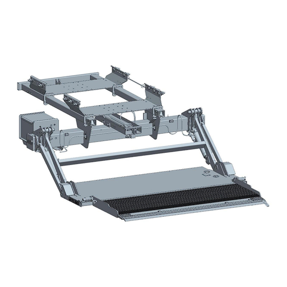
Owner’s Manual ILFP 30/40 Basic Parts in Detail General View of Liftgate Slider Rails Swing fixture Push-Pull Cylinder Liftarm Lift cylinder Foot control Aux. Battery kit Parallel arm Coil springs Folding assist Main section (steel) Cart stops Tip section (aluminum) Figure 1: ILFP Slide lift Rev. -
Page 13: Circuit Board Connector Cables
Owner’s Manual ILFP 30/40 Circuit Board Connector Cables Description Part No. PC- board K plus P-200 7193UK Cover with hinge - for control system P-200 7474 Clamp for cover P-201 0169 Wire harness for control box (J30+J32) P-200 7410 Wire harness for power pack (J1) P-201 0018 Wire harness for circuit board power (J1+J2) P-200 7406... -
Page 14: Control Box
Owner’s Manual ILFP 30/40 Control Box Description Part No. Control box with PC-board and harness P-200 9304 Control box with cable (without PC-board) P-200 7415 Complete outer plastic box P-200 9205 Operation label ATG-ILUK Flip down lid P-200 7476 Momentary turn knob P-200 7456 Contact block P-200 7457... -
Page 15: Maximum Load And Placing Of Load On Platform
Owner’s Manual ILFP 30/40 Maximum Load and Placing of Load on Platform All INTERLIFT Liftgates are rated up to a maximum load. The point of maximum load is rated at a defined distance. The center point of maximum load is at 30” for all ILFP lift gates from start of Truck or Trailer Body, as shown in Figure 2. -
Page 16: Operation Of Liftgate
Owner’s Manual ILFP 30/40 Operation of Liftgate Before use: All lift gate functions can be controlled with the 3-button control box, which is mounted on the curb side of the truck or trailer. NOTE: Never slide platform in or out with load on the platform. Operating the ILFP with Control Box 1. -
Page 17: Operating The Ilfp With The 3-Button Flush Mounted Control
Owner’s Manual ILFP 30/40 Operating the ILFP with the 3-Button flush mounted control 1. Turn on the liftgate with the on/off switch located in the cab(trucks) or at the rear end of the trailer 2. Lowering down By pushing the bottom button the lift gate will lower down from its storage position. -
Page 18: Operating The Ilfp With The 3-Button Flush Mounted Control (Easy Move Model)
Owner’s Manual ILFP 30/40 Operating the ILFP with the 3-Button flush mounted control (Easy move model) 1. Turn on the liftgate with the on/off switch located in the cab (trucks) or at the rear end of the trailer 2. Automatically lower and slide out the liftgate Push the two bottom buttons to automatically lower and slide out the gate completely until the gate hits the slide stops... -
Page 19: Operation By Hand Held Remote Control
Owner’s Manual ILFP 30/40 Operation by Hand Held Remote Control Hand Controls are NOT weatherproof and are designed to be stored inside bodies in holsters or in weatherproof boxes. Female Receptical (Looking at Front) Button No. 1 → UP Button no. 2 → DOWN Figure 4: Hand Held Remote Control with Plug &... -
Page 20: Preventive Maintenance And Quick Check
Owner’s Manual ILFP 30/40 Preventive Maintenance and Quick Check The ILFP needs preventive maintenance to perform at its fullest capability. Lubricate and inspect regularly. Also, check that all details are not damaged, e.g. Hoses, cables, controls, etc. REPAIR OR REPLACE IMMEDIATELY FAULTY PARTS Maintenance and Care The following inspection and maintenance should be performed at the recommended intervals depending on operation and amount of cycles or at the time when the unit shows any signs of damage or abuse. -
Page 21: Trailer To Tractor Connection Test
Owner’s Manual ILFP 30/40 Trailer to Tractor Connection Test CROSS TEST ON ENTIRE CHARGE SYSTEM SINGLE POLE PLUG SET UP a 12 Volt lead from tractor coil cord b Center (+) plug on front of trailer c Trailer ground on front of trailer d Tractor chassis ground Testing of full system using a battery load tester: Start with testing each individual battery on both tractor and trailer before proceding... -
Page 22: Lubrication
Owner’s Manual ILFP 30/40 Lubrication Properly lubricated, the INTERLIFT Liftgates ILFP model will ensure longevity. Therefore, lubricate the lift at the same time as the truck/trailer. Grease more frequently if the liftgate is heavily used. The liftgate should be greased every 500 cycles (depending on use – estimated every 3 month). Check the oil level in the tank. -
Page 23: Figure 5: Lube Points
Owner’s Manual ILFP 30/40 Oil Change on Power Pack Figure 5: Lube Points Location of Grease Zerks (8 on each side, 16 total) Oil level in the power pack tank (see marking inside of power pack reservoir) Platform hinges, Slide Rails and optional Cart Stops (use WD-40 spray for lubrication) Rev. -
Page 24: Checking And Changing The Oil
Owner’s Manual ILFP 30/40 7.3.2 Checking and Changing the Oil Check the quality of hydraulic fluid. Take the following steps to change the oil. In stored position, lower gate to ground (for Easy move model keep gate in stored position) and remove lock bolt. Pull the power pack out until you can reach the oil filler cap. -
Page 25: Decal Placement And Inspection
Owner’s Manual ILFP 30/40 Decal Placement and Inspection For operator’s safety, all decals appearing in “Decal Kit” must be in a conspicuous place on control side of liftgate to be read by operator. This is typically a combination of decals on the liftgate and truck body. - Page 26 Owner’s Manual ILFP 30/40 The picture below will help you to place all decals visible in order to get maximum operational safety. Decal - A Decal - L Decal - C Decal - B Decal - F Decal - H Decal - G Rev.
-
Page 27: Quick Check List
Owner’s Manual ILFP 30/40 Quick Check List 1. Operate the liftgate throughout its entire operation and check for noise and damage such as bent parts or cracked welds. 2. Inspect all welds and fasteners that attach the mount frame to the truck. All pins and bolts that connect the lift arm to the mount frame and to the platform. -
Page 28: Troubleshooting
Owner’s Manual ILFP 30/40 Troubleshooting ATTENTION: Dangerous injuries possible from tools short circuiting main battery connections. Every time you are finished troubleshooting, close the rubber cover on the curbside of the mount frame. REINSTALL THE PLASTIC STRAP ON THE RUBBER COVER WHEN FINISHED!! Please check the following points before looking for faults: •... -
Page 29: Basic Function Check
Owner’s Manual ILFP 30/40 Basic Function Check 8.1.1 LIFTGATE is competely DEAD (No Clicking or Movement at all) 1. Check the ON-OFF switch. To activate and start operating the ILFP you will have to turn on the ON-OFF switch. 2. Check the circuit breaker at the main batteries. Every truck has a circuit breaker on top of the main battery. -
Page 30: On-Off Switch On, But All Functions Are Dead
Owner’s Manual ILFP 30/40 In the Hydraulic Power Unit next to the motor you will find two fuses. Check for burned fuses and replace with the same type (15 amp) if necessary. DO NOT use higher amperage fuses. Replace fuse when Open this cap to check the fuses metal bridge is broken 5. -
Page 31: Electrical And Hydraulic Schematic
Owner’s Manual ILFP 30/40 Electrical and Hydraulic Schematic 8.2.1 Main Wiring Diagram Liftgate Mount Frame Main Truck Batteries Circuit Breaker To Ignition Switch Ground Battery Ground Isolator Main (if applicable) Circuit Disconnect Breaker Aux. Batteries (if applicable) applicable) (Third Battery Shown for heavy applications Only) Ground Circuit breaker MUST be fastened securely... -
Page 32: Electrical Schematics
Owner’s Manual ILFP 30/40 8.2.2 Electrical Schematics 8.2.2.1 Control board wiring and connector setup Figure 1 Control board wiring schematic Rev. 1.6... -
Page 33: Control Board Plug Setup
Owner’s Manual ILFP 30/40 8.2.2.2 Control board plug setup FOOT CONTROL GROUND for PC BOARD CONTROL PANEL CAB ON-OFF SWITCH TRUCK SLIDE VALVES JUMPER POWER PACK on Trailer WIRELESS CONTROL CYLINDERS POSITIVE for PC BOARD LIFT 15 (2 ea) PUSH-PULL (black #2 to 2 CYLINDERS and black # 4 to 27) -
Page 34: Control Board Wiring And Connector Setup (Easy Move Model)
Owner’s Manual ILFP 30/40 8.2.2.3 Control board wiring and connector setup (Easy move model) Figure 3 Electrical schematic Easy move Rev. 1.6... -
Page 35: Control Board Plug Setup (Easy Move Model)
Owner’s Manual ILFP 30/40 8.2.2.4 Control board plug setup (Easy move model) WARNING FOOT LIGHTS CONTROL GROUND for PC BOARD CONTROL PANEL JUMPER SLIDE VALVES POWER PACK WIRELESS CONTROL Easy move Proximity Switch CYLINDERS POSITIVE for PC BOARD LIFT 15 (2 ea) PUSH-PULL (black #2 to 2 CYLINDERS... -
Page 36: Hydraulic Schematic
Owner’s Manual ILFP 30/40 8.2.3 Hydraulic Schematic Functions: Lift: M+S1+S2 Lower: S1+S2+S5+S11 Slide Out: M+S8 Slide In: M+S7 S1, S2 on lift cylinder and S7, S8 on push pull valve block are double acting release valves: They have to be activated for fluid to go through them in either direction To slide out S8 is activated to allow fluid to both sides of retractable cylinders To slide in S7 is activated to allow fluid to piston rod side of retractable cylinders Datum... -
Page 37: Functional Description Of Hydraulics When Operating
Owner’s Manual ILFP 30/40 Functional Description of Hydraulics when Operating The description in the following chapters are relating to Figure 11 “Hydraulic Schematic”. Please use this drawing to understand the specific functionality of the ILFP lift gate. 8.3.1 Slide Out Function •... -
Page 38: Ilfp Push-Pull Valving
Owner’s Manual ILFP 30/40 ILFP Push-Pull Valving J42-81 J1-12 J42-80 Figure 52 Valve block setup at main frame Rev. 1.6... -
Page 39: Needed Information For Ordering Spare Parts And Repairs
Owner’s Manual ILFP 30/40 Needed Information for Ordering Spare Parts and Repairs Ordering Spare Parts In order to assure quick delivery of spare parts, please always state the following information when making orders: Lliftgate model & serial number. Designation and number of the spare part in accordance with the spare parts list. Designation and number marked on the individual component (if available). -
Page 40: Warranty
Owner’s Manual ILFP 30/40 Warranty INTERLIFT Liftgates provides warranty as part of its conditions of delivery. Spare part deliveries are first of all billed. INTERLIFT Liftgates then issues credit for all or part of the invoiced sum, when INTERLIFT Liftgates has been able to determine that the warranty claim is justified as defined by its warranty conditions. -
Page 41: Contact Address
Owner’s Manual ILFP 30/40 Contact Address 15939 Piuma Ave Cerritos, CA 90703 Phone: (562)-924-8218 Fax: (562)-924-8318 E-mail (parts order): liftgateparts@palfinger.com E-mail (technical support): technicalapplications@palfinger.com 572 Whitehead Road Trenton, NJ 08619 Phone: (609)-587-4200 Fax: (609)-587-4201 E-mail (parts order): liftgateparts@palfinger.com E-mail (technical support): technicalapplications@palfinger.com...
Need help?
Do you have a question about the INTERLIFT ILFP 40 and is the answer not in the manual?
Questions and answers