Table of Contents
Advertisement
Quick Links
Advertisement
Table of Contents

Related Manuals for Palfinger INTERLIFT ILQ 22


Summary of Contents for Palfinger INTERLIFT ILQ 22
- Page 1 OWNER’S MANUAL ILQ 22, 2200 lbs. Capacity 01/24...
- Page 2 Copyright © 2023 Palfinger Interlift, LLC. All rights reserved. Information in this document is subject to change without notice. Visit www.palfinger.com for up to date information and notifications. If you received this product with damaged or missing parts, contact INTERLIFT Liftgates at (888)-774-5844 Parts Order/Inquiries liftgateparts@palfinger.com...
-
Page 3: Table Of Contents
Owner’s Manual ILQ 22 Table of Contents Manual Updates ..................... 5 Important Notes ..................... 6 Attention ..................... 6 Important Notes ..................6 General Information ..................7 Safety Information....................9 Basic Parts in Detail ..................... 11 General View of Liftgate ................11 Circuit Board Connector Cables ............... - Page 4 Owner’s Manual ILQ 22 Needed Information for Ordering Spare Parts and Repairs ......35 Ordering Spare Parts ................35 Repairs ..................... 35 Warranty ....................... 36 Contact Address ....................37 Table of Figures Figure 1: ILQ Cantilever ....................11 Figure 2: Center Point of Load ....................13 Figure 3: Load Diagram (ILQ 22) ....................
-
Page 5: Manual Updates
Company Information: Company Name: Advisor Name: Vehicle Year Make & Model: Liftgate Information: Liftgate Serial Number: Liftgate Model Number: Date of Purchase: Date of Installation: 1. Manual Updates Revision Description • Changed the logos, from Palfinger to Interlift v1.4 Rev. 1.4... -
Page 6: Important Notes
Owner’s Manual ILQ 22 Important Notes Attention Before starting any operations of the liftgate, please read and understand this OWNER’S MANUAL. Its intention is to act as a guide for the operation personal as well as to give help with preventive maintenance but does not take place of unauthorized usage or repair by unqualified personnel. -
Page 7: General Information
Owner’s Manual ILQ 22 The electric supply is taken from the vehicle battery. If the vehicle battery is not sufficient, an auxiliary battery kit needs to be installed. The electric control power is secured via a 20 Amp fuse and an on-off switch located inside the cab. - Page 8 Owner’s Manual ILQ 22 4. Do not overload. See the Rating Label on the unit for the rated load. Remember that this limit applies to both raising and lowering operations. 5. Each load should be placed in a stable position as near as possible to the body of the truck/trailer. 6.
-
Page 9: Safety Information
Owner’s Manual ILQ 22 Safety Information This manual follows the Guidelines set forth in “ANSI Z535.4-2007” for alerting you to possible hazards and their potential severity. ! DANGER indicates an imminently hazardous situation which, if not avoided, will result in death or serious injury. - Page 10 4) Call INTERLIFT Liftgates for assistance in the USA at 888-774-5844. You can also contact INTERLIFT Liftgates by fax (562) 924-8318, or on the internet- www.PALFINGER.com If you are expecting difficulty or are in need of repair, contact INTERLIFT Liftgates for information regarding experienced and trained Authorized Service Center in your area.
-
Page 11: Basic Parts In Detail
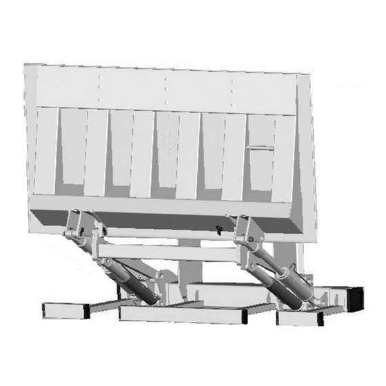
Owner’s Manual ILQ 22 Basic Parts in Detail General View of Liftgate 3 Button Hand control Mount frame Tilt Cylinder Serial Tag Lift Arm Lift Cylinder 3 Button Flush Mount Control Rear bumper Circuit Board Center of Gravity of (behind cover) maximum load Platform Hydraulic Power... -
Page 12: Circuit Board Connector Cables
Owner’s Manual ILQ 22 Circuit Board Connector Cables Description Part no. Sensor B13 for lift arm (J41) P-1332476 Cable for solenoid valve (J4) P-67254198 PC- board K1 plus P-2015340 Cover for control system P-2007474 Wire harness for control box (J30) P-2007295 Wire harness for hand control (J31) P-2008921... -
Page 13: Maximum Load And Placing Of Load On Platform
Owner’s Manual ILQ 22 Maximum Load and Placing of Load on Platform Every INTERLIFT Liftgate is rated up to a maximum load. The point of maximum load is rated at a defined distance. The center point of maximum load is at 24” from start of Truck or Trailer Body, as shown in Figure A = Distance from Truck Body to the Center Point of Load on the Platform Truck or Trailer... -
Page 14: Operation Of Liftgate
Owner’s Manual ILQ 22 Operation of Liftgate Turn Control switch to “ON”, the L.E.D.’s will light up inside the cab. All lift gate functions Before use: can be controlled with the 3-button flush mount control, which is mounted on the curb side of the truck or trailer. -
Page 15: Operation By Hand Held Remote Control
Owner’s Manual ILQ 22 Operation by Hand Held Remote Control 1. LOWERING DOWN: Push button number 3 2. LIFTING UP: Push button number 1 Tilt functions: Push button number 2 while lifting or lowering 1. TILT DOWN: Push button 2 and 3 at the same time TILT FUNCTION 2. -
Page 16: Application Of The Liftgate For Dock Loading
Owner’s Manual ILQ 22 Application of the Liftgate for Dock Loading → Move platform under the ramp and apply a cantilever drive-over dock plate (Fig. 4). Always chock the wheels using Dock Loading If not possible, there are other ways of loading: •... -
Page 17: Preventive Maintenance And Quick Check
Owner’s Manual ILQ 22 Preventive Maintenance and Quick Check The ILQ needs preventive maintenance to perform at its fullest capability. Lubricate and inspect regularly. Also, check that all details are not damaged: Hoses, cables, controls, etc. REPAIR OR REPLACE IMMEDIATELY FAULTY PARTS Maintenance and Care The following inspection and maintenance should be performed at the recommended intervals depending on operation and amount of cycles or at the time when the unit shows any signs of damage or abuse. -
Page 18: Lubrication
Owner’s Manual ILQ 22 Lubrication Properly lubricated, the ILQ INTERLIFT Liftgate will ensure longevity. Therefore, lubricate the lift at the same time as the truck/trailer. Grease more frequently if the liftgate is heavily used. The liftgate should be greased every 1200 cycles (depending on use – estimated every 3 month). Check the oil level in the tank. -
Page 19: Checking And Changing The Oil
Owner’s Manual ILQ 22 7.2.2 Checking and Changing the Oil Check the quality of hydraulic fluid. If bad, take the following steps to change the oil. To begin, lower gate to ground and tilt platform down, remove lock bolt. Pull the power pack out till you can reach the oil filler cap. Unscrew the oil drainage bolt (bottom of tray) and let the fluid drain out of the reservoir into an approved container. -
Page 20: Decal Placement And Inspection
Owner’s Manual ILQ 22 Decal Placement and Inspection For operator’s safety, all decals appearing in “Decal Kit” must be in a conspicuous place on control side of liftgate. This is typically a combination of decals on the liftgate and truck body. Please make sure to place the maximum capacity decal (D) on driver and curb side. -
Page 21: Figure 7: Decal Placement Guideline
Owner’s Manual ILQ 22 Decal B Decal J Decal C Decal A Decal H Decal F Decal K Aluminum operation plate for foot control 3”x4”, P-1341966 Decal G (on the back of the platform; visible Decal D - in the truck cab or from outside when... -
Page 22: Quick Check List
Owner’s Manual ILQ 22 Quick Check List 1. Operate the lift gate throughout its entire operation and check for noise and damage such as bent parts or cracked welds. 2. Inspect all welds and fasteners that attach the mount frame to the truck. All pins and bolts that connect the lift arm to the mount frame and to the platform. -
Page 23: Troubleshooting
Owner’s Manual ILQ 22 Troubleshooting ATTENTION: Dangerous injuries possible from tools short circuiting main battery connections. Every time you are finished troubleshooting, close the rubber cover on the curbside of the mount frame. REINSTALL THE PLASTIC STRAP ON THE RUBBER COVER WHEN FINISHED!! Please check the following points before looking for faults: •... - Page 24 Owner’s Manual ILQ 22 2. Check the circuit breaker at the main batteries. Every truck has a circuit breaker on top of the main battery. If you have a studio unit, or a trailer, you will also find an auxiliary battery kit as shown in the pictures below (“Truck Battery” and “Auxiliary Battery”). If circuit breaker reset arm is popped out, push it back in as shown on the decal ATG-BKR next to your breaker or on battery box lid.
-
Page 25: On-Off L.e.d.s Are On But All Functions Are Dead
Owner’s Manual ILQ 22 Replace fuse when Open this cap to check the fuse metal bridge is broken 5. Is the connection to ground in power pack OK? Is the ground connection from the tail lift to vehicle OK? 6. Check the oil level in the power pack reservoir. 7. -
Page 26: Platform Tilts Down Before It Reaches The Ground
Owner’s Manual ILQ 22 c) Plug each connector back, one at a time and check functions of gate after plugging in each. Make sure, the wire is always parallel with top of the platform. B-16 Sensor 8.1.4 Platform tilts down before it reaches the ground •... -
Page 27: Possible Cause & Remedy Of Lift Gate Malfunction
Owner’s Manual ILQ 22 Possible cause & remedy of lift gate malfunction OPENING Turn on on-off switch in cab flashes light on is off Platform sensor B16 defective 1. On-off switch defective 1. Fuses e1, e2 on line “2” and “27” at circuit board defective Tilt open tail lift 3. - Page 28 Owner’s Manual ILQ 22 LOWERING Operate auxiliary and down switch or foot switch Platform does Tail lift lowers Platform does not lower not lower 1. Both foot switches not activated 1. Auxiliary switch or down switch 2. Foot switch defective defective 3.
- Page 29 Owner’s Manual ILQ 22 Tilt up to pre-set level Platform does Operate auxiliary Platform does not lift up and up switches not tilt up to or foot switches pre-set position 1. Both foot switches not activated 1. Platform sensor B16 defective 2.
- Page 30 Owner’s Manual ILQ 22 CLOSING Operate auxiliary and tilt up Tail lift closing Platform does not close 1. Aux. switch or tilt up switch defective 2. PC board does not activate J1 #12 And J1 #3 3. Motor solenoid or shift valve S5 not activated 1.
-
Page 31: Electrical And Hydraulic Schematic
Owner’s Manual ILQ 22 Electrical and Hydraulic Schematic 8.3.1 Wiring Diagram Liftgate Mount Frame Main Truck Batteries Circuit To Ignition Breaker Switch Ground Battery Ground Isolator Main (if applicable) Circuit Disconnect Aux. Batteries Breaker (if applicable) applicable) (Second Battery Shown for heavy applications Only) Ground Circuit breaker MUST be fastened securely... -
Page 32: Electrical Schematic
Owner’s Manual ILQ 22 8.3.2 Electrical Schematic Figure 9: Electrical Schematic Rev. 1.4... -
Page 33: Connector Overview
Owner’s Manual ILQ 22 8.3.3 Connector Overview Figure 10: Connector Overview Rev. 1.4... -
Page 34: Hydraulic Schematic
Owner’s Manual ILQ 22 8.3.4 Hydraulic Schematic Functions: S1 and S2 = Release Valve for lowering function S3 and S4 = Release Valve for tilt down function R1 and R2 = Flow Restrictor located inside hose adaptor on lift cylinder R3 and R4 = Flow Restrictor located inside hose adaptor on tilt cylinder S5 = Shift Valve is activated on tilt up and lowering function R5 = Restrictor Valve located in power pack... -
Page 35: Needed Information For Ordering Spare Parts And Repairs
Owner’s Manual ILQ 22 Needed Information for Ordering Spare Parts and Repairs Ordering Spare Parts In order to assure quick delivery of spare parts, please always state the following information when making orders: Lliftgate model & serial number. Designation and number of the spare part in accordance with the spare parts list. Designation and number marked on the individual component (if available). -
Page 36: Warranty
Owner’s Manual ILQ 22 Warranty INTERLIFT Liftgates provides warranty as part of its conditions of delivery. Spare part deliveries are first of all billed. INTERLIFT Liftgates then issues credit for all or part of the invoiced sum then INTERLIFT Liftgates has been able to determine that the warranty claim is justified as defined by its warranty conditions. -
Page 37: Contact Address
Owner’s Manual ILQ 22 Contact Address 15939 Piuma Ave Cerritos, CA 90703 Phone: (562)-924-8218 Fax: (562)-924-8318 E-mail (parts order): liftgateparts@palfinger.com E-mail (technical support): technicalapplications@palfinger.com 572 Whitehead Road Trenton, NJ 08619 Phone: (609)-587-4200 Fax: (609)-587-4201 E-mail (parts order): liftgateparts@palfinger.com E-mail (technical support): technicalapplications@palfinger.com...
Need help?
Do you have a question about the INTERLIFT ILQ 22 and is the answer not in the manual?
Questions and answers