Pioneer DJM-707 Operating Instructions Manual
Owner's manual
Hide thumbs
Also See for DJM-707:
- Operating instructions manual (72 pages) ,
- Operating instructions manual (40 pages) ,
- Service manual (23 pages)
Table of Contents
Advertisement
Quick Links
Advertisement
Table of Contents

Related Manuals for Pioneer DJM-707


Summary of Contents for Pioneer DJM-707
- Page 1 DJ MIXER DJM-707 Operating Instructions <DRB1353>...
- Page 2 In some countries or regions, the shape of the power plug and power outlet may sometimes differ from that shown in the explanatory drawings. However the method of connecting and operating the unit is the same.
-
Page 3: Important Notice
IMPORTANT NOTICE The serial number for this equipment is located on the bottom plate. Please write this serial number on your enclosed warranty card and keep it in a secure area. This is for your security. WARNING: Handling the cord on this product or cords associated with... -
Page 4: Table Of Contents
Install the unit in a well-ventilated location where it will for automatic “fader start” play. not be exposed to high temperatures or humidity. ÷ Do not install the unit in a location which is exposed to 2 “Fader reverse” function allows reversing of the directions of fader operation movement. -
Page 5: Connections
CONNECTIONS When connecting or changing the connection of units, make sure to first turn off the power switch and disconnect the power cord from the outlet. This mixer is not furnished with any connection cables; when performing connections, use the cables that came provided with your player and other components, or purchase commercially available audio cables. -
Page 6: Output Connections
DJ mixer’s SEND jacks. BOOTH/SESSION OUT 9 When using an effector with a monaural input, connect it to the L channel output only. The signal actually sent to the These jacks are provided for booth monitor output. -
Page 7: Part Names And Functions
Use to adjust microphone treble response (range of Use to select input signal from CH-1 PHONO/LINE input adjustment: 10 kHz, ±12 dB). jacks or CH-1 CD input jacks, and send them to the TRIM control. Use to adjust microphone bass response (range of adjustment: 100 Hz, ±12 dB). - Page 8 CH-2 CD input jacks, and send them to the TRIM 21 CH-1 FADER START button control. When this button is set to On, fader start and back cue can be performed on the CH-1 CD player. 11 CH-2 TRIM dial...
- Page 9 (See page 12, “Operating load adjust screw”.) 31 CH-2 FADER START button When this button is set to On, fader start and back cue can be performed on the CH-2 CD player. Whether the operation is initiated by operation of the CH-2 fader lever, or by the cross fader lever is determined by the position of the front panel’s FADER START selector switch;...
-
Page 10: Front Panel
FADER CUT LAG indicator lights, and the cross fader lever operates in the Use to adjust mechanical play at both extremes of the cross reverse direction (left side becomes CH-2, and right side fader movement (the range in which lever movement becomes CH-1). -
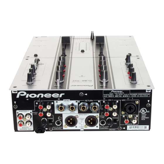
Page 11: Rear Panel
51 CH-1 PLAYER CONTROL jack cassette deck or other line signal level component. When a Pioneer DJ CD player is connected to the CH-1 CD jacks, a special control cord can be used to connect this jack 44 External effector output jacks (SEND) to the player’s control jack, thus enabling the fader start... -
Page 12: Fader Operations
Fader Start Function no functional effect takes place) at the two extreme ends of When the CH-1 and CH-2 jacks of this unit are connected to a the top panel cross fader lever movement can be adjusted by separately sold Pioneer DJ CD player (models CDJ-1000, using the front panel’s FADER CUT LAG dial, within a range... - Page 13 FEELING ADJ. ÷ If the cue point has already been set, there is no need to set the CD player again for standby at the cue point. ÷ If the cue point has already been set, there is no need to ÷...
-
Page 14: Troubleshooting
Sometimes the trouble may originate from another component. Thus, also check the other electrical appliances also in use. If the trouble cannot be rectified even after checking the following items, contact your dealer or nearest PIONEER service center. Problem... -
Page 15: Specifications
Power supply voltage ........AC 120 V, 60 Hz Power consumption ............23 W Output terminal (output level/impedance) Operating temperature ..+5 °C to +35 °C (41 °F to 95 °F) MASTER OUT 1 (XLR) ......0 dBV (1 V) / 600 Operating humidity ..........5% to 85% MASTER OUT 2 (RCA) ...... - Page 16 PIONEER CORPORATION 4-1, Meguro 1-Chome, Meguro-ku, Tokyo 153-8654, Japan PIONEER ELECTRONICS (USA) INC. Multimedia and Mass Storage Division: 2265 East 220th Street, Long Beach, CA 90810, U.S.A. TEL: 800-444-OPTI (6784) PIONEER ELECTRONICS OF CANADA, INC. Industrial Products Department: 300 Allstate Parkway, Markham, Ontario L3R OP2, Canada TEL: 905-479-4411 <TSZRW/03J00000>...