Advertisement
Quick Links
TM
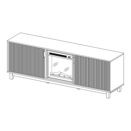
Arundo 70" Fireplace TV Stand
SKU# WEARU22704
For Residential Use Only
Please visit our website for the most current instructions, assembly tips, report damage,or request parts. www.walkeredison.com
2024 by Walker Edison Furniture Co., LLC. All rights reserved. Revised 18/06/2024 (F)
1
©
Copyright
Advertisement

Related Manuals for Walker Edison Arundo WEARU22704


Summary of Contents for Walker Edison Arundo WEARU22704
- Page 1 Arundo 70” Fireplace TV Stand SKU# WEARU22704 For Residential Use Only Please visit our website for the most current instructions, assembly tips, report damage,or request parts. www.walkeredison.com 2024 by Walker Edison Furniture Co., LLC. All rights reserved. Revised 18/06/2024 (F) © Copyright...
- Page 2 You can cause cracking or damage to the material and easily strip the hardware. If you choose to use a power tool, your product will no longer be covered under Walker Edison’ warranty. Glue is provided to secure wood dowels in place When inserting dowels, locate the appropriate hole, place a small amount of glue in the hole, and then insert the dowel.
-
Page 3: Parts List
Parts List Part Number Description Quantity Top Panel Bottom Panel Left Panel Right Panel Left Divider Panel Right Divider Panel Front Mullion Upper Rail Back Panel Adjustable Shelf Left Door Right Door Long Apron Short Apron Middle Foot... -
Page 4: Hardware List
Hardware List Part Size Name Quantity 8x30mm Wooden dowel 6x35mm Cam Bolt 15x11mm Cam Lock Plastic Wedge 3x17mm Screw 8x5x16mm Shelf support pin 6x50mm Bolt Hex key Handle 3x12mm Screw 35mm European hinge 3.5x14mm Screw 4x45mm Screw... - Page 5 Hardware List Part Size Name Quantity 4x32mm Screw 4x12mm Screw L-Shaped bracket RV18V80L-MT2 Flreplace lnsert 30mm Sticker Silicone pad Glue tube The hardware quantities listed above are required for proper assembly. Extra hardware pieces may be included.
- Page 6 Step 1 Let’s get started! Insert Dowels (A) into the Upper Rail (8), both Long Aprons (13), and both Short Aprons (14). 1: The provided glue is to secure wood dowels in place. When first inserting dowels, locate the appropriate hole for the dowel, place a small amount of glue in the hole and insert the dowel.
- Page 7 Step 2 Next, insert Dowels (A) into the Left Panel (3), Left Divider Panel (5), Right Divider Panel (6) and the Right Panel (4).
- Page 8 Step 3 Using a screwdriver, attach the Cam Bolts (B) to the Top Panel (1), both Front Mullions (7), and all four Legs (15).
- Page 9 Step 4 Insert one Front Mullion (7) into the Left Divider Panel (5) and the other Front Mullion (7) into the Right Divider Panel (6). Secure with Cam Locks (C) and tighten with a screwdriver. Cam Locks Cam Locks help securely join two pieces together. Follow these easy steps.
- Page 10 Step 5 Insert the Legs (15) into both ends of the Short Apron (14). Secure with Cam Locks (C) and tighten with a screwdriver. Repeat this step on the second Short Apron (14).
- Page 11 Step 6 Now, insert the Legs (15) into both Long Aprons (13) to complete the bottom frame. Secure with Cam Locks (C) and tighten with a screwdriver.
- Page 12 Step 7 Next, insert Dowels (A) into the Long Aprons (13) and the Short Aprons (14).
- Page 13 Step 8 Secure each Middle Foot (16) to the Bottom Panel (2) using the 50 mm Bolt (G). Tighten the connection with the Hex key (H).
- Page 14 Step 9 Attach the Left Divider Panel (5) and the Right Divider Panel (6) to the Bottom Panel (2) using the 50 mm Bolt (G). Tighten the connection with the Hex key (H).
- Page 15 Step 10 Using a screwdriver, secure the bottom frame made with Long Aprons (13) and Short Aprons (14) to the Bottom Panel (2) using the 45 mm Screw (N).
- Page 16 Step 11 Use the 50 mm Bolt (G) to further secure the Legs (15) to the Bottom Panel (2). Tighten the connection with the Hex key (H).
- Page 17 Step 12 Next, attach the Left Panel (3) and the Right Panel (4) to the Bottom Panel (2) using the 50 mm Bolt (G). Ensure a solid connection by tightening with the Hex key (H).
- Page 18 Step 13 Secure the Upper Rail (8) to the Top Panel (1) using the 32 mm Screws (P).
- Page 19 Step 14 Have a friend help you flip the unit so that the Legs (15) are on the floor. Slide the Back Panels (9) into place using the grooves.
- Page 20 Step 15 Insert the Top Panel (1) into the Left Panel (3), Left Divider Panel (5), Right Divider Panel (6), and the Right Panel (4). Secure with Cam Locks (C) and tighten with a screwdriver.
- Page 21 Step 16 Place Stickers (T) over each interior Cam Lock (C) to ensure a clean finish.
- Page 22 Step 17 Insert the Shelf support pins (F) into the Left Panel (3), Left Divider Panel (5), Right Divider Panel (6), and the Right Panel (4). Then, with the finished edge facing out, slide the Adjustable Shelves (10) into place. Make sure the notches on the shelves fit onto the Shelf support pins (F).
- Page 23 Step 18 Now, attach the Handles (J) to the Left Door (11) & Right Door (12) using the 12 mm Screws (K). On the same side as the Handles (J), secure the Silicone pads (U) to both corners. Then, attach the Hinges (L) to each door using the 3.5x14 mm Screws (M).
- Page 24 Step 19 Using a screwdriver, attach the Left Door (11) to the Left Panel (3) using the 14 mm Screws (M). Adjusting The Cabinet Doors Adjust horizontal width Adjust depth position Adjust vertical height with this screw. by loosening the hinge arm via the screws in the mounting screw.
- Page 25 Step 20 Now, let’s attach the Right Door (12) to the Right Panel (4) using the 14 mm Screws (M).
- Page 26 Step 21 Evenly space the Plastic Wedges (D) between the Back Panels (9) and the frame. Secure the wedges into place using the 17 mm Screws (E).
- Page 27 Step 22 Use the adjustable Feet (16) to ensure a level surface.
- Page 28 Step 23 Insert the Fireplace Insert (S) into place on the back side of the tv stand.
- Page 29 Step 24 Attach the Fireplace Insert (S) to the tv stand by attaching the L-Shaped Bracket (R) to the Right Divider Panel (6) using 12mm Screws (Q).
- Page 30 Step 25 Repeat for the other side. Attach the other L-Shaped Bracket (R) to the Left Divider Panel (5) using 12mm Screws (Q).
- Page 31 Step 26 For your safety, please ensure that your Fireplace is securely plugged into the wall outlet, and that it is the only device connected to the outlet.
-
Page 32: Final Assembly
Final Assembly Congratulations, you did it! Cozy up and enjoy your new fireplace tv stand! Congratulations on your new piece of furniture! We would love to hear about it and see it. Please leave us a review or post a picture with #mywalkeredisonhome... - Page 33 Assembling furniture can be tricky sometimes. Our customer service team, located in Utah, is here for product information, help assembling a product, or for any other customer support issue Call us at 801-433-3008 Email us at service@walkeredison.com Visit our Customer Service website at walkeredison.com/pages/customer-service We are available to help Monday -Thursday 8am-5pm, Friday 8am-3pm MST...
Need help?
Do you have a question about the Arundo WEARU22704 and is the answer not in the manual?
Questions and answers