Table of Contents
Advertisement
Quick Links
This manual provides information regarding
the operation and maintenance of these
products. We have made every effort to
ensure the accuracy of the information in
this manual. We reserve the right to change
this product at any time without prior
notice.
XP7000IH
U
S
E
R
Call our Customer Care Team Toll Free 8-5 PM PST Mon-Fri
844-DUROMAX
M
A
N
U A
5800 Ontario Mills Pkwy
Ontario, CA 91764 USA
www.duromaxpower.com
L
Advertisement
Table of Contents
Troubleshooting

Related Manuals for DUROMAX XP7000IH


Summary of Contents for DUROMAX XP7000IH
- Page 1 XP7000IH This manual provides information regarding the operation and maintenance of these products. We have made every effort to ensure the accuracy of the information in this manual. We reserve the right to change 5800 Ontario Mills Pkwy this product at any time without prior Ontario, CA 91764 USA notice.
-
Page 3: Table Of Contents
CONTENTS Introduction Introduction ........................6 General Safety Procedures ................... 8 Carbon Monoxide Safety ..................... 12 Unit and Purchase Information .................. 14 Generator Components Generator Components ....................16 Package Contents ......................18 Generator Setup Connect the Battery ..................... 20 Adding Oil ........................21 Adding Gasoline ...................... - Page 4 CONTENTS Stopping the Generator Shutting Down the Generator On Gasoline ..............52 Shutting Down the Generator On Propane ..............53 Shutting Down the Generator With the Remote ............54 Maintenance and Care Maintenance Schedule ....................56 Break-In Period ......................57 Maintenance Log ......................
- Page 6 DUROMAX The DuroMax Way is more than just a brand, it is our understanding and appreciation of just how important power can be to someone without it… DUROMAX FOR HOME DUROMAX FOR WORK DUROMAX FOR PLAY Electricity in our home not...
-
Page 7: Introduction
INTRODUCTION DuroMax Power Equipment is headquartered in Ontario, California and is the industry’s leader in Dual Fuel portable generator technology. In addition to a full assortment of portable generators ranging from digital inverters to large 15,000-watt portable standby units, their product line includes pressure washers, engines, pumps, and accessories. -
Page 8: General Safety Procedures
GENERAL SAFETY PROCEDURES SAFETY ALERT SYMBOL The safety alert symbol is used with one of the safety words (DANGER, WARNING, or CAUTION) to alert you of hazards. Please pay attention to these hazard notices both in this manual and on the engine. Please familiarize yourself with the following safety symbols and words: ●... - Page 9 WARNING: This generator may emit highly flammable and explosive gasoline vapors, which can cause severe burns or even death. A nearby open flame can lead to an explosion even if not directly in contact with gasoline. ● Do not operate near an open flame. ●...
- Page 10 GENERAL SAFETY PROCEDURES (CONTINUED) Button/Coin Battery Warnings AWARNING MODEL: 3V CR2032 INGESTION HAZARD This product contain a button cell or coin battery This symbol means: INGESTION HAZARD: ;3 This product contains a button cell or coin battery. 1. Remove and immediately recycle or dispose of used batteries according to local regulations and keep away from children.
- Page 11 In addition to the above safety notices, please familiarize yourself with the safety and hazard markings on the generator.
-
Page 12: Carbon Monoxide Safety
“the silent killer.” CO ALERT Description The DuroMax CO ALERT system was created to protect our customers and their families from dangerous carbon monoxide. Just like the detector for your home the CO ALERT tests the air for to keep you safe and healthy. - Page 13 As the only safe way to use a portable generator, taking your generator outside is absolutely mandatory to keep your family safe from carbon monoxide. But there’s even more you can do. By educating yourself about all carbon monoxide risks, you’ll be better prepared to protect your family from this colorless, odorless threat.
-
Page 14: Unit And Purchase Information
UNIT AND PURCHASE INFORMATION Serial Number Serial number The serial number is located on the back of the generator and next to the wheel. Serial number format The serial number will be shown in two parts. The engine model, followed by the serial number. Engine Model: _____________________________________________ Serial Number: _____________________________________________ STAPLE RECEIPT HERE... - Page 15 GENERATOR COMPONENTS To help you get familiar with your new DuroMax generator, please see this component section for easy reference on all the generator’s individual features.
-
Page 16: Generator Components
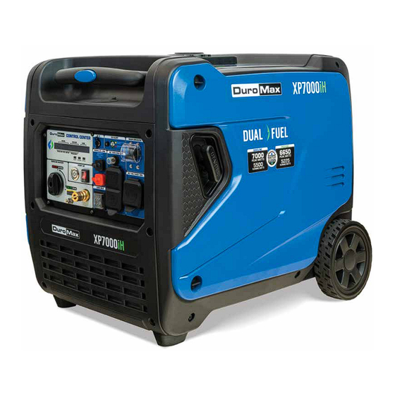
GENERATOR COMPONENTS 3. Fuel Tank 2. Handles 4. Right Service 1. Power Panel Panel 5. Wheels 1. Power Panel - Contains the start switch, plugs, meters, and circuit breakers. 2. Handles - Allow for easy steering during transportation. 3. Fuel Tank - A 3 gallon gasoline fuel tank. 4. - Page 17 10. Battery Tender 11. CO Alert 9. Start Up Switch 8. Start Button 12. Parallel Ports 7. Multimeter 13. Main Circuit Breaker 6. Fuel Valve 17. 240V 30A Receptacle 14. LPG Inlet 16.120V GFCI Receptacles 15. Low Idle 10. Battery Tender - Easily keep your battery charge when the generator is in storage by using the included battery tender.
-
Page 18: Package Contents
PACKAGE CONTENTS Your generator comes with the items listed below. Please check to see that all of the following items are included with your generator. Battery Tender Oil Funnel w/ Hose Spark Plug Wrench Used to add oil to the Used to charge the battery Used in spark plug generator without messy spills. -
Page 19: Generator Setup
GENERATOR SETUP Proper setup of your generator will get you going as soon as possible while making sure you and your equipment are safe and cared for. -
Page 20: Connect The Battery
GENERATOR SETUP (CONTINUED) Step 1 - Connect the Battery Remove maintenance cover Remove the left maintenance cover by removing both thumbscrews and removing the cover. Locate the battery cables Locate the battery cables above and behind the battery. One side is connected to the housing and the other end is attached to the battery terminals. -
Page 21: Adding Oil
. You must add the proper amount of oil before operating the generator for the first time. This amount is equal to the oil capacity of the engine crankcase: Model Number XP7000iH Engine Oil Capacity 23.7 fl. oz. (0.7 L) WARNING: Do not apply engine oils with additives or 2-stroke gasoline engine oils;... -
Page 22: Adding Gasoline
Replace fuel cap and wipe up any spilled gasoline with a dry cloth. Model Number XP7000iH Gas Tank Capacity 3 US Gal. (11.4 L) DANGER DO NOT OVERFILL 1.5”... -
Page 23: Grounding The Generator
Step 4 - Grounding the Generator Attach grounding wire Ground the generator by tightening the grounding nut against a grounding wire. Connect the other end to a copper or brass grounding rod that’s driven into the earth. A generally acceptable grounding wire is a No. 12 AWG (American Wire Gauge) stranded copper wire. -
Page 25: Starting The Generator
STARTING THE GENERATOR If this is not your first time using the generator there are still steps you should take to prepare it for operation each time you use it. IMPORTANT: At this point, you should be familiar with the procedures described in the first portion of this section entitled “GENERATOR SETUP”... -
Page 26: Check The Oil
(see “Adding Oil” portion of the “Maintenance” section). Be sure to replace the cap when finished checking oil. Model Number XP7000iH Engine Oil Capacity 23.7 fl. oz. (0.7 L) -
Page 27: Check The Gas Level
Step 2 - Check the Gas Level (Optional) Check fuel level If running the engine on gasoline, check to see that there is sufficient gasoline in the fuel tank. The fuel gauge on the control center display will give a rough estimate of the gasoline level. -
Page 28: Starting The Generator Using Gasoline
STARTING THE GENERATOR Starting the Generator Using Gasoline Turn start switch ON The start switch is located on the top center of the front power panel next to the START button. Press the switch up to the ON position to allow the generator to start. Turn gas valve ON The gas valve is located the left hand side of the panel. - Page 29 Press the START button The START button is located on the top center of the power panel. Press the button down for 1-3 seconds to start the generator. Turn main breaker ON/Connect The breaker is located in the top right of the front power panel.
-
Page 30: Starting The Generator Using Propane
STARTING THE GENERATOR (CONTINUED) Starting the Generator Using Propane Connect propane hose The LPG inlet is located on the bottom left of the front panel. Connect the propane hose to both the inlet and the propane tank. Open the propane tank. Turn gas valve ON The gas valve is located the left hand side of the panel. - Page 31 Turn start switch ON The start switch is located on the top center of the front power panel next to the START button. Press the switch up to the ON position to allow the generator to start. Press the START button The START button is located on the top center of the power panel.
- Page 32 STARTING THE GENERATOR (CONTINUED) Starting the Generator Using Propane WARNING: WHEN USING THE GENERATOR WITH LPG, MAKE SURE THERE IS NO POSSIBLE IGNITION SOURCE CLOSE TO THE GENERATOR. 1. Before using, make sure all of the LPG connectors and hoses are well connected and sealed.
-
Page 34: Starting The Generator Using Recoil Start
STARTING THE GENERATOR (CONTINUED) Starting the Generator Using Recoil Start Select fuel Follow step 2 on “Starting the Generator Using Gasoline” section if your using gasoline, or steps 1 and 2 on “Starting the Generator Using Propane” section if your using propane. Shut main breaker OFF The breaker is located on the top right of the front power panel. - Page 35 Pull the recoil start The recoil start is located on the right side of the generator. Pull the recoil handle slowly until resistance is felt, then quickly pull the recoil handle until fully extended. CAUTION: Release the recoil handle only after the cord has retracted.
-
Page 36: Starting The Generator Using Remote Start
STARTING THE GENERATOR (CONTINUED) Starting the Generator Using Remote Start Select fuel Follow step 2 on “Starting the Generator Using Gasoline” section if your using gasoline, or steps 1 and 2 on “Starting the Generator Using Propane” section if your using propane. Turn main breaker ON The breaker is located in the top right of the front power panel. - Page 37 Push the START button The remote start has two buttons, START and STOP. Press the START button two times in succession to start the generator.
-
Page 39: Using The Generator
USING THE GENERATOR If this is not your first time using the generator, there are still steps you should take to prepare it for operation each time you use it. IMPORTANT: At this point, you should be familiar with the procedures described in the first portion of this section entitled “GENERATOR SETUP”;... -
Page 40: Ac Usage
USING THE GENERATOR AC Usage ● You may connect electrical devices running on AC current according to their wattage requirements. ● The chart below shows the rated and surge wattage of your generator according to its model number. ● The rated wattage corresponds to the maximum wattage the generator can output on a continuous basis. - Page 41 Tool or Appliance Rated (Running) Watts Additional Surge Watts Electric water heater (40 gal) 4000 Hot plate 2500 Radial arm saw 2000 2000 Electric stove 1500 Circular saw 1500 1500 Air compressor (1 HP) 1500 3000 Window air conditioner 1200 1800 Miter saw 1200...
-
Page 43: Connecting The Generator To A Home
USING THE GENERATOR (CONTINUED) Connecting the Generator to a Home Interlock kit ● Choose what circuits you want to run. ● Requires an electrician to install, but you have the flexibility of switching up your circuits depending on your power needs. ●... -
Page 44: Connecting A Load To The Generator
USING THE GENERATOR (CONTINUED) Connecting a Load to the Generator NOTE: Be sure to attach devices to the correct receptacle (outlet). 120V devices can be directly connected to the 120V ONLY receptacles. ● ● 120V devices can be connected to the 120/240V receptacle using an appropriate adapter. ●... -
Page 45: Choosing The Right Power Cord
*Gauge based on twisted copper wire From home back up to just running your electric edger and everything in-between DuroMax has the power cord for you. All DuroMax cords are 100% twisted copper wire for maximum life and reliability. 120V 15A... -
Page 46: Using The Digital Multimeter
USING THE GENERATOR (CONTINUED) Using the Digital Multimeter 1. Runtime/Total Hours 2. Voltage 3. Load 5. Frequency 4. Gasoline Fuel Meter 1. Runtime/Total Hours – This portion of the display will automatically switch between the current runtime and total runtime hours of the unit. 2. -
Page 47: Low Idle Usage
Low Idle Usage Low Idle The low idle feature automatically lowers the RPM of the generator based on the current load to help conserve fuel and lower the noise of the generator. Turn on the low idle for better fuel efficiency and to make the generator quieter. -
Page 49: Using The Battery Tender
USING THE GENERATOR (CONTINUED) Using the Battery Tender The generator battery can steadily lose charge during longer periods of storage. Plug the provided trickle charger in to ensure your battery is maintained and ready for use if needed. CAUTION: Avoid allowing the 12V battery to drop below 11.6V of charge, this can cause permanent damage to the battery cells. -
Page 51: Stopping The Generator
STOPPING THE GENERATOR This section will cover the recommended shut off procedure for stopping the generator on various fuels. -
Page 52: Shutting Down The Generator On Gasoline
STOPPING THE GENERATOR Shutting Down the Generator On Gasoline Flip the main breaker OFF The breaker is located on the top right of the front power panel. Flip the breaker down to the OFF position. Run the generator Allow the generator to run for 3-5 minutes. Turn the generator OFF Hold the start button for 3 seconds to shut off the generator. -
Page 53: Shutting Down The Generator On Propane
Shutting Down the Generator On Propane Turn OFF the main breaker Move the main breaker to the OFF position. Run the generator Allow the generator to run for 3-5 minutes. Turn start switch OFF Turn the start switch to the OFF position. Close the propane tank valve Turn your propane tank valve to the CLOSE position. -
Page 54: Shutting Down The Generator With The Remote
STOPPING THE GENERATOR (CONTINUED) Shutting Down the Generator With the Remote Flip the main breaker OFF The breaker is located on the top right of the front power panel. Flip the breaker down to the OFF position. Run the generator Allow the generator to run for 3-5 minutes. -
Page 55: Maintenance And Care
MAINTENANCE AND CARE Proper maintenance and storage of your generator are essential to ensure trouble-free use of your generator when you need it. By following the maintenance and care requirements, you can keep your generator running smoothly and efficiently for years to come. -
Page 56: Maintenance Schedule
MAINTENANCE AND CARE Proper routine maintenance of your generator is essential for safe, economical, and trouble-free operation. It will also help reduce air pollution. WARNING: Improper maintenance, or failure to correct a problem before operation, can cause a malfunction in which you can be seriously injured or killed. Always follow the inspection, maintenance recommendations, and schedules in this instruction manual. -
Page 57: Break-In Period
Break-In Period As the best practice for any new combustion motor it’s recommended to perform the break in procedure as follows: ● Run the generator for the first 6-8 hours on conventional oil, then change the oil. After the break-in period synthetic oil may be used. ●... -
Page 59: Checking The Oil
(see “Adding Oil” portion of the “Maintenance” section). The oil will be visible in the oil fill spout when full. Be sure to replace the cap when finished checking oil. Model Number XP7000iH Engine Oil Capacity 23.7 fl. oz. (0.7 L) -
Page 60: Changing The Oil
MAINTENANCE AND CARE (CONTINUED) Changing the Oil CAUTION: Worn out or dirty oil does not cool the generator properly and can lead to catastrophic engine damage. In addition to regular oil changes, it is necessary to drain the oil from the crankcase if it has become contaminated with water or dirt. - Page 61 Replace cap Replace the oil drain cap. Add new oil Remove oil fill cap and add new oil to engine. Replace maintenance cover Replace maintenance cover and tighten both thumbscrews to secure the cover.
-
Page 62: Cleaning The Air Filter
MAINTENANCE AND CARE (CONTINUED) Cleaning the Air Filter Routine maintenance of the air cleaner helps maintain proper airflow to the carburetor. Check that the air cleaner is free of excessive dirt after every use. CAUTION: Improper maintenance may cause less air to enter the engine or dirty air to enter the engine causing overheating and engine wear. - Page 63 Wash cleaner element Wash the sponge-like elements in household dish detergent and warm water. Dry cleaner element Pat dry on a dry cloth and allow the elements to dry completely. Add engine oil to elements Soak the dry elements in a small amount of engine oil. Ring out any excess oil.
-
Page 64: Spark Plug Maintenance
MAINTENANCE AND CARE (CONTINUED) Spark Plug Maintenance The spark plug is important for proper engine operation. SPARK PLUG A good spark plug should be intact, free of deposits, and CONSULT MANUAL properly gapped. BEFORE REMOVING CAUTION: Improper maintenance may cause reduced fuel economy, misfires, trouble starting, or damage to the spark plug threads. - Page 65 Remove spark plug Unscrew the spark plug from the generator using the spark plug wrench included with this product. Inspect spark plug and gap Visually inspect the spark plug. If it is cracked or chipped, discard and replace it with a new spark plug. We recommend using an NGK BPR6ES spark plug.
-
Page 66: Emptying The Gas Tank
MAINTENANCE AND CARE (CONTINUED) Emptying the Gas Tank If you have been using gasoline in your generator, before storing your generator for extended periods of time you should drain your generator fuel tank of gasoline. CAUTION: Do not store fuel from one season to another. - Page 67 Turn fuel valve ON Turn the fuel valve clockwise to the FUEL ON position and allow the gas to fully drain from the gas tank. Once the fuel is fully drained turn the fuel valve counter-clockwise to the FUEL OFF position.
-
Page 68: Transporting The Generator
MAINTENANCE AND CARE (CONTINUED) Transporting the Generator Empty the gas tank Fully drain your gas tank as shown in “Emptying the Gas Tank” on page 66-67. Disconnect the spark plug Pull on spark plug cap to disconnect spark plug from ignition wire as shown in “Spark Plug Maintenance”... -
Page 69: Storing The Generator For Use Within 30 Days
Storing the Generator for Use Within 30 Days Add fuel stabilizer to gas tank Add fuel stabilizer to gas tank to help preserve gasoline for longer storage period. Flip main breaker OFF and run Turn OFF the main breaker and allow the generator to run for 3-5 minutes. -
Page 70: Storing The Generator For Longer Than 30 Days
MAINTENANCE AND CARE (CONTINUED) Storing the Generator for Longer Than 30 Days Add fuel stabilizer to gas tank Add fuel stabilizer to gas tank to help preserve gasoline for longer storage period. Flip main breaker OFF and run Turn OFF the main breaker and allow the generator to run for 3-5 minutes. - Page 71 Remove spark plug Remove spark plug as shown in “Spark Plug Maintenance” on page 64. Add oil to cylinder Add 2 tablespoons of 10W-30 motor oil directly into the spark plug hole on each side, and pull the recoil to lubricate cylinder.
-
Page 72: Specifications
SPECIFICATIONS Model Number XP7000iH AC Rated Wattage (Gasoline) 5,500 W AC Rated Wattage (Propane) 5,225 W AC Surge Wattage (Gasoline) 7,000 W AC Surge Wattage (Propane) 6,650 W AC Rated Voltage 120/240V Dimensions 25.1” L x 19.4” W x 21.38” H... -
Page 73: Troubleshooting
TROUBLESHOOTING This section of the manual is to help you troubleshoot problems with your generator. -
Page 74: Basic Troubleshooting
TROUBLESHOOTING Mode Description Solution Battery not charged Charge battery Engine switch is in the “OFF” Turn engine switch to the “ON” position position Stale gasoline or water in gaso- Drain entire system and refill line with fresh fuel Engine is out of fuel Add fuel Engine will not start Fuel is old or contaminated... -
Page 76: Warranty
OEM parts. Warranty Limitations DuroMax Power Equipment does not claim or hold any obligation to loss of time, freight charges, use of the product, or any incidental damages from the use of this product. THIS WARRANTY IS IN LIEU OF ALL OTHER WARRANTIES, EXPRESSED OR IMPLIED. - Page 77 The California Air Resources Board, The United States Environmental Protection Agency (US EPA) and DuroMax Power Equipment, are pleased to explain the emission control system warranty on your 2023-2024 year small off-road engine. In the United States and California, new small off-road engines must be designed built and equipped to meet the State’s stringent anti-smog standards.
- Page 78 If the part fails prior to the first scheduled replacement, the part must be repaired or replaced by DuroMax Power Equipment according to Subsection (4) below. Any such part repaired or replaced under warranty must be warranted for the remainder of the period prior to the first scheduled replacement point for the part.
- Page 79 (7) DuroMax Power Equipment is liable for damages to other engine components proximately caused by a failure under warranty of any warranted part.
- Page 80 (i) Electronic controls (ii) Vacuum, temperature, and time- sensitive valves and switches. (iii) Hoses, belts, connectors, and assemblies. DuroMax Power Equipment will furnish with each new engine written instructions for the maintenance and use of the engine by the owner...
-
Page 81: Contact Information
CUSTOMER SERVICE DEPARTMENT DuroMax Power Equipment is committed to ensuring that our products perform when they need to. Our generators are your lifeline in the event of an emergency. Should you have any problems, please contact our customer service department:... - Page 82 5800 Ontario Mills Parkway Ontario, CA 91764 United States 844-DuroMax REV: XP7000iH-02162024...
Need help?
Do you have a question about the XP7000IH and is the answer not in the manual?
Questions and answers