Table of Contents
Advertisement
Advertisement
Table of Contents

Related Manuals for Linde 115 Series


Summary of Contents for Linde 115 Series
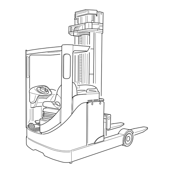
- Page 1 R 16 R 16 HD R 16 N R 20 R 20 N Series 115 115-02 This document is only provided for your use during training and it remains the exclusive property of LINDE MATERIAL HANDLING (UK) LTD Kingsclere Rd. Basingstoke...
-
Page 3: Table Of Contents
Table of Content Service Training 09.06 Page ELECTRIC REACH TRUCK R 14, R 14 HD, R 16, R 16 HD, R 16 N, R 20, R 20 N SERIES Traction motor and brake Traction motor 1.1.2 Traction motor removal 1.1.2.1 Traction motor refitting 1.1.3 Traction motor dismantling... - Page 4 Table of Content Service Training 09.06 Page Seat 3.2.1 Seat adjustment 3.2.2 Seat removal Floorplate removal 3.3.1 Floorplate refitting Battery carrier 3.4.1 Battery carrier removal 3.4.2 Battery carrier lubrication 3.3.3 Battery carrier replacement Battery changing (hoist method) 02.01 Battery changing (roll on, roll off) 09.03 Covers and panelling 09.03...
- Page 5 Table of Content Service Training 09.06 Page Brake bleeding Load wheel brakes 5.4.1 Load wheel brake cylinders 5.4.2 Load wheel brake cylinder maintenance 5.4.3 Load wheel brake cylinder repair instructions Load wheel brake shoes 5.5.1 Load wheel brake shoes maintenance and inspection 5.5.2 Load wheel brake shoe removal 5.5.3...
- Page 6 Table of Content Service Training 09.06 Page 6.1.5.5 Freewheel circuit 6.1.5.6 Regenerative electrical braking (useful current braking) 6.1.5.7 Electrical braking - Selecting opposite direction of travel. 6.1.6 Control circuit 6.1.6.1 1X11, 29 way connector 6.1.6.2 1X12, 29 way connector 6.1.7 Program memory replacement 6.1.8 Emergency off microswitch...
- Page 7 Table of Content Service Training 09.06 Page 6.2.8 Hydraulic enable signal 6.2.8.1 Hydraulic release signal 6.2.9 Hydraulic power supply 6.2.10 Hydraulic control circuit 6.2.10.1 LLC Voltage supply 6.2.11 Joysticks 6.2.11.1 Single axis lever bracket and connector positions 6.2.11.2 Dual axis lever bracket and connector positions 6.2.11.3 Joystick 6.2.12...
- Page 8 Table of Content Service Training 09.06 Page 6.4.3.1 Hour meters 09.03 6.4.4 Help prompts 09.03 6.4.5 Fan control 09.03 Diagnostic concept 09.03 6.5.1 Help files 09.03 6.5.2 Truck Onboard Diagnostics (TOD) 09.03 6.5.3 LDC diagnostic windows 03.04 6.5.3.1 LDC fault codes 03.04 6.5.4 LLC Diagnostic windows...
- Page 9 Table of Content Service Training 09.06 Page Reach cylinder re-fitting 7.9.1 Reach cylinder 7.9.2 Reach cylinder dismantling 7.9.3 Reach cylinder reassembly 7.10 Tilt and lift cylinder hoses Mast unit and attachments Introduction Forks removal 8.2.1 Forks refitting 8.2.2 Forks inspection 8.2.3 Fork latches Mast unit removal...
- Page 10 Table of Content Service Training 09.06 Page 8.14.2 Tilting sideshift unit refitting (187 mast) 09.03 8.14.3 Tilting sideshift unit dismantling 187 mast 09.03 8.14.4 Tilting sideshift reassembly 187 mast 09.03 8.15 Tilting sideshift assembly (184 mast) 09.03 8.15.1 Tilting sideshift unit removal (184 mast) 09.03 8.15.2 Tilting sideshift unit-replacement (184 mast)
- Page 11 Table of Content Service Training 09.06 Page 9.1.5 Cabin interior lights 9.1.6 Cabin exterior lighting 9.1.7 Cabin loudspeakers and microphone 9.1.8 Cabin control module 4A1 9.1.8.1 Cabin control module pin duties 9.1.9 Cabin fuses 9.1.9.1 Cabin fuse duties and positions Height preselection (LPS) and lift height indicator (LHI) 9.2.1 LPS System overview...
- Page 12 Table of Content Service Training 09.06 Page...
- Page 13 CAUTION: If the battery has been disconnected, before reconnecting, ensure that the emergency isolator is depressed and the keyswitch is turned off. DO NOT FIT PARTS OTHER THAN THOSE AVAILABLE FROM LINDE MATERIAL HANDLING (UK) LIMITED, OR ALTER EXISTING EQUIPMENT. INCORPORATION OF PARTS OTHER THAN THOSE SUPPLIED BY LINDE MATERIAL HANDLING (UK) LIMITED OR ALTERATION OF EXISTING EQUIPMENT WITHOUT THE MANUFACTURER’S PERMISSION MAY MAKE THE...
- Page 14 Inroduction Service Training 09.03 Page ELECTRICAL SAFETY CHECKS Should major electrical work or disassembly be carried out on the truck, then the following electrical safety checks MUST be carried out prior to returning the truck into service. - Depress the emergency isolator, and disconnect the battery. - Connect a FUSED shorting link between traction LTM studs 1A1:1 and 1A1:2.
- Page 15 Inroduction Service Training 03.04 Page SAFETY The warning precautions DANGER, WARNING, CAUTION and NOTE in this manual are provided to indicate special dangers or unusual information requiring special identification: DANGER: Indicates hazards that may result in bodily injury or death and/or severe product damage.
- Page 16 Inroduction Service Training 03.04 Page WARNING: Before disconnecting hydraulic connections, ensure that there is no pressure in the system. WARNING: Do not allow hydraulic oil under pressure, for example at a leak, to penetrate the skin. Medical aid is required if such an injury occurs. DANGER: Never wear rings, wrist watches, jewellery, loose or dangling items of clothing such as ties, torn clothing, scarves, unbuttoned jackets or overalls with open zip fasteners that could get caught up in moving parts.
-
Page 17: Traction Motor And Brake
The motor also incorporates a transmission brake mounted directly to the armature shaft, which is operated by either the foot brake or a solenoid brake within the same unit. Motor temperature and brush condition are monitored, with warnings for these shown on the Linde Intelligent Display (LID). - Page 18 Section Service Training Page - At the connector bracket, disconnect 1X19 (Brake solenoid) and 1X7 (Temperature and Brushwear). - Remove the connector bracket. NOTE: This is secured by two of the steer motor securing bolts. - Remove connectors 1X19 and 1X7 from the bracket and secure the harnesses to the motor to prevent damage.
-
Page 19: Traction Motor Refitting
Section Service Training Page - Using suitable lifting equipment, remove the motor. 115_01-27 1.1.2.1 TRACTION MOTOR REFITTING - To replace the traction motor, reverse the removal procedure, ensuring all fasteners are tightened to the correct torque. - Check steer sensors for correct adjustment. - Bleed the brakes, see SECTION 5. - Page 20 Section Service Training Page THE TRACTION MOTOR 1. Bush 16. Brush 31. Spring washer 2. Bearing 17. Hexagon screw 32. Socket head screw 3. Retaining ring 18. Raised head screw 33. Spring washer 4. O ring 19. Wave washer 34. Socket head screw 5.
-
Page 21: Traction Motor Dismantling
Section Service Training Page 1.1.3 TRACTION MOTOR DISMANTLING - Remove brush cover (43). - Disconnect and remove brushes (16) from the brush holder in the brush holder assembly (15). NOTE: Ensure the brushes are marked, and returned to their original position on re- assembly. -
Page 22: Traction Motor Commutator Refacing
Section Service Training 02.01 Page 1.1.6 TRACTION MOTOR COMMUTATOR REFACING The commutator may be refaced in a lathe with 00 or fine glass paper for superficial scores or pitting. Excessive pitting, scores or wear will require turning. Only light cuts of 0.13 mm and the final skim of 0.005 mm. -
Page 23: Traction Motor - Bedding The Brushes
Section Service Training 02.01 Page 1.1.8 TRACTION MOTOR - BEDDING THE BRUSHES When fitting new brushes the brushes should be bedded to the commutator. New brushes should first be bedded to the commutator using fine sand paper to obtain a rough shape. A commutator stone may be used for final bedding. -
Page 24: Parking Brake Adjustment
Section Service Training Page PARKING BRAKE ADJUSTMENT WARNING: The traction motor can become very hot. Risk of scalding. By using Window 61 of the LDC diagnostics, the calculated gap between the friction plates and brake drum when the brake is released, can be ascertained. This gap should be between 0.3 mm and 0.6 mm (0.45 optimum) In order to adjust the parking brake, special tool No. - Page 25 Section Service Training Page - Place the washer over the inner part of the tool. - Screw the outer part of the tool onto the inner part, so that the hexagon section is in contact with the washer. 115_01-5 - Turn the keyswitch on, and access window 61 of the traction diagnostics.
-
Page 26: Parking Brake Drum Removal
Section Service Training Page PARKING BRAKE DRUM REMOVAL WARNING: The traction motor can become very hot. Risk of scalding. The brake drum will need to be removed, should the friction plate need replacing. - Turn the keyswitch off. - Securely chock the drive wheel front and rear to prevent the traction motor armature from rotating. -
Page 27: Parking Brake Friction Plate Seal Renewal
Section Service Training Page PARKING BRAKE FRICTION PLATE SEAL RENEWAL When replacing the friction plate, new seals should be fitted. Replace the inner seal. 115_01-14 Replace the outer seal. 115_01-15... -
Page 28: Parking Brake Drum Replacement
Section Service Training Page PARKING BRAKE DRUM REPLACEMENT - Turn the keyswitch off. - Securely chock the drive wheel front and rear to prevent the traction motor armature from rotating. - Slacken the footbrake shoes. NOTE: Although not necessary, removing the footbrake shoes will facilitate brake drum replace- ment. - Page 29 Section Service Training Page - Replace the brake drum, allowing it to rest on the armature shaft. 115_01-19 - Screw the inner part of the tool fully into the armature shaft. CAUTION: Do not overtighten. 115_01-20 - Place the washer over the inner part of the tool. - Screw the outer part of the tool onto the inner part, so that the hexagon section is in contact with the washer.
- Page 30 Section Service Training Page - Using a 32 mm spanner, draw the drum onto the armature shaft until it is almost in contact with the friction pads. NOTE: The friction plate can be seen through the slotted holes in the drum. - Continue to draw the drum slowly onto the shaft, con- tinually checking that the drum is free to rotate.
-
Page 31: Traction Motor Cooling System
Section Service Training Page TRACTION MOTOR COOLING SYSTEM The traction motor is equipped with a cooling fan assembly, which forces air through a cooling duct into the motor when cooling is required, this is activated when the motor reaches 40°C 115_01-31 1. - Page 32 Section Service Training Page...
-
Page 33: Transmission
Section Service Training 09.06 Page TRANSMISSION DRIVE WHEEL REMOVAL - Apply the parking brake. - Raise the truck at the drive end approximately 300 mm using a suitable jack (1) and chock in position. - Turn the steering wheel full lock. - Remove accessible wheel nuts. -
Page 34: Gearbox Removal
Section Service Training Page 09.06 GEARBOX REMOVAL NOTE: If the gearbox is to be stripped down, it is advisable to remove the drive wheel first, see DRIVE WHEEL REMOVAL. - Remove the traction motor, see SECTION 1. - Remove the Steer motor, see SECTION 4. - Place a suitable tray beneath the gearbox, remove the gearbox drain plug and drain the gearbox oil. -
Page 35: Gearbox Refitting
Section Service Training 09.03 Page - Remove the four screws securing the gearbox. 115_02-05 - Using suitable lifting equipment, raise the front of the truck sufficiently to clear the gearbox and chock in position. - The gearbox can now be manoeuvred clear of the chassis. -
Page 36: Gearbox
Section Service Training Page GEARBOX 115_02-07 33. Socket head screw 1. Housing 17. Shim 34. Socket head screw 2. Cover 18. Bearing 35. Hexagon screw 3. Cover 19. Tapered roller bearing 36. Spring washer 4. Wheel shaft 20. Tapered roller bearing 37. -
Page 37: Steer Bearing Removal
Section Service Training 02.01 Page 2.3.1 STEER BEARING REMOVAL - Support the gearbox securely in an upright position. - Remove the 12 off screws (2) securing the bearing to the gearbox. - Remove the bearing (2) from the cover (3). 2.3.1.1 STEER BEARING REFITTING - To reassemble, reverse the removal procedure, apply-... -
Page 38: Gearbox Reassembly
Section Service Training Page 2.3.3 GEARBOX REASSEMBLY - Before assembling the gearbox ensure the housing (1) is thoroughly clean. - Assemble to the housing (1) the outer shell of taper roller bearings (20), (19), (21) and (22). - Assemble ring (11) to the housing (1). - Assemble the inner race of taper roller bearing (20) to gear (7). -
Page 39: Gearbox Tooth Bearing Check
Section Service Training Page 2.3.4 GEARBOX TOOTH BEARING CHECK To check the tooth bearing, coat 2 or 3 surfaces of the crown gear with marking ink. Move marked tooth surfaces several times into mesh with the bevel pinion. The bearing pattern will be better visible if the bevel pinion is slightly braked. - Page 40 Section Service Training Page 02.01 The optimum backlash setting is marked on the crown gear. Measure backlash 0.25-0.30mm on bevel gear by locking spur gear shaft. Adjust backlash by positioning hub bevel gear assembly on splined end of wheel shaft by means of the shims (16). Proceed with final assembly, check backlash, bearing clearances and gear tooth engagement.
-
Page 41: Setting The Steering Stop Bolts
Section Service Training 09.03 Page SETTING THE STEERING STOP BOLTS Should the steering stop bolts need to be adjusted, then the correct setting is shown below. NOTE: On trucks manufactured before to serial number G1X115M00216, 120mm long screws were fitted. These must be replaced with new 80 mm screws prior to setting. - Page 42 Section Service Training Page 09.03...
-
Page 43: Chassis And Bodywork
Section Service Training 02.01 Page CHASSIS AND BODYWORK CAUTION: Electrical components must not be connected or disconnected whilst the truck is live. The battery must be disconnected, failure to do so can result in failure of the modules. CHASSIS The chassis has been designed to achieve maximum strength and rigidity. The rear lower chassis consists of a steel casting giving a low centre of gravity for stability and excellent residual capacities at high lift. -
Page 44: Seat
Section Service Training Page SEAT 3.2.1 SEAT ADJUSTMENT - To move the seat forward or back, lift lever (5) and while sat on the seat slide to the required position and release the lever (5) to lock into the nearest notch. - The handwheel (4) is for suspension tension and height adjustment. - Page 45 Section Service Training Page - Disconnect the seat switch. 115_03-04 - Lift the seat from it's pivot, and store in a safe place. WARNING: Manual handling risk. The seat assembly is heavy. Assistance should be sought if it is to be completely removed. 115_03-05...
-
Page 46: Floorplate Removal
Section Service Training Page FLOORPLATE REMOVAL - Turn the keyswitch off and disconnect the battery. - Open or remove the seat assembly. - Remove the rubber floorplate mat. - Remove the two securing screws (1), and lift the floorplate clear. 115_03-09 3.3.1 FLOORPLATE REFITTING... -
Page 47: Battery Carrier
Section Service Training Page BATTERY CARRIER Two types of battery carrier are available. Each type of battery carrier is mounted across the top of the chassis legs and located on two guides each side. The battery carrier in each case is released by lifting lever (14), which disengages the locking mechanism lever (22). -
Page 48: Battery Carrier Removal
Section Service Training Page 3.4.1 BATTERY CARRIER REMOVAL Should the battery carrier require removal, follow the battery changing procedure, see BATTERY CHANGING. Once the battery has been removed then the carrier can be lifted clear of the truck. If no suitable lifting equipment is available, then it is recommended that two persons are used to lift the battery carrier from the truck's reach legs. -
Page 49: Battery Changing (Hoist Method)
Section Service Training 02.01 Page BATTERY CHANGING (HOIST METHOD) DANGER: When lifting the battery with a crane, ensure that no persons are within the vicinity. Never step under a elevated load. Use lifting equipment of sufficient capacity for the weight of the battery. -
Page 50: Battery Changing (Roll On, Roll Off)
Section Service Training Page 09.03 BATTERY CHANGING (ROLL ON, ROLL OFF) WARNING: Manual handling risk. The bat- tery is heavy. Take care when manoeuvring battery on and off the roller stand. CAUTION: Before reconnecting the battery, ensure the keyswitch is turned off and the emergency isolator is depressed. - Page 51 Section Service Training 09.03 Page - Connect the truck battery plug, ensuring that the battery locking plate is engaged. - Release the emergency isolator, turn the keyswitch on and operate the reach lever to reach the battery in until the battery unlocked warning indicator on the driver's display extinguishes. CAUTION: Ensure that the battery cables are not twisted when reaching the battery back.
-
Page 52: Covers And Panelling
Section Service Training Page 09.03 COVERS AND PANELLING... - Page 53 Section Service Training 09.03 Page 1. Screw 51. Nut 2. Spring washer 52. Locking disc 3. Washer 53. Washer 4. Pillar 54. Screw 5. Shaft 55. Hexagon screw 6. Support 56. Socket head screw 7. Pin 57. Socket head screw 8.
-
Page 54: Top Cover, Opening
Section Service Training Page 09.03 TOP COVER, OPENING - Turn the keyswitch off and disconnect the battery. - Unscrew the emergency stop button knob (2). - Undo the two socket head screws in the cover (1). Open the cover fully. - Reverse the procedure to close the cover. -
Page 55: Consol Removal
Section Service Training 09.03 Page 3.10 CONSOL REMOVAL - Turn the keyswitch off and disconnect the battery. - Remove the steering binnacle, see BINNACLE RE- MOVAL. - Remove the consol securing screw on the steering bracket. 115_03-17 - Remove the two screws from under the control unit shelf. -
Page 56: Serial Number Format
Sequential number Year (2000) Family type (115) Currently not used Production site - Linde Material Handling (UK) Ltd. NOTE: When ordering spare parts, the truck serial number is normally required to ensure the correct replacement part is supplied. Capacity plate and Truck serial number... -
Page 57: Steering And Load Wheels
Section Service Training 09.03 Page STEERING AND LOAD WHEELS CAUTION: Always disconnect the battery connector and ensure the steering controller capacitors are discharged by pressing the horn button prior to working on the system. CAUTION: Components must not be connected or disconnected whilst the truck is live. The battery must be disconnected, failure to do so can result in failure of the modules STEERING See SECTION 6 for electrical operation details. -
Page 58: Steer Motor Removal
Section Service Training Page STEER MOTOR REMOVAL - Turn the keyswitch off and disconnect the battery. - Remove all electrical connections to the motor, noting their position for reassembly. 115_04-02 - Remove the seat assembly support bracket. - Remove the four steer motor securing screws and withdraw the motor. -
Page 59: Steering Encoder Removal
Section Service Training 09.03 Page STEERING ENCODER REMOVAL - Turn the keyswitch off and disconnect the battery. - Remove the plastic cover, and release the central securing nut. - Remove the steering wheel and woodruff key. 115_04-07 - Remove the four securing screws (two on top, two underneath), and remove the binnacle top cover. -
Page 60: Load Wheel
Section Service Training Page LOAD WHEEL 115_04-10 1. Seal 2. Bearing 3. Hexagon screw 4. Spring washer 5. Hubcap 6. Tab washer 7. Wheel 8. Tyre 9. Nut... -
Page 61: Load Wheel Removal
Section Service Training 09.03 Page 4.4.1 LOAD WHEEL REMOVAL - Apply handbrake, turn keyswitch OFF, disconnect bat- tery. - Securely chock the opposite load wheel and drive wheel. - Raise the load wheel to be removed clear of the ground. - Rotate the wheel to position access hole as shown, and lower the load wheel. - Page 62 Section Service Training 09.03 Page...
-
Page 63: Controls
Section Service Training Page CONTROLS CAUTION: Electrical components must not be connected or disconnected whilst the truck is live. The battery must be disconnected, failure to do so can result in failure of the modules. ACCELERATOR AND BRAKE PEDALS 115_05-03 1. -
Page 64: Accelerator Unit Removal
Section Service Training Page 5.1.1 ACCELERATOR UNIT REMOVAL - Remove the floorplate - Disconnect the 4 way accelerator connector 1X10. 115_05-01 - Remove the two cap head screws securing the accel- erator unit. 115_05-02 5.1.2 ACCELERATOR UNIT REFITTING To refit the accelerator, reverse the removal procedure. Ensure that the microswitch actuating cam locates correctly. -
Page 65: Hydraulic Braking System
Section Service Training Page HYDRAULIC BRAKING SYSTEM The hydraulic braking system is operated by the footbrake pedal and is used to supplement the regenerative braking and provide an emergency brake. The footbrake is directly coupled to the brake master cylinder, which is self replenished from an external supply reservoir. The footbrake operates a single self adjusting leading brake shoe assembly on each of the load wheels and also a brake connected to top of the traction motor armature shaft. -
Page 66: Hydraulic Brakes - Preventative Maintenance
Section Service Training Page 5.2.1 HYDRAULIC BRAKES - PREVENTATIVE MAINTENANCE To ensure the brakes operate with maximum efficiency, the following notes should be observed:- - Check the hydraulic fluid level in the master cylinder every 2000 hours. Under normal circumstances, topping up should only be required after considerable use. -
Page 67: Master Cylinder Refitting
Section Service Training Page - Remove the two screws, nuts and spring washers securing the master cylinder. - Remove the master cylinder. 115_05-06 5.2.3 MASTER CYLINDER REFITTING - To replace the master cylinder, reverse the removal procedure. - Torque pressure pipe connector to 10 Nm. - Replenish the reservoir with fresh brake fluid and bleed the brake system. -
Page 68: Brake Bleeding
Section Service Training Page BRAKE BLEEDING NOTE: While bleeding the brakes, keep reservoir topped up as necessary with correct grade of brake fluid. DO NOT use old brake fluid which has been bled from the system. LOAD WHEEL BRAKES - Apply handbrake, turn keyswitch OFF, disconnect bat- tery and chock wheels. - Page 69 Section Service Training Page LOAD WHEEL BRAKES Each load wheel brake has a wheel cylinder mounted to the top of the brake backplate secure by two M6 x 16 screws and M6 spring washers. Hydraulic brake fluid pressure applied to each wheel cylinder expands the brake shoes onto the load wheel brake drum.
-
Page 70: Load Wheel Brake Cylinders
5.5.2 LOAD WHEEL BRAKE SHOE REMOVAL Always replace a set of brake shoes. Use only Lansing Linde Ltd. genuine spare parts in all servicing and repair operations, otherwise the vehicle guarantee will be void. - Apply the handbrake, turn keyswitch OFF, disconnect the battery, chock the drive wheels securely. - Page 71 Section Service Training Page - Using a suitable lever, prise one side of the return spring from the brake shoe and remove. 115_05-12 - Pull brake shoe outwards and release from self adjust- ing mechanism and slave cylinder slots. Unhook the tension spring and remove shoe.
-
Page 72: Load Wheel Brake Shoe - Fitting
Section Service Training Page 5.5.3 LOAD WHEEL BRAKE SHOE - FITTING - To reassemble the brake shoes reverse the removal procedure. Ensure all springs are fitted correctly, and that the restraining wire or band is removed from the cylinder body. - Refit load wheel. -
Page 73: Footbrake Assembly
Section Service Training Page FOOTBRAKE ASSEMBLY 1. Traction motor 2. Lever 3. Brake cylinder 4. Air vent screw 5. Support assembly 6. Bush 7. Hexagon screw 8. Wave washer 9. Socket head screw 10. Spring washer 11. Washer 12. Brake shoe 13. -
Page 74: Footbrake Shoe Removal
Section Service Training Page 5.7.1 FOOTBRAKE SHOE REMOVAL - Turn the keyswitch off. - Remove the two screws, nuts and washers (1). - Remove the two brake shoes from the levers (2). - To replace the brake shoes, reverse the removal proce- dure and adjust the brake shoes. -
Page 75: Footbrake Shoe Adjustment
Section Service Training Page 5.7.2 FOOTBRAKE SHOE ADJUSTMENT - Set both brake pads so they are touching the drum and tighten the Durlok nuts to 37Nm. - Pump the brake pedal hard five times. NOTE: The previous two steps are only neces- sary if fitting new shoes. -
Page 76: Hydraulic Controls
Section Service Training Page HYDRAULIC CONTROLS 115_05-14 1. Hexagon head screw 2. Spring washer 3. Bracket (3 position) 4. Control lever (dual axis) 5. Control lever (single axis) 6. Control lever with button (clamp) 7. Harness assembly 8. Screw 9. Wavy washer 10. -
Page 77: Hydraulic Control Lever Removal
Section Service Training Page 5.8.1 HYDRAULIC CONTROL LEVER REMOVAL - Chock load wheels securely. Reach battery out. Disconnect battery and apply the handbrake. - Open the top covers. - Remove the four screws securing the lever mounting bracket to the chassis. - Disconnect the relevant lever connector. - Page 78 Section Service Training Page...
-
Page 79: Electrical Control
Section Service Training 02.01 Page ELECTRICAL CONTROL CAUTION: It is imperative, that before working on the control system, that the battery is disconnected, and the steering capacitor voltage is discharged. The steering capacitor voltage can be safely discharged by operating the horn with the battery plug DISCONNECTED. -
Page 80: Speed & Direction Control
Section Service Training Page 6.1.1.1 SPEED & DIRECTION CONTROL In general terms the speed of the truck is proportional to the average voltage applied to the motor armature, and inversely proportional to the current flowing through the motor field. The direction of travel is dependent on the direction of current flow through the motor field relative to the motor armature. -
Page 81: Electrical Components (Under The Top Cover)
Section Service Training Page 6.1.2 ELECTRICAL COMPONENTS (UNDER THE TOP COVER) 1. DC/DC converter 48/24 volt Connector 6 way DC/DC converter U1 2. UPA and hydrualic control lever connectors 6X63, 2X27, 2X26X, 2X26Y 2X26, 2X15X, 2X15Y, 2X15 3. Hydraulic control levers 4. -
Page 82: Electrical Components (Motor Compartment)
Section Service Training Page 6.1.2.1 ELECTRICAL COMPONENTS (MOTOR COMPARTMENT) The drive unit assembly is fitted to the truck as a sub assembly and includes a bracket that supports 6 connectors. A separate wiring harness is used for the electric steering system and this connects to the main truck wiring at the steering interface connector 3X15. -
Page 83: Electrical Components (Pump Motor & Hydraulic Tank Area)
Section Service Training Page 6.1.2.2 ELECTRICAL COMPONENTS (PUMP MOTOR & HYDRAULIC TANK AREA) The connectors for the pump motor cooling fans are mounted to a bracket attached to the pump motor brush cover band. Mounted above the hydraulic tank are connectors to provide function for the drivers seat and the optional lighting distribution connector. -
Page 84: Fuses - Control Current
Section Service Training Page 6.1.3 FUSES - CONTROL CURRENT Power circuit fuses are situated within the control unit enclosure and are to DIN 43560 form B. 1. Steering fuse 3F1 is rated at 50 A 2. Main battery fuse 1F1 is rated at 330 A... -
Page 85: Fuses - Ancillary Circuits
These battery voltage fuses within the control unit enclosure are a special sand filled type and rated at a nominal 80 volts. NOTE: Although these fuses are interchangeable with automotive fuses, automotive fuses MUST NOT be used. Only genuine Linde fuses have sufficient voltage capability to ensure cor- rect operation at truck voltages. 6.1.3.2 FUSE DUTIES AND POSITIONS - ANCILLARY CIRCUITS 1. - Page 86 Section Service Training Page...
- Page 87 Section Service Training Page DESIGNATION ITEM POSITION ON TRUCK TYPE POLES DUTY 1X10 Under the floorplate Acclerator 1X11 On the shelf SAAB Traction Module 1X12 On the shelf SAAB Traction Module 1X13 On the shelf SAAB MOSFET block 1X14 Under the floorplate Footbrake switch 1X15 On the shelf...
- Page 88 Section Service Training Page...
-
Page 89: Power Unit Connections
Section Service Training Page 6.1.4 POWER UNIT CONNECTIONS The power module, which includes all power components for traction and pump motors, is connected by a cable between 1X13 and 1X12. A further 29 way connector 1X11 on the LDC controller receives all other traction signals from the truck, and links to the LLC controller, diagnostic connector, and display via the CAN bus. -
Page 90: 1X13 Pin Connections
Section Service Training Page 6.1.4.1 1X13 PIN CONNECTIONS Pin Colour Duty GYVT Pump motor MOSFET gate BNGY Pump motor MOSFET source Not used Not used Not used RDYE Current sensor - signal BURD Current sensor 0V Not used Not used Not used BKWH Field MOSFETs D HI... -
Page 91: Intermediate Circuit Capacitors, Switching On And Charging
Section Service Training 03.04 Page 6.1.5 INTERMEDIATE CIRCUIT CAPACITORS, SWITCHING ON AND CHARGING The intermediate circuit capacitors are located inside the main traction/hydraulic power unit 1A1. In order to prevent very high current flowing across the contact tips of K1, capacitors are pre-charged before K1 energises. -
Page 92: Intermediate Circuit Capacitors, Discharging
Section Service Training 03.04 Page 6.1.5.1 INTERMEDIATE CIRCUIT CAPACITORS, DISCHARGING As soon as the keyswitch is turned off, relays K2 and K3 are released, allowing the intermediate capacitors to discharge through K3, K2 and R2 to battery negative. CAUTION: When servicing the power supply or the power circuit, ensure that the intermediate circuit capacitors are discharged. -
Page 93: K1 Main Contactor
Section Service Training Page 6.1.5.2 K1 MAIN CONTACTOR Contactor coil characteristics: Resistance (20°C) 54 ohms Coil pull in voltage 28 - 32 volts Coil hold in voltage 18 volts Coil drop out voltage 4 - 10 volts Coil suppression Free wheel diode only. No series resistor. A single pole normally open contactor with a magnetic arc extinguishing system is employed. -
Page 94: Forward Direction Of Travel
Section Service Training Page 6.1.5.3 FORWARD DIRECTION OF TRAVEL When driving forwards, the top transistor of the power unit 1A1 is switched on. The field winding of the traction motor is excited via the clock pulse (16 Khz) of the field transistors S5 and S8 in the power unit. -
Page 95: Freewheel Circuit
Section Service Training Page 6.1.5.5 FREEWHEEL CIRCUIT When the bottom FET is turned off, the armature current will freewheel through the top FET and diode. -
Page 96: Regenerative Electrical Braking (Useful Current Braking)
Section Service Training Page 6.1.5.6 REGENERATIVE ELECTRICAL BRAKING (USEFUL CURRENT BRAKING) RELEASE OF ACCELERATOR When the accelerator is released, the controller automatically configures into a braking mode, to slow the truck and return energy to the battery. The motor field current will be reversed, and the armature top MOSFET turned off at the point of releasing the accelerator pedal. -
Page 97: Electrical Braking - Selecting Opposite Direction Of Travel
Section Service Training Page 6.1.5.7 ELECTRICAL BRAKING - SELECTING OPPOSITE DIRECTION OF TRAVEL. This process is similar to releasing the accelerator pedal with two differences:- · When the truck is nearly to a stop the top MOSFET is turned on and the truck drives in the reverse direction. -
Page 98: Control Circuit
Section Service Training Page 6.1.6 CONTROL CIRCUIT DRIVE ELECTRONICS 1A2 TRACTION CONTROL MODULE 115_06-8 115_06-9 1X11 1X12... -
Page 99: 1X11, 29 Way Connector
Section Service Training Page 6.1.6.1 1X11, 29 WAY CONNECTOR COLOUR DUTY RDOG UPA Input to 6X63:9 GNRD Battery + from fuse 1F2 Spare 24V relay output Spare 24V relay output GNRD Travel alarm +24v BKVT Relay K2 coil + Isolator S2 aux switch. Negative when closed. Neutral direction selection input (Single pedal switch) Forward direction selection input. -
Page 100: Program Memory Replacement
Section Service Training Page 6.1.7 PROGRAM MEMORY REPLACEMENT The program memory is located in an EPROM (PLCC housing) which is placed in a socket on the circuit board in the LDC controller. A special extraction tool is required to remove the EPROM. EXTRACTION TOOL Should a replacement of the program memory prove necessary in the event of a software update, there are several requirements for the replacement which must be borne in mind in all cases:... - Page 101 Section Service Training Page Procedure: - Remove the control unit from the truck. - Remove the cover of the control unit. - Using one of the hooks on the extraction tool, and without using force, carefully lift one corner of the EPROM (2) a little way out of the socket (1).
-
Page 102: Emergency Off Microswitch
Section Service Training Page 6.1.8 EMERGENCY OFF MICROSWITCH The emergency isolator S2, when operated, breaks the main battery positive feeds to the truck motion generating circuits. An auxiliary switch is built into the emergency isolator. This switch signals the traction control module that the isolator is being operated before its main contacts open. -
Page 103: Traction Enable Signal
Section Service Training Page 6.1.9 TRACTION ENABLE SIGNAL Traction is only available when:- the seat switch is closed, the left foot switch (if fitted) is operated and the steering enable circuit is activated. The operator MUST press the left foot switch (if fitted) continually if traction is required. The switch is fitted to stop the driver from operating the truck with his leg outside the protective cage of the truck. -
Page 104: Parking Brake Switch 1S4
Section Service Training Page 6.1.10 PARKING BRAKE SWITCH 1S4 The parking brake is electrically controlled from the traction control module. The parking brake can be released by a single press of the momentary parking brake release switch 1S4. The brake may then be applied by the driver by a further single press of the momentary switch. 1K13 is the braking solenoid which is fed positive from the key switch circuit/K1 line contactor, the negative switching circuit is supplied via the LDC controller connection 1X11:25. -
Page 105: Brake Pedal Switch 1S5
Section Service Training Page 6.1.11 BRAKE PEDAL SWITCH 1S5 This microswitch is located at the brake pedal, and is closed when the pedal is released. When the brake pedal is depressed the microswitch opens. The brake pedal signal is routed to the traction control module. It is used to select an increased fixed level of electric braking. -
Page 106: Direction Of Travel Switch (1S13), Single Pedal Operation
Section Service Training Page 6.1.12 DIRECTION OF TRAVEL SWITCH (1S13), SINGLE PEDAL OPERATION This truck model is available with either an automotive configuration, with one accelerator pedal and a manually operated direction selection switch, or DUAL accelerator pedals situated either side of a centrally mounted brake pedal. -
Page 107: Power Unit Temperature Monitoring
Section Service Training Page 6.1.13 POWER UNIT TEMPERATURE MONITORING Silicon sensors, embedded within the power module, change their resistance according to temperature. The resistance of these sensors is monitored by the LDC controller. The controller will reduce output performance at high temperatures to allow the components to cool. The temperature of the controllers is transmitted via CAN bus to the other controllers. -
Page 108: Brush Wear Switch
Section Service Training Page 6.1.14 BRUSH WEAR SWITCH Switch 6B1 normally closed, will open if the brushes are worn, illuminating a warning light on the driver's display. Temperature sensor 6B1A sends via CAN bus information to the display module which in turn controls traction motor cooling fan operation. -
Page 109: Cooling System
Section Service Training Page 6.1.15 COOLING SYSTEM 24 volt DC brushless blowers, all with long life bearings are used for cooling the drive motors and electrical controller. One 18 watt radial blower 9M2 cools the traction motor, one high performance axial blower 9M1 cool the drive controllers and two axial blowers 9M3A &... -
Page 110: Accelerator
Section Service Training Page 6.1.16 ACCELERATOR The accelerator has two internal potentiometers, a guide potentiometer and a monitoring potentiometer. The two potentiometers are supplied with 15 volts, but with opposite polarity. This has the effect that the mathematically added output signal to the processor must always be 15 volts between the two wipers OP1 and OP2 . -
Page 111: Accelerator Calibration And Setting Up
Section Service Training Page 6.1.16.2 ACCELERATOR CALIBRATION AND SETTING UP NOTE: In order to adjust the accelerator, a laptop PC with the relevant software and CAN bus connection must be used. - Raise and securely block the drive wheel. - Turn on truck and run diagnostic program. - With accelerator pedal(s) in neutral select Window 8 of the LDC controller. -
Page 112: Direction Of Travel Switch (1S13), Single Pedal Operation
Section Service Training Page 6.1.17 DIRECTION OF TRAVEL SWITCH (1S13), SINGLE PEDAL OPERATION This model can be fitted with either single or dual accelerator pedals. With the single pedal configuration a separate left foot switch is positioned on the floor plate, which must remain depressed at all times for traction to be available. -
Page 113: Power Supply
Section Service Training Page 6.1.19 POWER SUPPLY A DC-DC converter provides a stabilised 24 volt supply, which is used to power the control electronics for traction, hydraulic and steering, as well as the trucks cooling fans. The converter has an 75 watt output capability. -
Page 114: Switch Controlled Speed Reduction & Height Sensor 8.5M
Section Service Training Page 6.1.20 SWITCH CONTROLLED SPEED REDUCTION & HEIGHT SENSOR 8.5M Traction control module pin 1X11:26 (BUBK) is associated with speed reduction. When this pin is connected to negative, normal maximum speed can be achieved. When this pin is open circuit, traction performance will be limited to a much reduced speed. -
Page 115: Horn Operation
Section Service Training Page 6.1.21 HORN OPERATION The horn circuit is powered direct from the emergency isolator 1S2. The horn push 4S1 is located next to the joysticks. Pressing 4S1 provides +48v to the hom 4H1 via fuse 1F6. + 48 V 9E11 1X9:2 COLOUR ABBREVIATIONS... -
Page 116: Battery Lock Sensor
Section Service Training Page 6.1.22 BATTERY LOCK SENSOR A battery lock sensor B1 is fitted to ensure the battery box is securely locked in position. If the battery is not locked in position, the battery unlocked warning light is illuminated on the driver's display. The battery lock sensor B1 is powered by a 24V supply from the DC/DC converter. -
Page 117: Load Control (Llc)
Section Service Training 02.01 Page LOAD CONTROL (LLC) CAUTION: It is imperative, that before working on the control system, that the battery is disconnected, and the steering capacitor voltage is discharged. The steering capacitor voltage can be safely discharged by operating the horn with the battery plug DISCONNECTED. -
Page 118: Pump Control
Section Service Training Page 02.01 6.2.3 PUMP CONTROL In order to achieve accurate hydraulic control, the joystick input and hydraulic pump speed are monitored constantly. The pump speed is monitored by an inductive sensor 2B8 - generating a square wave of varying frequency (0-800Hz for 0-3500rpm). -
Page 119: Valve Block
Section Service Training Page 6.2.5 VALVE BLOCK VALVE BLOCK CONNECTIONS Connector Function 2Y1/2 Lift/lower Reach out Reach back 2Y11 Tilt forward 2Y12 Tilt back 2Y13 Sideshift left 2Y14 Sideshift right 2Y15 Auxiliary valve 1 2Y16 Auxiliary valve 2 Connector Function 1X36 4 way 8.5m reference sensor 2X17... -
Page 120: Llc Control
Section Service Training Page 6.2.6 LLC CONTROL 6.2.6.1 CONTROL CIRCUIT All hydraulic functions have their oil flow directed by an electrically controlled valve block mounted at the base of the mast. Proportional valves are used for controlling the oil flow during lowering and reaching. All other valves are ON/OFF and the function speed is achieved by accurate control of the pump motor speed using the motor RPM sensor 2B8. -
Page 121: 2X1 Pin Designations
Section Service Training Page 6.2.6.2 2X1 PIN DESIGNATIONS Colour Duty Battery positive from key switch. WHBU Valve driver, Tilt forward. 2Y11 BUOG Valve driver, Tilt back. 2Y12 VTBN Valve driver, Side shift right. 2Y14 BNBU Valve driver, Side shift left. 2Y13 BUGN Valve driver, Auxillary 2. -
Page 122: Hydraulic Circuit Mosfet On
Section Service Training Page 6.2.7 HYDRAULIC CIRCUIT MOSFET ON Hydraulic lever operated MOSFET switched on Battery providing motor current With battery isolator and truck interlocks made, K1 closed and a hydraulic joystick lever moved (except in mast lower direction), the power MOSFET in 1A1 will be switched on and off at high speed. The ratio of On to Off time will determine the speed of the hydraulic pump motor. -
Page 123: Hydraulic Circuit Mosfet Off (Freewheel Circuit)
Section Service Training Page 6.2.7.1 HYDRAULIC CIRCUIT MOSFET OFF (FREEWHEEL CIRCUIT) Hydraulic lever operated MOSFET switched off Established motor current freewheeling through diode Every time the motor current is switched off, collapsing magnetic field in the motor can induce high voltages. -
Page 124: Hydraulic Electrical Circuit
Section Service Training Page 6.2.7.2 HYDRAULIC ELECTRICAL CIRCUIT 115_06-31... -
Page 125: Hydraulic Enable Signal
Section Service Training Page 6.2.8 HYDRAULIC ENABLE SIGNAL Hydraulic functions are inhibited until the truck key switch S1 is turned ON and the seat switch 1S1 is closed. 6.2.8.1 HYDRAULIC RELEASE SIGNAL The release signal at 2X1:21is controlled by the seat switch 1S1. The operation of the working hydraulics is only active when the seat switch is closed. -
Page 126: Hydraulic Power Supply
Section Service Training Page 6.2.9 HYDRAULIC POWER SUPPLY A DC-DC converter provides a stabilised 24 volt supply, which is used to power the control electronics for traction, hydraulic and steering, as well as the trucks cooling fans. The converter has an 75 watt output capability. -
Page 127: Hydraulic Control Circuit
Section Service Training Page 6.2.10 HYDRAULIC CONTROL CIRCUIT 6.2.10.1 LLC VOLTAGE SUPPLY The voltage supply for the LLC controller is provided via the converter U1. The output voltage of 24 volts from the converter is applied via the fuse 1F2 to the connection 2X1:13 of 2A2 the LLC controller. In addition, the LLC controller is supplied with the battery voltage via connection 2X1:1 of 2A1 on the LLC controller. -
Page 128: Joysticks
Section Service Training Page 6.2.11 JOYSTICKS In standard form two dual axis joystick levers provide precise control of lift/lower, reach out/back, tilt forward/back and side shift. The left joystick being for lift and reach functions. When additional hydraulic functions are required, third or fourth single axis joysticks can be fitted. Both single axis and dual axis joysticks are available and many lever configurations are possible. - Page 129 Section Service Training Page Single axis joystick LOWER REACH OUT TILT FORWARD SIDESHIFT LEFT Standard LIFT REACH BACK TILT BACK SIDESHIFT RIGHT LOWER REACH OUT TILT FORWARD SIDESHIFT LEFT Plus 5th LIFT REACH BACK TILT BACK SIDESHIFT RIGHT LOWER REACH OUT TILT FORWARD SIDESHIFT LEFT Plus 5th &...
-
Page 130: Single Axis Lever Bracket And Connector Positions
Section Service Training Page 6.2.11.1 SINGLE AXIS LEVER BRACKET AND CONNECTOR POSITIONS 6.2.11.2 DUAL AXIS LEVER BRACKET AND CONNECTOR POSITIONS... -
Page 131: Joystick
Section Service Training Page 6.2.11.3 JOYSTICK In the standard form two hydraulic joysticks are fitted to control the hydraulic functions on the 115. Integrated into the two joysticks are four potentiometers. Two guide potentiometers and two monitoring potentiometers. One guide potentiometer and one monitoring potentiometer are mechanically connected to the X axis, and the other two potentiometers are connected to the Y axis. -
Page 132: Joystick Operation Lift / Lower
Section Service Training Page 6.2.12 JOYSTICK OPERATION LIFT / LOWER 6.2.12.1 LIFT / LOWER OPERATION One axis of the combined joystick provides lift/lower control. Note Two single axis joysticks can replace the single two axis joystick as an option. 6.2.12.2 LIFT The potentiometer variable to 2X1:39 is duplicated and inverted at 2X1:32, as a confirmed safety signal. -
Page 133: Joystick Operation Reach Out/Reach Back
Section Service Training Page 6.2.12.4 JOYSTICK OPERATION REACH OUT/REACH BACK Controlled by the second axis on the lift joystick assembly, movement of the reach potentiometer in either direction, inputs the variable voltage at 2X1:40 and 2X1:33. This controls either the reach out proportional valve 2Y8 or the reach back proportional valve 2Y9, with a variable negative from 2X1:16 or 2X1:17 respectively. -
Page 134: Joystick Operation Tilt / Sideshift
Section Service Training Page 6.2.12.5 JOYSTICK OPERATION TILT / SIDESHIFT Joystick 2B16 controls tilt and sideshift operations. Selecting tilt forward or backward provides variable voltages to 2X1:41 and 2X1: 26. The LLC controller then provides a negative for either solenoid valve 2Y11 or 2Y12 from 2X1:2 or 2X1:3. -
Page 135: Joystick Operation For Auxiliary 1 And 2 Functions
Section Service Training Page 6.2.12.6 JOYSTICK OPERATION FOR AUXILIARY 1 AND 2 FUNCTIONS Auxiliary 1 and 2. Joystick 2B17 controls Auxiliary functions. Selecting Auxiliary 1 or 2 provides variable voltages to 2X1:18 and 2X1:8. The module then provides a negative for either solenoid valve 2Y15 or 2Y16 from 2X1:20 or 2X16. -
Page 136: Upa Joystick Operation For Clamp Rotate
Section Service Training Page 6.2.12.7 UPA JOYSTICK OPERATION FOR CLAMP ROTATE CLAMP ROTATE FUNCTIONS 1 & 2 Joystick 2B17 controls clamp functions. Selecting Clamp option 1 or 2 provides variable voltages to 2X1:9 and 2X1:19. The module then provides a negative for either solenoid valve 2Y21 or 2Y22 from 2X1:14 or 2X1:22 At the same time the speed of the hydraulic motor controls operation speed. -
Page 137: Reach Slowdowns
Section Service Training 09.03 Page 6.6.13 REACH SLOWDOWNS The slowdown system for reach uses a toothed strip fixed to the chassis bottom plate and two inductive sensors fixed to the reach carriage. As the reach is moved, the sensors pass the teeth and the software within the LLC controller adjusts the reach position value. -
Page 138: Reach Limits
Section Service Training 09.03 Page 6.6.13.2 REACH LIMITS On a new truck, or if a new hydraulic module is fitted, the reach limit(s) are not programmed and the reach automatically goes into calibrate mode. Operating the reach lever shows “r-CaL“ on the display The reach must be reached to the FURTHEST mechanical limit and held until the power stops. -
Page 139: Hydraulic Speed Sensor 2B8
The signal of the speed sensor can be tested in window 6, n2M1 of the LLC Diagnostic Software.) In addition the following tests are possible. Using suitable test equipment i.e. Linde test / breakout box Connect a voltmeter between 2X83:1 negative and 2X81:3 24 volts positive the supply voltage must be 24 volts. -
Page 140: Lift Stop Sensor
Section Service Training 09.03 Page 6.2.15 LIFT STOP SENSOR Sensor 2B20 stops lift before the mast reaches it's mechanical stop. When activated it applies a signal to 6X11:7. To lift the forks further, release the lever and re initialise lift, it will lift at a reduced speed until full lift is achieved. -
Page 141: Lock Valve Operation
Section Service Training 03.04 Page 6.2.16 LOCK VALVE OPERATION - 2Y31 The lock valve serves as a safety backup should a fault develop within the main lower valve 2Y2. With the keyswitch on and the emergency isolator released, the valve is supplied with +48 volts, thus opening the valve. -
Page 142: Steering System (Les)
Section Service Training 09.03 Page STEERING SYSTEM (LES) CAUTION: It is imperative, that before working on the control system, that the battery is disconnected, and the steering capacitor voltage is discharged. The steering capacitor voltage can be safely discharged by operating the horn with the battery plug DISCONNECTED. -
Page 143: Les Circuit Diagram
Section Service Training 09.03 Page 6.3.1 LES CIRCUIT DIAGRAM CAN HI CAN LO 3B1 Steering wheel encoder 1X11:28 1X11:22 1X11:23 6X1:4 3B2 Steering sensor 90° 3B3 Steering sensor 180° 3X15 3B4 Steering sensor 360° 3X4A 3A1 LES controller 3X10 3M1 Power steering motor 3X4B 3X10B L/X50... - Page 144 Section Service Training 09.03 Page On passing through each sensor, the calculated angle is compared with the absolute values 0°,90°,180° and 270° (with 360° steering only) The comparison will result in one of two actions… - If the difference is less or equal to 15° then the calculated angle is corrected without notification. - If the difference is greater than 15°...
-
Page 145: Steering Wheel Unit
Section Service Training 09.03 Page 6.3.3 STEERING WHEEL UNIT The device contains an encoder and torque control device Connector 3X4 Pinout colour description Encoder +15 v supply Encoder signal A Encoder signal B Encoder signal C Encoder signal D Encoder 0V supply Torque control signal - Torque control supply +24v... -
Page 146: Steering Force Feedback
Section Service Training 09.03 Page 6.3.4 STEERING FORCE FEEDBACK A torque control device provides the expected “feel” of a power assisted steering system. This “feel” is present by default on previous models because of the hydraulic power assisted steering but not on the 115 because of it’s “fly by wire”... -
Page 147: Driver's Display (Lid)
Section Service Training 09.03 Page DRIVER’S DISPLAY (LID) A new display provides all information to the driver. - Hour meter - Battery condition (BDI) - Steering angle indicator - Fork Height display (LHI) - Warning indications It also controls the following truck functions - Cooling fans - Steering wheel force feedback via CAN bus Pin Connections 6X1 (LID) -
Page 148: Display Indicators
Section Service Training 09.03 Page 6.4.1 DISPLAY INDICATORS ITEM INDICATOR FUNCTION Brake Fluid Level ON when the brake fluid needs topping up. Transmitter Range ON when a data logger with radio comms is fitted and the truck is within transmitting range of a base station. Interlock Warning ON when any controller has a function locked out or inhibited for any reason. -
Page 149: Mode Indicators & Height Commands
Section Service Training 09.03 Page 6.4.2 MODE INDICATORS & HEIGHT COMMANDS The information being displayed is the weight of the load on the forks. This is a UPA feature of the Lift controller. The information being displayed is the fork height. The command indicators at the left and right of the MPD are also used for certain modes of height display. - Page 150 Section Service Training 09.03 Page 6.4.4 HELP PROMPTS A series of prompts may appear on the MPD if a function is being interlocked. These prompts only appear as a function is being operated and only cover the basic interlocks of the truck. The prompts will appear in the selected language, which can be changed in Window 7 (LID) Seat The seat switch is not operated...
- Page 151 Section Service Training 09.03 Page...
- Page 152 Section Service Training 09.03 Page Connector 2 way battery Power module 5-23 Connector 6 way charge resistor 11,13,22,25,38 Traction control module (LDC) 7-42 Connector 4 way steer can bus 169-171 Accelerator assembly 30-35 Connector 8 way steer wheel pos. inputs 173-179 Hydraulic control module 93-138...
- Page 153 Section Service Training 03.04 Page 425A GNRD BKRD COLOUR ABBREVIATIONS CAN HI VTWH X12:4 CAN HI BKBN X12:1 CAN LO VTRD BK = BLACK GN = GREEN CAN LO X12:2 1B12 2S13 2B20 BKOG BN = BROWN BU = BLUE X12:3 BKWH X5:1...
- Page 154 Section Service Training Page...
- Page 155 Section Service Training 09.03 Page DIAGNOSTICS...
- Page 156 Page DIAGNOSTIC CONCEPT NOTE: The Linde diagnosis tool cannot be used with the 115. Only Laptop diagnostics are supported. The diagnostic system uses the Linde diagnostic program for a laptop. The laptop however, now connects to the truck using an interface cable / adaptor (CANBOX).
- Page 157 Certain files are required to be installed on your laptop to provide help for each controller’s windows (these appear in the lower half of the diagnostic screen). Help files will be provided on the install disks for Linde diagnostics but If any help is missing then it can be obtained by emailing a request to nick.greenwood@lansinglinde.co.uk.
- Page 158 Section Service Training 09.03 Page 6.5.2 TRUCK ONBOARD DIAGNOSTICS (TOD) Because primary diagnostics are only available by using a laptop computer, a much reduced diagnostic scheme has been provided and is available via the truck display. It does not require any additional tools. To place the truck in a special mode (TOD mode) the controls must be operated with the seat switch open, in the sequences below with each operation lasting about ½...
- Page 159 Section Service Training 09.03 Page TOD MODE 2 Entered by… LOWER - LOWER - LIFT - LIFT - LOWER - LOWER Display current errors BRAKE - BRAKE - ACCEL - ACCEL - BRAKE - BRAKE (window 2) of all controllers. Each controller is searched in turn and the error history displayed on the display.
- Page 160 Section Service Training 09.03 Page TOD MODE 4 Entered by… LOWER - LOWER - LIFT (x4) - LOWER - LOWER Display Temperatures and BRAKE - BRAKE - ACCEL (x4) - BRAKE - BRAKE fan statuses. This mode allows the temperatures of the power module and Lift and Traction motors to be displayed during normal truck operation.
- Page 161 Section Service Training 03.04 Page 6.5.3 LDC DIAGNOSTIC WINDOWS Home Page (1)Linde DC Control Vers: 1.4/1.3 Shows controller’s details Type: LDC32R00 Vers: Version numbers of the main and safety software Type: Reference for the required help file name Truck: BR115...
- Page 162 Section Service Training 03.04 Page Digital Inputs 1S13:010 1S4:00 Shows the states of digital inputs to the controller. An active state is 1S1 :1 2S13:00 represented by a ‘1’ and an inactive state ‘0’. 1S5 :1 STOK:1 1S13: Directional lever signals 111: 2-pedal truck 100: 1-pedal truck with forwards selected 010: 1-pedal truck with neutral selected...
- Page 163 Section Service Training 03.04 Page Safety Controller Inputs (Master) (42) ena2:11 ena2: ab / safety controller enable signal 1S13:00 00 (0: No enable, 1: Enable) 1S1 :11 a: Captured directly by function controller and b: Captured by safety controller and transmitted serially 1S13: ab cd / directional switch signals (0: Contact closed, 1: Contact open)
- Page 164 Section Service Training 03.04 Page Additional information on outputs (Master) (51) ENA PMW: This window displays additional information on the outputs: Rel: ENA: Enable demand of function controller ERR: Error feedback of drive circuit STA: Feedback of power stage output signal to function controller PWM: Enable demand of power electronics drive...
- Page 165 Section Service Training 03.04 Page Analogue inputs related to motor (62) ia: 43A uc:10.0V Intermediate circuit voltage in [V] ut: 0.0V Source voltage of top transistor in [V] ub: 0.0V Drain voltage of bottom transistor in [V] Armature current in [A] Armature PWM (bottom transistor) in [%] Set speed in [rpm] PWM of lift transistor in [%]...
- Page 166 Section Service Training 03.04 Page Analogue inputs of both processors (Master) (66) uc: 10.1V 0.0V On this window the analogue signals of both processors can be v+: 7.7V compared for a given input. The top value is the signal captured directly by the function controller at : 7.7V the port pin.
- Page 167 Section Service Training 03.04 Page Set truck parameters to default values (71) If window 7 parameters are already at their default values then “Default Default (7):1 (7):1” is displayed otherwise “Default (7):0” is displayed (Default = <CE>) Press the DEL key to reset to defaults. Driving Characteristics Ilbc Armature current generated during braking by releasing...
- Page 168 Section Service Training 03.04 Page Fixed special version parameters (74) Vlim: 12.5km/h This window contains the fixed special version parameters, which are only displayed and can not be altered. Vlim: upper limit of adjustment range of max. set speed (see Window 7) Factory setting: 12.5 km/h Teach in of pedal zero position uld: 8.2V OK...
- Page 169 Section Service Training 03.04 Page 6.5.3.1 LDC FAULT CODES If the Traction function is cutting out regularly then before turning off the keyswitch, window 2 should be used to display the error number and then the following table used to try and diagnose the fault. If an intermittent fault is reported then the stored error numbers in diagnostic windows 3 or 31 should be noted down and the following table used to diagnose the fault.
- Page 170 Section Service Training 03.04 Page LDC fault code 1 Description: Power-up conditions not all met (accelerator zero position signals) Result: Creep speed Fault condition: Voltage at 1X11:18 is not equal to Vm where Vm = half the Voltage at 1X11:12 LDC / W6 / u1 is not equal to half LDC / W6 / u+ d Possible cause: Traction potentiometer operated or setting is incorrect...
- Page 171 Section Service Training 03.04 Page LDC fault code 8 Description: Parking brake is applied Result: Reduced Current limit means that truck will generally not drive against brake but is suitable for hill starts Fault condition: LDC / W4 / 1S4 is not equal to 01 or 11 Brake symbol on display is illuminated 1X11:11 is not equal to 0 ±...
- Page 172 Section Service Training 03.04 Page LDC fault code 12 Description: Learner Driver A Driver Code Entry Keypad is fitted and the driver currently logged on has been set as a “Learner”. Result: Traction speed is reduced to 60% (7.5Km/h) Fault condition: not measurable Possible cause: The driver is actually a “learner”...
- Page 173 Section Service Training 03.04 Page LDC fault code 22 Description: Safety brake error - Jammed Result: Brake does not release Fault condition: TOD5 = “br.St” Possible cause: The brake disk does not move when energised. The adjustment is incorrect or the mechanism is stuck.
- Page 174 Section Service Training 03.04 Page LDC fault code 28 Description: Emergency stop switch operated Result: Fault condition: 1X11:7 is not equal to 0V ± 2v Possible cause: Emergency stop switch open or setting is incorrect or fault in path 1X11:7 - X3:1 - S2 - X3:2 - 0V (isolator aux switch) LDC fault code 29 Description:...
- Page 175 Section Service Training 03.04 Page LDC fault code 32 Description: Accelerator control potentiometer signal not within set limits Result: LBC braking only Fault condition: 1X11:18 > 13V or < 1.5V LDC / W6 / u1 > 13V or <1.5V Possible cause: Traction potentiometer setting is incorrect or fault in path 1X11:18 - 1X10:2 - 1A4 (pot signal) or fault in path 1X11:12 - 1X10:4 - 1A4 (+15V)
- Page 176 Section Service Training 03.04 Page LDC fault code 35 Description: Invalid combination of directional lever signals Result: LBC braking only Fault condition: LDC / W4 / 1S13 is not equal to 010 or 100 or 001 or 111 Two-pedal truck: 1X11:8 and 1X11:9 and 1X11:10 = 0V ±...
- Page 177 Section Service Training 03.04 Page LDC fault code 38 Description: Power circuit voltage >60V shortly after power-up Result: PWM cut-off, main contactor opened and safety relay opened. Fault condition: 1X11:2 > 60V or 1F1 > 60V LDC / W6 / ur > 60.0V Possible cause: Incorrect battery (80V ?) or fault in path 1X11:2 - 1F2 - 1F1 - S2 - X10 - G1...
- Page 178 Section Service Training 03.04 Page LDC fault code 43 Description: Safety relay contact does not close. When the relay is activated, the voltage on it’s contact is too low . Result: Creep speed Fault condition: LDC / W5 / Rel = 1 and 1X11:14 (or K1 coil+) is much less that battery voltage Possible cause: Fault in path 1X11:14 - K1 - 1X11:15 or fault in path 1X11:2 - 1F2 - 1F1 - S2 - X10 - G1...
- Page 179 Section Service Training 03.04 Page LDC fault code 47 Description: Line contactor drive and feedback signals incompatible. Result: PWM cut-off Fault condition: LDC/ W51 / K1 = xxx 1 yyy. Where xxx and yyy vary more than 20% between each other Possible cause: fault in path 1X11:14 - K1 - 1X11:15 or fault in path 1X11:29 - 0V...
- Page 180 Section Service Training 03.04 Page LDC fault code 50 Description: Traction motor temperature sensor error The traction motor temperature sensor is giving a signal outside the usual operating range. Result: Creep speed Fault condition: LDC / W6 / t2M1 > 250°C or < -50°C LLC / W6 / t2M1 >...
- Page 181 Section Service Training 03.04 Page LDC fault code 55 Description: Voltage V of the bottom transistor of power module is too high for set PWM Result: Low speed Fault condition: LDC / W62 / ub > (100% - za) x uc Possible cause: Fault in path 1X12:15 - 1X13:15 (voltage at bottom transistor) or fault in path 1X12:20 - 1X13:20 (armature PWM bottom transistor)
- Page 182 Section Service Training 03.04 Page LDC fault code 59 Description: Field Current Sensor Defect. The signal from the current sensor is not within the expected range (5-30A) Result: PWM cut-off and main contactor opened and safety relay opened. Fault condition: LDC / W64 / Ie <...
- Page 183 Section Service Training 03.04 Page The following error codes indicate a possible fault within the traction control module. These codes can accompany one of the error codes already explained previously - in this case these codes should be ignored and the previously explained one used as the primary fault. If the truck has loss of function because of these then the module should be replaced.
- Page 184 Section Service Training 03.04 Page LDC fault code 71 Description: The safety processor has cut out the traction function Result: Fault condition: not measurable Possible cause: Can result from other fault codes Possible Fault within control module. LDC fault code 72 Description: Accelerator potentiometer The signal output by the main processor and that measured by the safety...
- Page 185 Section Service Training 03.04 Page LDC fault code 77 Description: “Checkup” / Motor Model (Main Processor) The output signals to the motor do not correspond to the measured currents from the motor. Result: No Traction Fault condition: Not measurable Possible cause: Can result from other fault codes Motor circuit fault or Motor fault...
- Page 186 Section Service Training 03.04 Page LDC fault codes 87 and 88 Description: “Checkup” / Motor Model (Safety Processor) The output signals to the motor do not correspond to the measured currents from the motor. One code for each direction. Result: Main Contactor Release Fault condition: Not measurable...
- Page 187 Section Service Training 03.04 Page 6.5.3.2 TRACTION MODULE CHANGE HISTORY Version Pt. No. Date 1.0/1.0 (390.360.53.75) 06.00 1.1/1.0 (390.360.53.75) 08.00 1.2/1.1 (390.360.53.75) 10.00 1.3/(1.2/1.3) (390.360.58.19) 10.00 1.4/1.3 (390.360.58.60) 08.02 LDC software version 1.4/1.3...
- Page 188 Section Service Training 03.04 Page...
- Page 189 Section Service Training 03.04 Page TRACTION (LDC) DIAGNOSTIC WINDOW CHART (Software version 1.4 / 1.3) (1)Linde DC Control (2) 33 28 7 (3) 33:2 28:1 RL1:0 Vmax: 12.5km/h Vers: 1.4/1.3 1S13:010 1S4:00 PWM:0 RL2:0 u+:14.17V ur :19.8V Vred: 5.0km/h uld: 8.2V OK...
- Page 190 Section Service Training 03.04 Page...
- Page 191 Section Service Training 03.04 Page 6.5.4 LLC DIAGNOSTIC WINDOWS Home Page (1)Linde Load CTRL Vers: 1.5/1.1 Shows controller’s details Type: LLC32R00 Vers: Version numbers of the main and safety software Type: Reference for the required help file name Truck: BR115/00...
- Page 192 Section Service Training 03.04 Page Digital Inputs 2B18:8 2B21:0 2B8:0 2B19:0 6B1:0 Shows the states of digital inputs to the controller. An active state 1S1:0 UPA:0 6B3:0 is represented by a ‘1’ and an inactive state ‘0’. LISL:0 LIST:0 K1:0 2B21 Reach sensor B 2B18...
- Page 193 Section Service Training 03.04 Page Analogue Inputs sRCH:270mm t1M1:23 u15V:14.3 sRCH reach position (mm) tMOS:100 Urel:48 t1M1 Trac motor temp u15V Joystick Supply t2M1:24 n2M1:3000 tMOS Lift MOS Temp. Urel Vbatt (at relay) t2M1 Lift Motor temp. n2M1 Motor Speed Analogue Inputs/Outputs - Lift / Lower (61)LIFT rpm:4000...
- Page 194 Section Service Training 03.04 Page Analogue Inputs/Outputs - Sideshift (64)SHIFT dem:4000 100% pwm:100% dem: pump duty requested u1S: 100% pwmS:100% Joystick signal to uC1 u2: -100% I:500mA pwm: output to pump % V BATT u1S: Joystick signal to uC2 pwmS: pump output seen by uC2 Joystick signal to uC1 Current in valves 2Y13 and 2Y14...
- Page 195 Section Service Training 03.04 Page Function Speeds - Tilt & Sideshift (71) TLT-:100% TLT+:100% Allows overall speed to be restricted 0-100% of default speed. SHFT:100% Each direction can be set independently (not sideshift). 0%-100% Function Speeds - 5 & 6 (72) HY5-:100% HY5+:100%...
- Page 196 Section Service Training 03.04 Page Configuration & Options (76) Allows basic operating characteristics and options to be configured. LBDI: LBDI How the lift reacts to the BDI cutout signal OPTR: Slow Lift [default] OPTK: No Lift OPTR selects the type of reach slowdown system New system - reset in centre [default] Old system - reset at back limit OPTK...
- Page 197 Section Service Training 03.04 Page Teaching of reach out Limit (83) sRCH: -> OutLim sRCH is the current position -> OutLim is the stored limit Reach out to mechanical limit Press ENTER The limit is stored From V1.3 there is an alternative layout for this window if OPTR in window 76 is set to 1 Teaching of reach out and Back Limits (83) sRCH...
- Page 198 Section Service Training 03.04 Page LLC software version 1.5/1.1...
- Page 199 Section Service Training 03.04 Page 6.5.4.1 LLC FAULT CODES If the hydraulic function is cutting out regularly then before turning off the keyswitch, window 2 should be used to display the error number and then the following table used to try and diagnose the fault. If an intermittent fault is reported then the stored error numbers in diagnostic windows 3 or 31 should be noted down and the following table used to diagnose the fault.
- Page 200 Section Service Training 03.04 Page LLC fault code 1 Description: After switching on the keyswitch, POWER ON checks the control unit for correct external signals and functioning. The following items are checked - the neutral positions of the joysticks - the safety relay circuit - the battery voltage - communication with the safety processor - Valve output circuits...
- Page 201 Section Service Training 03.04 Page LLC fault code 5 Description: The lift slow input is operated. This is a UPA condition. A slow lift condition. Result: Reduced speed lift Fault condition: LLC / W4 / LISL is not equal to 0 Possible cause: Encoder is fitted and height is >...
- Page 202 Section Service Training 03.04 Page LLC fault code 8 Description: The reach position is calculated by sensors detecting a “ladder strip” mounted to the chassis base plate. During operation, as the position nears the mechani- cal limit, the reach speed is progressively reduced to a very slow speed. This code means that this final slow speed has been reached.
- Page 203 Section Service Training 03.04 Page LLC fault code 12 Description: UPA module 390.360.61.13 (Cage interlocks) The Special function of this module are selected. No lift unless reached back. Lift and lower are always slow and no other functions are possible - except reach back. UPA module 390.360.61.15 (KOOI Lift interlock) The Special function of this module is selected.
- Page 204 Section Service Training 03.04 Page LLC fault code 17 Description: When a new hydraulic module is fitted, the reach limit(s) are not programmed and the reach automatically goes into calibrate mode. Result: Fault condition: Operating the reach lever shows “r-CaL“on the display LLC / W83 / OutLim (or Out) = -1 or LLC / W83 / Back = -1 Possible cause:...
- Page 205 Section Service Training 03.04 Page LLC fault code 20 Description: Lift valve open circuit. No current was measured whilst valve was energised. When a valve is controlled there must be greater that 130mA flowing in it. Result: Fault condition: With 2X1 disconnected from module, on loose connector… 2X1:15 - 2X1:30 is not equal to 78 Ohm ±...
- Page 206 Section Service Training 03.04 Page LLC fault code 24 Description: Shift valve open circuit (or Rotate / Clamp) No current was measured whilst valve was energised. When a valve is controlled there must be greater that 130mA flowing in it. Result: Fault condition: With 2X1 disconnected from module, on loose connector…...
- Page 207 Section Service Training 03.04 Page LLC fault code 28 Description: The Lift MOSFETs are too hot Result: Pump output is reduced gradually to 0 over the range 90° to 120°. Lift function Slows down Fault condition: Voltage on 1X12:17 > 3.61V LLC / W6 / tMOS >...
- Page 208 Section Service Training 03.04 Page LLC fault code 33 Description: Sideshift valve drive short circuit There was current measured in the sideshift valve when it was not operated. Result: No Hydraulic functions Fault condition: with the sideshift lever at neutral a voltage exists across either 2X1:15 - 2X1:4 or 2X1:15 - 2X1:5 Possible cause:...
- Page 209 Section Service Training 03.04 Page LLC fault code 38 Description: Sideshift Valve overcurrent There was too much current measured in the valve during operation. The maximum current allowed is 1A. Result: No Sideshift Fault condition: not measurable Possible cause: the valve coil is short circuit or short circuit between 2X1:4 and another supply (24V or 48V) or short circuit between 2X1:5 and another supply (24V or 48V) LLC fault code 39...
- Page 210 Section Service Training 03.04 Page LLC fault code 42 Description: The two signals from the tilt joystick do not correspond to the same degree of operation (they do not match each other) Result: No tilt Fault condition: The voltage difference between 2X1:41 and half the potentiometer supply is not the same as the voltage difference between 2X1:26 and half the potentiometer supply (±0.3V).
- Page 211 Section Service Training 03.04 Page LLC fault code 45 Description: The two signals from the 6 hydraulic function joystick do not correspond to the same degree of operation (they do not match each other) Result: No 6 hydraulics Fault condition: The voltage difference between 2X1:8 and half the potentiometer supply is not the same as the voltage difference between 2X1:18 and half the potentiometer supply (±0.3V).
- Page 212 Section Service Training 03.04 Page LLC fault code 48 Description: One or both of the signals from the tilt joystick are outside the permitted range and the value suggests a cable fault. Result: No tilt Fault condition: Voltage at 2X1:41 <1.3V or >12.8V LLC / W63 / U1 <...
- Page 213 Section Service Training 03.04 Page LLC fault code 51 Description: One or both of the signals from the 6 hydraulic function joystick are outside the permitted range and the value suggests a cable fault. Result: No 6 hydraulics Fault condition: Voltage at 2X1:18 <1.3V or >12.8V LLC / W66 / U1 <...
- Page 214 Section Service Training 03.04 Page LLC fault code 54 Description: One or both of the signals from the tilt joystick are outside the permitted range and the value suggests a defective joystick or faulty connection. Result: No tilt Fault condition: Voltage at 2X1:41 <2.3V or >12V LLC / W63 / U1 <...
- Page 215 Section Service Training 03.04 Page LLC fault code 59 Description: Aux valve drive short circuit There was current measured in the Aux1 or Aux2 valves when 5 or 6 were not operated. Result: No Hydraulic functions Fault condition: with the 5 lever(s) at neutral a voltage exists across either 2X1:15 - 2X1:20 or 2X1:15 - 2X1:6 LLC / W51 / CFG = “!5!6”...
- Page 216 Section Service Training 03.04 Page LLC fault code 62 Description: There could be a problem with one of the reach sensors 2B18 or 2B21. The sensors should count the bars on the “ladder strip” and the signals on the sensors should alternate. The controller detected several signals from one sensor without any from the other Result: normal operation (information only)
- Page 217 Section Service Training 03.04 Page LLC fault code 67 Description: valve overcurrent There was too much current measured in the valve during operation. The maximum current allowed is 1A. Result: No 5 or 6 Fault condition: not measurable Possible cause: the valve coil is short circuit or short circuit between 2X1:14 and another supply (24V or 48V) or short circuit between 2X1:28 and another supply (24V or 48V)
- Page 218 Section Service Training 03.04 Page The following error codes indicate a possible fault within the lift control module. These code can accompany one of the error code already explained above - in this case these codes should be ignored and the previously explained one used as the primary fault. If the truck has loss of function because of these then the module should be replaced.
- Page 219 Section Service Training 03.04 Page LLC fault code 72 Description: Joystick Inputs The signal measured by the safety processor and the main processor are not compatible. Result: The function related to the faulty signal will operate. Fault condition: LLC / W61 / U1 and U1S are different or LLC / W62 / U1 and U1S are different or LLC / W63 / U1 and U1S are different or LLC / W64 / U1 and U1S are different or...
- Page 220 Section Service Training 03.04 Page LLC fault code 77 Description: Processor Communication There has been a break in communication between the main and safety processors. Result: Loss of all functions Fault condition: not measurable Possible cause: Possible fault within control module. LLC fault code 79 Description: The safety processor has powered up in Factory test mode.
- Page 221 Section Service Training 03.04 Page 6.5.4.2 LIFT MODULE CHANGE HISTORY Version Pt. No. Date 1.0/1.0 (390.360.53.68) 06.00 1.1/1.1 (390.360.61.08) 08.00 1.2/1.1 (390.360.61.08) 10.00 1.3/1.1 (390.360.61.10) 11.01 1.4/1.1 (390.360.61.28) 08.02 1.5/1.1 (390.360.61.33) 05.03 LLC software version 1.5/1.1...
- Page 222 Section Service Training 03.04 Page LLC software version 1.5/1.1...
- Page 223 Section Service Training 03.04 Page HYDRAULIC (LLC) DIAGNOSTIC WINDOW CHART (Software version 1.5 / 1.1) (1)Linde Load CTRL (2) 33 28 7 (3) 33:2 28:1 2B18:8 2B21:0 2Y1:0 sRCH:270mm Vers: 1.5/1.1 2B8:0 2B19:0 6B1:0 2Y12:0 2Y11:0 t1M1:23 u15V:14.3 LOWR:100% LIFT:100% Lift : -1.7...
- Page 224 Section Service Training 03.04 Page...
- Page 225 Section Service Training 03.04 Page 6.5.5 LID DIAGNOSTIC WINDOWS Home Page (1)Linde Display Vers: Shows controller’s details Type: LID32R00 Vers: Version numbers of the main and safety software Type: Reference for the required help file name Truck: BR115 Truck: Truck range...
- Page 226 Section Service Training 03.04 Page Fan Outputs 9M1 : Fans are controlled depending on MOS and motor temperatures. 9M2 : 100% They are either off, or fully on. 0% = fan off, 100% = fan on 9M3 : 100% 9M1 - heatsink fan 9M2 - traction motor fan 9M3 - pump motor fan LHI / LPS...
- Page 227 Section Service Training 03.04 Page Temperatures (62) tTHS: 50 tTM: 50 tTHS: traction power unit temperature tLHS: 50 tLM: 50 tLHS: hydraulic power unit temperature tTM: traction motor temperature tLM: pump motor temperature Voltages (63) measured voltage of 24V converter V24 :23.5 V48F accurate measurement of Battery...
- Page 228 Section Service Training 03.04 Page Reset Hour Meters (66) NSRV: - 0.1 (available from display V1.2 onwards) TOTL: The Hour meters in Window 61 and on the main display can be TRAC: reset ONCE ONLY in this window by pressing DEL followed by LIFT: ENTER to confirm.
- Page 229 Section Service Training 03.04 Page General display options CAB?: DFMD: Display mode DFMD: NSWI: (You can force one of the following onto the display) LANG: STMD: 0 = automatic DCPT: STFF: 1 = height indicator 2 = Time 3 = hour meter 4 = loadweight 5 = Warning 6 = error codes (TOD mode 3)
- Page 230 Section Service Training 03.04 Page Battery Settings (72) TYPE The type of battery fitted (Up to V1.2 only) COFF:1.94V 0=Standard Lead Acid CAP: 1=CSM ALRM: 2=Standard GEL 3=Sonnenschein GEL COFF The battery cut-out threshold (From V1.3 onwards) This replaces the TYPE parameter. 2.05V Maximum setting 2.01V...
- Page 231 Section Service Training 03.04 Page IBOT Adjusts the number of Illegal brake operations before (74) the service light will illuminate. Setting IBOT to 0 will IBOT: CDEN: disable the service light illumination altogether but the NSWP:1000h DCLK: IBO counters will still function. OPTH ROPT: Factory setting 20 (before V1.4), 0 (1.4 and thereafter)
- Page 232 Section Service Training 03.04 Page Hour Meter Reset values (75) (available from display V1.3 onwards) R_MN: 1090h R_TR: 410h R_MN is the reset value for the TOTL hour meter (seat) R_LI: 280h R_TR is the reset value for the TRAC hour meter R_LI is the reset value for the LIFT hour meter The Hour meters in Window 61 and on the main display can be reset...
- Page 233 Section Service Training 03.04 Page 6.5.5.1 LID FAULT CODES If the traction function is cutting out regularly then before turning off the keyswitch, window 2 should be used to display the error number and then the following table used to try and diagnose the fault. If an intermittent fault is reported then the stored error numbers in diagnostic windows 3 or 31 should be noted down and the following table used to diagnose the fault.
- Page 234 Section Service Training 03.04 Page LID fault code 1 Description: The pulse count from the height encoder has counted below 0 Result: Fault condition: Display 1:—- Possible cause: The fork height has gone below 0. The reference sensor (8B5) is defective or is not adjusted correctly or fault in path 6X1:7 - 2X20:20 - 8X30:10 - 8X23:2 - 8B5 LID fault code 2...
- Page 235 LID / W65 / IBO > LID / W74 / IBOT Possible cause: The number of illegal brake operations is over the internal limit. This must be reset by a Linde service person. LID fault codes 70-99 Description: Internal error on display...
- Page 236 Section Service Training 03.04 Page 6.5.5.2 DISPLAY CHANGE HISTORY Version Pt. No. Date (115.360.51.00) 06.00 (115.360.51.02) 08.00 (115.360.51.03) 10.00 (115.360.51.06) 12.00 (115.360.51.08) 07.01 (115.360.51.09) 08.01 (115.360.51.09) 03.02 LID software version 1.4...
- Page 237 Section Service Training 03.04 Page DISPLAY (LID) DIAGNOSTIC WINDOW CHART (Software version 1.4) (1)Linde Display (2) 33 28 7 (3) 33:2 28:1 CAB?: Vers: B1:1 3B4:0 9M1 : FKHT: 12805 DFMD: NSWI: ZONE:1 Type: LID32R00 1B12:00 S3:1 9M2 : 100%...
- Page 238 Section Service Training 03.03 Page...
- Page 239 Service Training 03.04 Page 6.5.6 LES DIAGNOSTIC WINDOWS This section assumes your CANbox is version 1.3 or higher Home Page (1) Linde Elec Steer Shows controller’s details Vers: 440/406 Vers: Version numbers of the main and safety software Type: LES32V440...
- Page 240 Section Service Training 03.04 Page Current Faults (21) sav.flags=0000 Active faults and interlocks on controller DR:0 ER:0 LG:0 MD:0 sav.flags Shows the Hexadecimal fault code that has been used TP:0 OI:0 --:0 IN:0 up to now. This code should be quoted on all reporting of steering errors.
- Page 241 Section Service Training 03.04 Page Fault History 12:1 34:6 Shows the faults that have been logged. This window may be 35:6 56:6 76:2 78:1 cleared in window 31 90:1 61:1 54:2 87:1 45:1 56:1 22:1 23:7 Clear entire Fault History (Master) (31) Clears all faults from windows 3.
- Page 242 Section Service Training 03.04 Page Analogue I/O WSPD Wheel speed in RPM WSPD:120 MSPD:2940 MSPD Motor Speed in RPM WTRQ:100% IMOT: 25A WTRQ Wheel Torque in % ANGL:-180 TMOS IMOT Motor Current in Amps ANGL Wheel angle in degrees TMOS Temperature of MOS in °C (always indicates 86 for temperatures less than 86°C) Sensor Currents...
- Page 243 03.04 Page Parameter reset to default (71) Pressing <DEL> will reset all internal Linde parameters to their Reset Linde Params default values. This ensure that the steering controller to set up to to Defaults = <DEL> work with other controllers on the 115.
- Page 244 Section Service Training 03.04 Page 6.5.6.1 LES FAULT CODES If the traction or steering function is cutting out regularly then before turning off the keyswitch, the diagnostics should be used to display the error number and then the following table used to try and diagnose the fault.
- Page 245 Section Service Training 03.04 Page LES fault code 2 Description: Means nothing. Debug code erroneously left in Sav.flags: Result: Fault condition: None Possible cause: None LES fault code 18 Description: Under/Over of 15V supply Sav.flags: 0400 Result: Steering Shut-down Fault condition: 3X8:1 or 3X9:1 <13V or >18V Possible cause: DSS sensor over-current fault (check for error code 52)
- Page 246 Section Service Training 03.04 Page LES fault code 33 Description: over-current power-unit The saturation voltage of the MOSFETs is too high. Sav.flags: 0020 Result: Steering Shut-down Fault condition: Not measurable Possible cause: internal steering fault with controller or motor LES fault code 34 Description: Over-temperature Sav.flags:...
- Page 247 Section Service Training 03.04 Page LES fault code 51 Description: Wire broken Motor position (DSS) sensor Sav.flags: 0200 Result: Steering Shut-down Fault condition: current in supply line of the DSS sensors is too low LES / W61 / IDSS < 2 mA Possible cause: fault in path G/X49:1 - 3X8:1 - 3B2 …(DSS1 +ve supply open circuit)
- Page 248 Section Service Training 03.04 Page LES fault code 55 Description: Motor position sensor (safety processor) various checks… - Motor Encoder: The A&B signals counted by the main processor do not agree with the C&D signals counted by the safety processor. - The DSS sensor signals does not correspond with the calculated angle.
- Page 249 Section Service Training 03.04 Page LES fault code 63 Description: Only on steering controllers V440/406 onwards. An illegal state has been detected on the steering wheel encoder. NOTE: If version 440/406 is used on an old truck with steering wheel encoder 002 965 50 00 then this error will be produced sporadically.
- Page 250 Section Service Training 03.04 Page LES fault code 66 Description: position controller (not yet active !) Sav.flags: Result: Fault condition: Possible cause: LES fault code 70 Description: Start-up Error: Can’t start up processor communication or Offset-adjustment of current-sensors takes too much time Sav.flags: 1000 Result:...
- Page 251 Section Service Training 03.04 Page LES fault code 75 Description: Only on steering controllers V440/406 onwards. Not enough motor torque Sav.flags: Result: Steering Shut down Fault condition: No movement of the steering motor is detected when the steering is operated. This error can be generated only when the truck is moving faster than 0.3km/h (7cm/s).
- Page 252 Section Service Training 03.04 Page 6.5.6.2 STEERING CONTROLLER CHANGE HISTORY Version Date 107/107 06.00 108/107 06.00 113/111 02.01 116/111 06.01 410/406 * 07.01 Encoder 16.01 417/406 * 04.02 418/406 * 08.02 No change 12.02 440/406* 05.03 * For CANbox version 1.3 and below, these versions report incorrectly as (real number - 256) LES software version 440/406...
- Page 253 Section Service Training 03.04 Page STEERING (LES) DIAGNOSTIC WINDOW CHART (Software version 440/406) (1) Linde Elec Steer (2) 18 12:1 34:6 Vers: 440/406 35:6 56:6 76:2 78:1 DSS1: 0 DSS2: 1 ENAM: 1 ENAS: 1 WSPD:120 MSPD:2940 SCFG: 0 SENS: 4.5...
- Page 254 Section Service Training 03.04 Page...
- Page 255 Section Service Training Page HYDRAULIC SYSTEM CAUTION: Electrical components must not be connected or disconnected whilst the truck is live. The battery must be disconnected, failure to do so can result in failure of the modules. HYDRAULIC OVERVIEW WARNING: The hydraulic fluid and motors can become very hot. Risk of scalding. WARNING: The hydraulic system operates at very high pressures, do not allow hydraulic oil under pressure, for example at a leak, to penetrate the skin.
- Page 256 Section Service Training Page HYDRAULIC CONTROL VALVE CONNECTIONS 115 07 02...
- Page 257 Section Service Training Page HYDRAULIC CONTROL VALVE CONNECTIONS - KEYCODE ELECTRICAL CONNECTIONS Item Connector Function 2Y15 Auxiliary 1 2Y16 Auxiliary 2 Reach out Reach back 2Y14 Sideshift right 2Y13 Sideshift left 2Y11 Tilt forward 2Y12 Tilt back 2Y1/2 Lift and lower HYDRAULIC CONNECTIONS Item Port...
- Page 258 Section Service Training Page HYDRAULIC CONTROL BLOCK REMOVAL WARNING: The hydraulic fluid can become very hot. Risk of scalding. WARNING: Do not allow hydraulic oil under pressure, for example at a leak, to penetrate the skin. Medical aid is required if such an injury occurs. - Reach out, centralise the sideshift, and lower the mast fully.
- Page 259 Section Service Training Page HYDRAULIC UNIT AND TANK 115_07-13 1. Screw joint 2. Socket head screw 3. Socket head screw 4. Wavy washer 5. O ring 6. O ring 7. Rubber/steel mounting 8. Air vent filter 9. Oil filter 10. Filter element 11.
- Page 260 Section Service Training Page 7.4.1 HYDRAULIC TANK FILTER RENEWAL WARNING: The hydraulic fluid and motors can become very hot. Risk of scalding. WARNING: Do not allow hydraulic oil under pressure, for example at a leak, to penetrate the skin. Medical aid is required if such an injury occurs. - Open the motor cover.
- Page 261 Section Service Training Page HYDRAULIC FLUID CHANGING WARNING: The hydraulic fluid and motors can become very hot. Risk of scalding. WARNING: Do not allow hydraulic oil under pressure, for example at a leak, to penetrate the skin. Medical aid is required if such an injury occurs. - Carry out this operation with forks in the lowered position and with the mast reached in.
- Page 262 Section Service Training Page HYDRAULIC PUMP AND MOTOR REMOVAL WARNING: The hydraulic fluid and motors can become very hot. Risk of scalding. WARNING: Do not allow hydraulic oil under pressure, for example at a leak, to penetrate the skin. Medical aid is required if such an injury occurs. - Apply the parking brake.
- Page 263 Section Service Training Page WARNING: Manual handling risk. The pump motor is heavy, do not attempt to remove the motor without the correct lifting equipment. 7.6.1 HYDRAULIC PUMP AND MOTOR RE-FITTING - To re-fit the pump and motor into the chassis, reverse the removal procedure. WARNING: Manual handling risk.
- Page 264 Section Service Training Page LIFT PUMP AND MOTOR ASSEMBLY 9,10 115_07-06 1. O ring 19. Cover 37. Insulator 20. Screw 38. Screw 2. Coupling 3. Gear pump 21. Wavy washer 39. Cable tie 22. Bearing cover 40. Tab housing 4. Seal kit 5.
- Page 265 Section Service Training Page 7.6.2 HYDRAULIC PUMP MOTOR DISMANTLING With the lift pump motor removed from its truck mounting and the pump removed from the motor, the following procedure is a guideline to the lift pump motor dismantling. - Remove the brush cover band (42) complete with cooling fans. - Remove screw (20), wavy washer (21) and cover (19).
- Page 266 Section Service Training Page 7.6.4 HYDRAULIC MOTOR ARMATURE CHECKS Check the armature shaft bearing journals for wear. Check windings, commutator connections and bars for any signs of burning. If burned sections are evident either in the brush track or on the riser ends of the commutator bars, an open or short circuit is indicated in the armature windings.
- Page 267 Section Service Training Page 7.6.7 HYDRAULIC MOTOR BRUSH BEDDING When fitting new brushes or after adjustment of the neutral position the brushes should be bedded to the commutator. New brushes should first be bedded to the commutator using fine sand paper to obtain a rough shape. A commutator stone may be used for final bedding.
- Page 268 Section Service Training Page 02.01 HYDRAULIC PUMP 7.7.1 HYDRAULIC PUMP - INTRODUCTION These unit comprises an end cover, a body housing a dual element gear set, bushes and a mounting flange bolted together with through bolts. The gear set comprises a dual element arrangement with phased teeth to give low pressure amplitude and hence low overall system noise.
- Page 269 Section Service Training 02.01 Page REACH CYLINDER REMOVAL WARNING: The hydraulic fluid can become very hot. Risk of scalding. WARNING: Do not allow hydraulic oil under pressure, for example at a leak, to penetrate the skin. Medical aid is required if such an injury occurs. - Apply handbrake.
- Page 270 Section Service Training Page 02.01 REACH CYLINDER RE-FITTING - To replace the reach cylinder, reverse the removal procedure. - When the hoses are reconnected, replace the battery plug, turn the keyswitch ON, and use the reach lever to carefully extend the reach shaft forward until the rod end bearing is aligned to the front securing point on the chassis.
- Page 271 Section Service Training 02.01 Page 7.9.2 REACH CYLINDER DISMANTLING - Place the cylinder in a soft jaw vice. - Measure the effective length of the rod end (4) to assist in re-assembly. - Release locknut (5) and remove the rod end (4). - Remove silicone sealant from the locking wire aperture.
- Page 272 Section Service Training Page 02.01 7.10 TILT AND LIFT CYLINDER HOSES 115_07-15 1. Hose clamp 20. Adaptor 2. Guard 21. Adaptor 3. Cable clamp 22. Bracket 4. Socket head screw 23. Adaptor 5. Hexagon head screw 24. Hexagon head screw 6.
- Page 273 Section Service Training 09.03 Page HYDRAULIC CIRCUIT DIAGRAM Hydraulic tank Filter Main Hydraulic Pump Main Pump Motor Hydraulic Control Valve Lift Cylinders Lift Cylinder Flow Control Valve Tilt Cylinders Sideshift Cylinder Reach Cylinder A1.1 2Y31 2Y11 2Y12 25bar 2Y13 2Y14 2Y16 2Y15...
- Page 274 Section Service Training 09.03 Page...
- Page 275 Section Service Training Page MAST UNIT AND ATTACHMENTS WARNING: The hydraulic fluid can become very hot. Risk of scalding. WARNING: Do not allow hydraulic oil under pressure, for example at a leak, to penetrate the skin. Medical aid is required if such an injury occurs. INTRODUCTION The R14, R16 and R20 versions of the 115 model are all fitted with triplex mast units of open centre design.
- Page 276 Section Service Training Page 115_08-01 115_08-02 Additional hydraulic services can be fitted as an option if required. These require hydraulic hose reels to be attached to the outside of the mast to supply oil to the optional attachment. FORKS REMOVAL WARNING: Manual handling risk.
- Page 277 Section Service Training Page 8.2.1 FORKS REFITTING - Drive the truck to the fork and place it centrally to the fork carriage. - Drive slowly forward until the fork is attached to the centre of the carriage. - Apply parking brake, raise the fork carriage slowly with the fork located on the carriage. - Ensure that it secure before sliding it along the carriage.
- Page 278 Section Service Training Page MAST UNIT REMOVAL - Remove the elevating forks, see ELEVATING FORKS REMOVAL. - Position the truck under suitable lifting equipment (to support the weight of approximately 3000 kg). DANGER: Use lifting equipment of suitable capacity. - Apply the parking brake and chock the wheels se- curely.
- Page 279 Section Service Training Page - Remove the reach sensor block from the reach frame. 115_08-09 - Place a suitable oil drip tray underneath the reach chassis. - Carefully release the pump to control valve hose. A small loss of hydraulic fluid is to be expected as there may still be pressure trapped in this hose.
- Page 280 Section Service Training Page - Undo their locking nuts and release the adjustment of the two bottom steady rollers. 115_08-12 - Remove the reach out stop cap head screw, washer and spacer from both reach channels 115_08-13 - Using the overhead lifting equipment carefully ease the mast assembly along the reach channels until the unit is clear of the chassis.
- Page 281 Section Service Training Page MAST UNIT REFITTING - Refitting the mast unit to the truck chassis is a reversal of the removal process paying particular attention to the following points: - With the mast unit back in the truck chassis, still secured by the overhead lifting equipment. Refit both reach out stops and fully tighten the cap head screws.
- Page 282 Section Service Training Page 115_08-15 1. Buffer 20. Shim 2. Pad 21. Pin 3. Pin 22. Cotter pin 4. Cover 23. Cotter pin 5. Shim 24. ‘O’ ring 6. Bracket 25. Support roller 7. Bracket 26. Grease nipple 8. Plate 27.
- Page 283 Section Service Training Page MAST UNIT DISMANTLING The previous illustration shows an exploded view of a type 187 mast assembly. Dismantling/assembling of other mast types used on this model are identical. The only differences being of minor components. The triplex mast unit dismantling operation for inspection will require workshop facilities which must include a suitable mast stand and lifting equipment.
- Page 284 Section Service Training 09.03 Page 8.5.1 MAST UNIT REASSEMBLY Re-assembly of the mast unit is a reversal of the dismantling procedure. Particular attention however, should be paid to the adjustment of the mast rollers. MAST ROLLER SIZING Mast support rollers are available in several “over sizes” to allow for slight tolerances within the mast channels.
- Page 285 Section Service Training 09.03 Page 8.6.1 MAST ROLLER SHIMMING To take up side play between the mast sections fit shims (20) to the roller shafts (equally to left and right rollers to centralise the carriage/mast sections ). There should be a minimum sideways clearance of 0.2 mm between the contact side of the roller and its channel throughout the whole length of the mast.
- Page 286 Section Service Training 09.03 Page MAST RUBBING PADS Two rubbing pads are fitted one each side at the lower end of the middle mast.. Various thickness shims are avail- able to enable adjustment to be carried out between the lower end of the middle mast and the outer mast channels. Place shims between the pad and the middle mast to remove excessive free play between the middle and outer mast sections.
- Page 287 Section Service Training 09.03 Page PRIMARY LIFT JACK REMOVAL The following procedures apply to trucks with a lift height of up to 7.6 metres. All trucks with a lift height in excess of this will require the mast unit to be removed from the truck chassis to enable the primary and secondary lift jacks to be removed.
- Page 288 Section Service Training 09.03 Page - Remove the three circlips and shims retaining the three hose pulleys. Remove hose pulleys and safely stow mast hoses away from the primary lift jack. - Secure the hose pulley shafts to the lift jack outer cylinder with suitable cord or rope to prevent the lift jack extending as it is removed from the mast.
- Page 289 Section Service Training 09.03 Page - Connect a suitable sling around the lift jack cylinder with a clip fitted around the cylinder to prevent the sling from slipping down. Connect the sling to suitable lifting equip- ment. - Carefully remove the primary jack from its middle mast mounting.
- Page 290 Section Service Training 09.03 Page SECONDARY LIFT JACK REMOVAL The following procedures apply to trucks with a lift height of up to 7.6 metres. All trucks with a lift height in excess of this will require the mast unit to be removed from the truck chassis to enable the primary and secondary lift jacks to be removed.
- Page 291 Section Service Training 09.03 Page - Using a suitable sling around the middle and inner mast top cross member, raise the mast unit sufficient to enable the jack to be removed. Block the mast unit securely. - Unclip the mast hoses from the secondary lift cylinder. Remove the bottom hose clamp/guide to enable the hoses to be safely stowed to one side.
- Page 292 Section Service Training 09.03 Page - Remove the lift jack top mounting bolt, washer and nut. - Place a suitable sling around the lift jack (using a hose clamp to prevent the sling from slipping up the cylinder) and connect to the lifting equipment - Carefully raise the lift jack sufficient to manoeuvre it clear of the mast assembly.
- Page 293 Section Service Training 09.03 Page - Tighten connector of interconnecting pipe 120-150 Nm. DO NOT overtighten. - Check the hydraulic oil tank level. Top up if necessary using the recommended grade of oil, see SECTION 10. - Raise the mast fully and check the lift stop sensor operation, the clearance between the sensor and mid- dle mast cross member should be 3 ±1mm.
- Page 294 Section Service Training 09.03 Page 8.10 PRIMARY AND SECONDARY LIFT JACK DISMANTLING 115_08-46 1. Piston 17. Cylinder 2. Cylinder 18. Seal 3. Spacer 19. O ring 4. Housing - seal 20. Support ring 5. Support plate 21. Grooved ring 6. O ring 22.
- Page 295 Section Service Training 09.03 Page - The lift jack cylinder should be placed in a soft jawed vice. - Remove the burst check valve (13) or (26) using a peg spanner. - On the primary lift jack remove the chain pulley and bracket assembly. This is extracted from the piston (16) by means of a sharp tap with a copper/hide hammer and turning anticlockwise.
- Page 296 Section Service Training 09.03 Page 8.11 LIFT JACK BLEEDING - Air should be released from the hydraulic lift system by raising the mast to full lift height a few times, otherwise proceed as follows: - To bleed the primary lift jack, loosen the screw with an 7 mm spanner.
- Page 297 Section Service Training 03.04 Page 8.12 CHAINS 115_08-47 1. Chain 2. Chain 3. Chain 4. Chain anchor 5. Chain link 6. Hexagon nut 7. Hexagon nut 8. Ball washer 9. Taper socket 10. Rivet pin 11. Cotter pin 12. Pin 13.
- Page 298 Section Service Training 03.04 Page 8.12.1 CHAIN INSPECTION WARNING: The examination of lift chains should only be carried out by certified personnel who have received the relevant training. DO NOT make an assessment of chain condition unless you have been certified to do so. 8.12.2 CHAIN SERVICE LIFE Hostile and Aggressive Environments...
- Page 299 Section Service Training 09.03 Page 8.13 CHAIN ADJUSTMENT It is most important in all lift systems, that upright jacks can expand fully against the internal mechanical stops, thereby containing relief pressure at maximum lift and not allowing pressure to be transmitted to the lift chains.
- Page 300 Section Service Training 09.03 Page 8.13.3 CARRIAGE CHAIN ADJUSTMENT - Raise the fork carriage sufficiently to enable the dis- tance between the fork carriage stop bolt and the inner mast crossmember to be measured. - Adjust the fork carriage lift chain anchors so as to give a 5 mm clearance between the fork carriage stop bolt and the inner mast crossmember.
- Page 301 Section Service Training 09.03 Page 8.14 TILTING SIDESHIFT ASSEMBLY (187 MAST) 115_08-39 1. Screw plug 19. Connecting block 37. Pin 2. Nut. 20. Wear strip 38. Sideshift jack assembly 3. Tab washer 21. Hexagon screw 39. Fork carriage assembly 4. Support ring 22.
- Page 302 Section Service Training 09.03 Page The tilting sideshift unit comprises two main steel welded assemblies, these are the support assembly (40) which operates within the inner mast on rollers (33) and the fork carriage plate (39) which pivots on the reach jack assembly (38).
- Page 303 Section Service Training 09.03 Page 8.14.3 TILTING SIDESHIFT UNIT DISMANTLING 187 MAST With the tilt jacks fully retracted, the elevating forks and the load backrest removed, lay the tilting sideshift on two suitable wooden blocks with the fork carriage at the top under suitable lifting equipment. - Attach the lifting equipment securely around the fork carriage (39).
- Page 304 Section Service Training 09.03 Page 8.15 TILTING SIDESHIFT ASSEMBLY (184 MAST) 115_08-40 18. Socket head screw 1. Clamp 35. Sideshift jack 19. Plate 2. Spring plate 36. Support roller 20. Plate 3. Bracket 37. Lubrication nipple 21. Connecting block 4. Tilt jack 38.
- Page 305 Section Service Training 09.03 Page The tilting sideshift unit comprises two main steel welded assemblies, these are the support assembly (44) which operates within the inner mast on rollers (36) and the fork carriage plate (43) which pivots on the reach jack assembly (35).
- Page 306 Section Service Training 09.03 Page 8.15.3 TILTING SIDESHIFT UNIT DISMANTLING (184 MAST) With the tilt jacks fully retracted, the elevating forks and the load backrest removed, lay the tilting sideshift on two suitable wooden blocks with the fork carriage at the top under suitable lifting equipment. - Attach the lifting equipment securely around the fork carriage (43).
- Page 307 Section Service Training 09.03 Page 8.16 TILT JACK DISMANTLING With the tilt jack removed from the Tilting sideshift unit proceed as follows: - Secure the jack assembly in a soft jawed vice. DO NOT OVERTIGHTEN. - Remove locking wire (5) and withdraw housing (3) together with piston and shaft assembly (2) from the cylinder (1).
- Page 308 Section Service Training 09.03 Page 8.17 SIDESHIFT JACK DISMANTLING With the sideshift jack removed from the tilting sideshift unit proceed as follows: - Secure the jack in a soft jawed vice. DO NOT OVERTIGHTEN. - Remove the locking wire (18) from both ends of the cylinder (15). - Withdraw the shaft and piston assembly (17) from the cylinder bringing with it one of the seal housings (14) - Remove the remaining seal housing (14) from the cylinder (15).
- Page 309 Section Service Training 09.03 Page 8.18 LOAD BACKREST The 115 reach truck family of R 14/R 16 and R 20 trucks can all be supplied with a load backrest fitted to the fork carriage assembly. There are five optional load backrest heights available. Measuring from the top of the elevating forks to the top of the load backrest they are: 1055 mm, 1200 mm, 1350 mm, 1500 mm and 1800 mm Part numbers of each load backrest option can be found in the Spare Pars Catalogue.
- Page 310 Section Service Training 09.03 Page 8.19 MAST SERIAL NUMBER The 115 family models are equipped with either Type 184 or Type 187 triple mast assemblies Each mast is stamped with its serial number (which is not the same as the serial number allocated to the truck chassis) in one of two positions on the left hand channel of the outer mast frame in characters of 8mm.
- Page 311 Section Service Training 09.03 Page 8.20 MAST HYDRAULIC HOSES 115_08-51 1. Bracket assembly 21. Hexagon screw 42. Plug 2. Cover assembly 22. Hexagon screw 3. Pulley 23. Hexagon screw 4. Pulley 25. Socket head screw 5. Bracket 26. Countersunk screw 6.
- Page 312 Hoses stretch during service so using the original hose as a pattern is not recommended. The correct Lansing Linde part number of the hose can easily be found in SECTION 8 of the 115 Spare Parts Catalogue once the mast type and closed height have been established. The mast type can be found stamped onto the front face of the outer mast channel as part of the mast serial number, see MAST SERIAL NUMBER.
- Page 313 Section Service Training 09.03 Page - Remove the side cover (2) from the top hose pulley assembly to enable the hoses to be passed over the pulleys. - Remove the circlip (7) and shim (6) from both lower pulleys (4) on the primary lift jack bracket (1) .Remove hoses from the mast by first sliding the lower set off together with the pulleys (4).
- Page 314 Section Service Training 09.03 Page 8.21 REACH FRAME 115_08-52 1. Support roller 19. Shaft 2. Hexagon screw 20. Lubrication nipple 3. Shim 21. Threaded pin 4. Bracket 22. Lubrication nipple 5. Hexagon screw 23. Strip 6. Lubrication nipple 24. Countersunk screw 7.
- Page 315 Section Service Training 09.03 Page The reach frame on the standard version of the 115 range of reach trucks is formed as an integral part of the mast assembly. The mast and reach frame assembly is supported by 4 steel guide rollers with integral bearings.
- Page 316 Section Service Training 09.03 Page 8.23 REACH SIDE ROLLERS ADJUSTMENT Both the front and rear side rollers can be adjusted with the mast unit fitted to the truck. - Remove the cover plate (32) by taking out screws (30) and washers (31). - Carefully measure the clearance between both the front and rear side rollers and their working tracks of the reach channels.
- Page 317 Section Service Training 09.03 Page 8.24 REACH FRAME ROLLER LUBRICATION The standard (or ambient) versions of the 115 reach truck range are normally supplied with lubrication nipples (7) fitted to the front main support rollers (1) of the reach mechanism. These should be lubricated every 1000 hours ( 250 hours for cold store trucks ) All other reach rollers are fitted with “sealed for life”...
- Page 318 Section Service Training 09.03 Page 8.25 MAST UNIT OPTIONAL VERSIONS TYPES 183 AND 186 Although the standard versions of the type 115 reach truck family are fitted with either type 184 or 187 mast assemblies, on the wide chassis versions (1400 mm and 1600 mm) of the R 14/R16 and R20 trucks the mast designation changes to 183 and 186.
- Page 319 Section Service Training 09.03 Page - Lower the mast sections fully and secure the base of the mast to the reach carriage, using a suitable clamp/ heavy duty strap to prevent mast from tilting back when the overhead lifting equipment is released. - Reposition the sling to enable the complete mast as- sembly to be raised by the overhead lifting equipment.
- Page 320 Section Service Training 09.03 Page 8.25.3 MAST REFITTING (183 AND 186) DANGER: When lifting the mast with a crane, ensure that no persons are within the vicinity. Never step under an elevated load. WARNING: Manual handling risk. The mast is heavy. Care should be taken when manoeuvring the mast.
- Page 321 Section Service Training Page OPTIONS AND ACCESSORIES CAUTION: Electrical components must not be connected or disconnected whilst the truck is live. The battery must be disconnected, failure to do so can result in failure of the modules. COLD STORE CABIN For operating trucks in a cold store environment a cold store cabin is available.
- Page 322 Section Service Training Page TEMPERATURE SENSOR CHARACTERISTICS Temperature °C 9.1.1.1 CABIN TEMPERATURE SETTING/CONFIGURATION The temperature Up/Down rocker switch will change the desired cab internal temperature in the range 5-30°C in 2°C steps, with the temperature thus set being indicated by flashes of the lamp within the heater control switch.
- Page 323 Section Service Training Page 9.1.3 CABIN GLASS HEATER TIMER The Glass heater timer trigger switch initiates the glass heater for a preset time. The timer action is re-triggerable, i.e. every time the trigger switch is pressed, the timer is reset to its preset value and starts to count down from there, regardless of its current value.
- Page 324 Section Service Training Page 9.1.5 CABIN INTERIOR LIGHTS The standard cabin has two lamp fittings each containing two 24V 10 watt festoon lamps which are connected in series within the lamp. The two lamp units are connected in parallel and controlled by one rocker switch on the lamp unit above the cabin door.
- Page 325 Section Service Training Page 9.1.6 CABIN EXTERIOR LIGHTING This uses 48 volt lamps with Quartz Halogen bulbs and is controlled by a switch in the cabin roof. The series resistor for the pilot lamp for the exterior lighting control switch is mounted on a terminal block situated behind the heater unit.
- Page 326 Section Service Training Page 9.1.8 CABIN CONTROL MODULE 4A1 The cab control module is situated within the cabin roof . 115.360.51.04 115_09-12 9 10 11 12 13 16 17 18 19 20 21 22 23 24 25 26 27 30 31 32 33 34 35 36 37 38 39 40 41 115_09-13...
- Page 327 Section Service Training Page 9.1.8.1 CABIN CONTROL MODULE PIN DUTIES RDGN Battery positive +48 volt supply to the module. Linked within module to pin 1 Driver for glass heater contactor 9K3. Negative when 9K3 energised. +48 when 9K3 off. Linked within module to pin 1 RDWH Driver for stage 1 heater contactor 9K1.
- Page 328 Section Service Training Page 9.1.9 CABIN FUSES The cabin heater and heater glass supplies are routed through a unique 50 amp fuse mounted at the bottom of the cabin door hinge vertical pillar. This Power fuse is to DIN 43560 form B. Small fuses are to DIN 72581 These battery voltage fuses are within the truck control unit enclosure and are a special sand filled type and rated at a nominal 80 volts.
- Page 329 Section Service Training Page 9.1.9.1 CABIN FUSE DUTIES AND POSITIONS Designation Rating Supplies 5A/80V Key switch, Cabin & truck control circuits. 5A/80V 24 volt output from DC-DC converter. 5A/80V Heated seat & horn supplies 5A/80V BDI monitoring voltage. 5A/80V Parking brake release & Pre-charge Resistor. 5A/80V Cabin exterior lighting supplies POSITION OF 80 VOLT FUSES IN CONTROL UNIT FUSE HOLDER.
- Page 330 Section Service Training Page CABIN CIRCUIT NOTES CODE DESCRIPTION LOCATION Resistor 5R10 is not required for alterna- Module, intercom and heated glass timer 58-64 tive XENON beacon. Microphone (inside cab) Microphone (outside cab) Intercom and cab heater is turned off when the door switch is open.
- Page 331 Section Service Training Page CABIN CIRCUIT DIAGRAM COLOUR ABBREVIATIONS BK = BLACK GN = GREEN BN = BROWN BU = BLUE OG = ORANGE VT = VIOLET YE = YELLOW GY = GREY RD = RED WH = WHITE...
- Page 332 Section Service Training Page...
- Page 333 Section Service Training Page HEIGHT PRESELECTION (LPS) AND LIFT HEIGHT INDICATOR (LHI) 9.2.1 LPS SYSTEM OVERVIEW Based on LHI display system. With LPS configured, the display will show LHI in shelf mode. When a shelf is selected via the keypad, The display enters LPS mode showing the level and flashing the “mm” indicator during lift/lower.
- Page 334 Section Service Training Page 02.01 9.2.2 LPS PARAMETER WINDOWS LID WINDOWS Digital Inputs B1:1 3B4:0 Shows the states of digital inputs to the controller. An active state 1B12:00 S3:1 is represented by a ‘1’ and an inactive state ‘0’. 8B5:0 1B12 Height Encoder signals (B &...
- Page 335 Section Service Training Page 03.04 Adjust / set shelf levels (73) ZONE: Select which zone to adjust ZONE:1 LEVL: Select which shelf height to adjust LEVL:1 HGHT: adjust shelf height. “——“ indicates that the end of HGHT:12000 the programmed levels is reached. ↑...
- Page 336 Section Service Training Page 9.2.3 LPS - SETTING THE REFERENCE HEIGHT LID Window 71 HIMD to 1 Height Mode = encoder with absolute height readout (2 and 3 are not available until reference height is programmed and at least one shelf is programmed) Operate the tilt such that the forks are level.
- Page 337 Section Service Training Page 9.2.5 LPS - PROGRAMMING SHELF LEVELS USING LAPTOP COMPUTER 2 METHODS ARE AVAILABLE Method 1 (direct height entry) - Using LID Window 73 « 1. Press to select ZONE 2. Select the zone for the new shelf «...
- Page 338 Section Service Training Page 02.01 9.2.7 LPS - SETTING THE STACK - DESTACK DISTANCE LID Window 71 SDIF to the desired difference between stack and destack. It is adjust- able 0 to 500mm in 1mm steps. 9.2.8 LPS - ADJUSTING OPERATIONAL CHARACTERISTICS LLC Window 75 RAMP To adjust the total ramp down distance.
- Page 339 Section Service Training Page 9.2.9 LPS OPERATION 9.2.9.1 LPS SHELF SELECTION (DESTACK) Lower Destack etc. 115_09-16 Enter the desired level (1 to 25). Lift Buttons must be pressed within Display shows selected level 0.5 seconds for A long bleep is sounded when the selected levels >...
- Page 340 Section Service Training Page 9.2.9.2 LPS SHELF SELECTION (STACK) Lower Stack etc. 115_09-17 Enter the desired level (1 to 25) Lift followed by the # key. Display shows selected level Buttons must be A long bleep is sounded when the selected pressed within level is not available (i.e.
- Page 341 Section Service Training Page 9.2.9.3 LPS - CANCEL SHELF SELECTION / OPERATION If lifting or lowering - release the lever Don’t operate lift / lower lever within 5 seconds* Operate and release immediately 115_09-18 * The delay is programmable between 2 and 10 seconds. (LID Window 71, tLEV) 9.2.9.4 LPS - VIEW AN A ZONE 115_09-19...
- Page 342 Section Service Training Page CLOSED CIRCUIT TELEVISION 115_09-22 20. Raised head screw * 1. Bracket 21. Hexagon head screw * 2. Bracket 22. Hexagon head screw * 3. Bracket 23. Hexagon nut * 4. Monitor 24. Washer * 5. Bracket 25.
- Page 343 Section Service Training Page 115_09-23 24. Washer 1. Cable clamp 25. Spring washer 2. Camera 26. Washer 3. Cover 27. Socket head screw 4. Plate 28. Socket head screw 5. Cable clamp 29. Socket head screw 6. Spacer 30. Hexagon screw 7.
- Page 344 Section Service Training Page 9.3.1 CLOSED CIRCUIT TELEVISION - CIRCUIT DIAGRAM Cable reel Converter 48/24V Converter 48/24V Monitor 4 way lighting connectors 6 way converter connectors 6X28 7 way connector - base of mast 6X29 7 way connector - mast to reel 6X30 3 way connector - monitor supply 6X31...
- Page 345 Section Service Training Page CCTV CIRCUIT DIAGRAM COLOUR ABBREVIATIONS BK = BLACK GN = GREEN BN = BROWN BU = BLUE OG = ORANGE VT = VIOLET YE = YELLOW GY = GREY RD = RED WH = WHITE...
- Page 346 Section Service Training Page...
- Page 347 Section Service Training Page LIGHTING 115_09-24 1. Stopper 21. Hexagon nut 2. Plug housing 22. Bracket 3. Guard 23. Hexagon screw 4. Beacon 24. Hexagon screw 5. Bulb 25. Harness assembly 6. Lens 26. Protection strip 7. Harness assembly 27. Hexagon nut 8.
- Page 348 Section Service Training Page 9.4.1 LIGHTING CIRCUIT Working lamp (left hand) 48V 36W Working lamp (right hand) 48V 36W 5E10 Beacon (rotating) 24V 36W 5E11 Beacon (flashing) Xenon 5R10 Ballast resistor (rotating beacon) Working lamp switch (left hand) Working lamp switch (right hand) 4 way connector - lighting supplies 4 way connector - binnacle 5X27...
- Page 349 Section Service Training Page LIGHTING CIRCUIT DIAGRAM WH 1 WH 1 RDBK 5X4:2 RDBK WH 2 BNRD 5X4:1 WH 3 BNOG HARNESS 115.380.10.11 WH 3 5E11 5E10 WH 2 5X27 BNOG BNRD 5E11 SPARE HARNESS 113.380.13.58 5R10 SPARE HARNESS 113.380.13.59 SPARE HARNESS 113.380.13.59 5R10...
- Page 350 Section Service Training Page...
- Page 351 Section Service Training Page MISCELANEOUS 10.1 AMP-SAAB CONNECTORS The majority of the pin connectors fitted on the 115 are of the type AMP-SAAB. These pin connectors are watertight, each pin having it’s own seal with the connections locking together mechanically. The following description will help to explain how to crimp the pins.
- Page 352 Section Service Training Page 10.2 STANDARD TORQUES...
- Page 353 Section Service Training 09.06 Page 10.3 NON STANDARD TORQUES Section 1 Pinion gear to traction motor 1 off M20 Slotted ring nut 55Nm Section 2 Drive wheel nuts 7 off M14 Spherical seat nut 195Nm Section 4 Load wheel locknut (R14/R16) 1 off M40 Slotted nut See Note 1 (R20) 1 off M45 Slotted nut...
- Page 354 Section Service Training Page 09.06 10.4 SPECIAL TOOLS, SEALANTS AND COMPOUNDS Section 1 Traction motor brush bedding stone Morganite BS24 Parking brake adjustment tool (Fine thread) 002.941.80.14 (Early trucks) Parking brake adjustment tool (Coarse thread) 002.941.80.15 (approx G1X115L00032 on) 1 off M8 x 20 hex head 037.752.50.75 1 off washer 44 mm o/d, 23 mm i/d 036.650.20.65...
- Page 355 -30°C and +40°C (Oil temperatures between - 30°C and +80°C) NOTE: The above oil recommendations are approximate values. In case of doubt we recommend contacting your local Linde representative. Multipurpose grease STANDARD Lithium-based grease to DIN51825, KP2K-20...
- Page 356 Section Service Training Page 09.03...
- Page 358 LINDE MATERIAL HANDLING (UK) LTD Kingsclere Road Basingstoke Hampshire RG21 6XJ Telephone: (01256) 342000 Fax: (01256) 342932 Web: www.linde-mh.co.uk 115 804 2401.0906...
Need help?
Do you have a question about the 115 Series and is the answer not in the manual?
Questions and answers