Table of Contents
Advertisement
Quick Links
Advertisement
Table of Contents
Troubleshooting

Related Manuals for Linde 350 Series


Summary of Contents for Linde 350 Series
- Page 1 Service Training Linde IC Engined Truck H 12/16/18/20 D-03/T-03 Series 350 with Linde Hydraulic Control (LHC) This training material is only provided for your use and remains the exclusive property of LINDE AG Werksgruppe Flurförderzeuge und Hydraulik...
-
Page 3: Table Of Contents
Table of content Service Training Page IC-ENGINED TRUCKS H 12/16/18/20 D-03/T-03, SERIES Diesel engine Engine specifications Crankshaft 1.2.1 Adjusting alternator V-belt tension 1.2.2 Removing toothed belt Fuel injection pump 1.3.1 Removal and installation of the fuel injection pump 1.3.2 Removing and installing the crankshaft sprocket 1.3.3 Check and adjust static injection pump timing 1.3.4... - Page 4 Electrical system diagnostics 2.10.1.1 Working with the Linde Test Module 2.10.1.2 Diagnostics with a PC and the Linde Interface Converter 2.10.1.2.1 Linde Interface Converter 2.10.1.2.2 Installation of the Diagnostic software “Test & Setup” 2.10.1.2.3 Selecting the Linde Program 2.10.1.2.4 Starting the Diagnostic Program “Test & Setup”...
- Page 5 Table of content Service Training 02.01 Page 2.10.2.2 Test aids 2.10.2.2.1 Explanations to troubleshooting 2.10.2.3 Power-assisted steering 2.10.2.3.1 Troubleshooting without measurement of boost and maximum pressure 2.10.2.3.2 Troubleshooting with measurement of boost and maximum pressure 2.10.2.4 Hydraulic brake system 2.10.2.4.1 Functional test 2.10.2.4.2 Troubleshooting 2.10.2.5 Hydrostatic travel drive...
- Page 6 Table of content Service Training 02.01 Page 9.1.2.3 Adjusting the alternator V-belt tension 9.1.3 Cylinder head 9.1.3.1 Removing and installing the cylinder head Electrical system 9.2.1 Electronic ignition 9.2.1.1 TSZ-H ignition system (transistorised ignition system) 9.2.1.2 Safety measures for TSZ-Hall system 9.2.1.3 Installation of distributor 9.2.1.4...
-
Page 7: Diesel Engine
Section Service Training Page DIESEL ENGINE ENGINE SPECIFICATIONS Engine Type VW ADG Capacity 1896 cm Output 27 kW at 2200 rpm Injection Pressure Point of Injection 1.00 ± 0.02 mm stroke Compression Ratio 23 : 1 Compression Specified Value: 34.0 bar Wear Limit: 26.0 bar Max. -
Page 8: Crankshaft
Section Service Training Page CRANKSHAFT 1.2.1 ADJUSTING ALTERNATOR V-BELT TENSION - Loosen all security bolts (1) for tensioner (3) and alter- nator by at least one turn. ATTENTION The alternator must be easily moveable by hand. - Tension V-belt by tensioning nut (2) with a torque wrench. Specification: New V-belt: 8 Nm... - Page 9 Section Service Training Page - Hold injection pump sprocket in position with drift (2064). - Loosen tensioner. - Remove pulley for coolant pump. - Remove lower toothed belt guard. - Remove belt guard. INSTALLATION - Check and ensure TDC mark on flywheel is aligned with reference mark.
- Page 10 Section Service Training Page CHECKING THE SEMIAUTOMATIC TENSIONING PULLEY TEST CONDITION - Toothed belt installed and tensioned TEST PROCEDURE - Push down on the toothed belt with the thumb. The notch and boss -arrow- should go out of line. - Release the pressure on the toothed belt. The tensioning pulley should return to its initial position.
-
Page 11: Fuel Injection Pump
Section Service Training Page FUEL INJECTION PUMP 1.3.1 REMOVAL AND INSTALLATION OF THE FUEL INJECTION PUMP NOTE: In case a defect is noted on the fuel injection pump the fuel injection pump has to be exchan- ged since to repair it a fuel injection test bed is necessary. - Page 12 Section Service Training Page - Remove securing bolts (2) from bracket (3 bolts). - Remove securing bolt (1) from rear support bracket. NOTE: Loosen the lower and right-hand securing bolt from the front. ATTENTION Under no circumstances should the securing bolts (see arrows) holding the fuel injection pump head be loosened.
-
Page 13: Removing And Installing The Crankshaft Sprocket
Section Service Training Page - Install the pulley. Torque loading: 25 Nm. - Turn the tensioning pulley clockwise with a spanner (eg Matra V159) until the notch and boss (arrows) are in line. - Tighten the clamping nut at the tensioning pulley. Torque loading: 20 Nm. -
Page 14: Check And Adjust Static Injection Pump Timing
Section Service Training Page 1.3.3 CHECK AND ADJUST STATIC INJECTION PUMP TIMING CHECK AND ADJUSTMENT CONDITIONS Toothed belt tension OK. Operating lever of fuel injection pump on stop. Set engine to TDC on No. 1 cylinder. Engine installed: - Turn the crankshaft until TDC mark (2) on the flywheel (3) is in line with the boss (1) on the bell housing. -
Page 15: Checking Engine Timing
Section Service Training Page - Adjust the point of injection by turning the fuel injection pump to give the setting value. - Tighten the bolts to 25 Nm. 1.3.4 CHECKING ENGINE TIMING - Remove cylinder head cover. - Check the tension of the toothed belt. - Set the engine to TDC on the cylinder No. -
Page 16: Stop Leaks From The Adapter Of The Injection Pump
Section Service Training Page 1.3.5 STOP LEAKS FROM THE ADAPTER OF THE INJECTION PUMP 1 Sealing ring 2 Pressure valve 3 Adapter - Loosen the injection pipe. - Tighten the adapter to 45 Nm. - Tighten the injector pipe to 25 Nm. In case the leak is not being stopped install new adapter and new washer. -
Page 17: Fuel Injectors
Section Service Training Page FUEL INJECTORS 1.4.1 REMOVE AND INSTALL FUEL INJECTORS NOTE: Defective fuel injectors cause the following troubles: - Misfiring - Knocking in one or more cylinders - Engine overheating - Loss of power - Excessively smoky black exhaust - Increased fuel consumption - Excessive blue smoke on cold start Defective fuel injectors can be located by loosening the fuel... -
Page 18: Servicing Fuel Injectors
Section Service Training Page 1.4.2 SERVICING FUEL INJECTORS - Clamp the upper part of the fuel injector in vice and loosen the hexagon. - To prevent the parts from falling out clamp the lower part in vice and dismantle injector. When dismantling the injector keep all individual parts together and do not interchange with parts from other injectors. -
Page 19: Check Of Fuel Pressure
Section Service Training Page 1.4.5 CHECK OF FUEL PRESSURE ATTENTION When testing the injectors take care not to expose the hands to the injector spray as the high pressure will cause the fuel spray to penetrate the skin and cause severe injuries. Gauge valve open: - Move pump lever down slowly. -
Page 20: Cylinder Head
Section Service Training Page CYLINDER HEAD 1.5.1 CYLINDER HEAD REMOVAL NOTE: The cylinder head can be removed and installed with the engine installed. If a replacement cylinder head is installed with the camshaft mounted, the mating surfaces of cup tappets and cams must be oiled after installation of the head. -
Page 21: Check Piston At Tdc
Section Service Training Page 1.5.4 CHECK PISTON AT TDC The piston height at TDC must be measured when fitting new pistons or short engines. Depending on the piston height the corresponding cylinder head gasket (3) has to be fitted in line with the following table. Piston height Identification Notches/Holes... - Page 22 Section Service Training Page Tightening torques: Stage I = 40 Nm Stage ll = 60 Nm Stage lll = ½ turn (180 °) without stopping further turn with normal spanner (2 x 90 ° is also permissible). - Run engine warm (oil temperature above 50 °C) and tighten the securing bolts ¼...
-
Page 23: Check Compression Pressure
Section Service Training Page 1.5.6 CHECK COMPRESSION PRESSURE Engine oil temperature min. 30 °C. - Disconnect the wire from the stop control at the injection pump and insulate it. - Remove the injector pipes with slotted ring spanner (3035). - Remove all fuel injectors and remove the heat shields. - Fit the adapter (V.A.G. -
Page 24: Check Hydraulic Tappets
Section Service Training Page 1.5.7 CHECK HYDRAULIC TAPPETS NOTES: - Place the removed tappets with the cams- haft contact surface on a clean surface. - Replace tappets complete only (cannot be adjusted or repaired). - Irregular valve noises when starting the engine are normal. -
Page 25: Glow Plug System
Section Service Training Page GLOW PLUG SYSTEM 1.6.1 CHECKING THE GLOW PLUGS Test conditions: Engine cold. Battery voltage OK. Voltage is present at the glow plugs. - Connect the current supply to the test appliance (V.A.G. 1315A) - Place the glow plug wire in the current clamp. - Press the button for the current measurement with the clamp. -
Page 26: Glow Plugs With Burnt Electrodes
Section Service Training Page NOTE: The glow plug tightening torque of 25 Nm must not be exceeded otherwise the ring gap bet- ween the glow pin and the thread will be squeezed together. The glow plugs can fail prematurely due to this situation. -
Page 27: Transmission
Section Service Training Page TRANSMISSION DIGITAL ELECTRIC-HYDRAULIC CONTROL (LHC) The series 350 truck with electric-hydraulic control is a truck with the latest controller technology. Instead of the hydraulic travel controller used on former series trucks, a compact electronic box with a very powerful microcontroller assumes all the control functions of the traction drive and parts of the working hydraulics functions. -
Page 28: Electronic Control Of Truck Speed
Section Service Training Page 2.1.2 ELECTRONIC CONTROL OF TRUCK SPEED The travel speed of a hydrostatically driven truck is the product of the RPM of the IC engine and the transmission ratio (swashplate angle, output of variable pump, capacity of hydraulic motors). In order to maintain the speed specified by the accelerator pedal, the electronic controller regulates both of these variables, namely the engine RPM and the pump swashplate angle. - Page 29 Section Service Training Page If the engine power is exceeded (engine stalls), the electronic controller will reduce the pump swashplate angle (reduced power demand) until the engine speed (actual value) corresponds again to the value specified with the accelerator pedal. Through this variance comparison of the engine speed, the power demand of the working hydraulics is also included in the controller.
-
Page 30: Schematic Diagram Of The Drive Unit
Section Service Training Page SCHEMATIC DIAGRAM OF THE DRIVE UNIT 1 Driving engine 8 Planetary gear 2 Variable pump HPV 55 -02 9 Multiple disc brake 3 Gear pump 14 cm³/rev 10 Hydraulic motor HMF 35 -02 4 Gear pump 11 cm³/rev 11 Suction filter 5 Check valve 6 Priority valve... -
Page 31: Technical Data Of The Travel Drive System
RPM in vehicle 2300 rpm Q Maximum of feed pump 16 - 17 l/min Control hydraulic Actuation Linde Hydraulic Control LHC Pump drive directly via flexible coupling DRIVE AXLE Type AH 20 -01 Two fixed displacement pumps HMF 35 -02... - Page 32 Section Service Training Page...
-
Page 33: Hydraulic Circuit Diagram
Section Service Training Page HYDRAULIC CIRCUIT DIAGRAM WORKING HYDRAULICS Service cylinder (auxiliary hydraulics) Service cylinder (auxiliary hydraulics) Tilt cylinder Lift cylinder, standard Lift cylinder, duplex Lift cylinder, triplex Slow lowering valve Control valve block, assy., including: Way valve - auxiliary hydraulics Way valve - auxiliary hydraulics Check valve (pilot controlled) Way valve - tilting... - Page 34 Section Service Training Page BYPASS VALVE OIL COOLER CHECK VALVE PRESSURE FILTER 9 mm Tandem pump, assy., including: Check valve Flow controller Gear pump 11 cc/rev Gear pump 14 cc/rev DAMPER HYDRAULIC OIL TANK Suction filter 25 µm with bypass valve BREATHER FILTER WITH PRESSURISING VALVE 0.35 BAR BRAKE VALVE ELECTRONICS...
- Page 35 Section Service Training Page HYDRAULIC CIRCUIT DIAGRAM, H 12/16/18/20 D-03/T-03, SERIES 350...
- Page 36 Section Service Training Page...
-
Page 37: View Of The Variable Pump
Section Service Training Page VIEW OF THE VARIABLE PUMP 1 Bypass valve 9 Maximum swash angle - forward 2 Release valve 10 Test port for pilot pressure F" upstream of 3 Proportional valve - forward release valve 4 Setting start of control - reverse 11 Hydraulic zero setting 5 Maximum swash angle - reverse 12 Proportional valve - reverse... -
Page 38: Cross Sectional View Of Drive Pump
Section Service Training Page CROSS SECTIONAL VIEW OF DRIVE PUMP 1 Boost pressure valve 2 High pressure relief valves 3 High pressure test ports (forward and reverse) 4 Short circuit valve (towing valve) -
Page 39: Electric-Hydraulic Adjustment
Section Service Training Page ELECTRIC-HYDRAULIC ADJUSTMENT CIRCUIT DIAGRAM 1 Hydraulic variable pump HPV 55 -02 8 Servo circuit nozzles 2 Release valve 9 4/2-way valve 3 Solenoid 10 Pilot valve 4 Proportional valve 11 Spool 5 2/2-way valve 12 Boost pressure valve 6 Nozzle Ø... - Page 40 Section Service Training Page FUNCTIONAL DESCRIPTION When the engine is running and the brake pedal is depressed, the solenoid of the release valve (2) is de- energised. Boost pressure is applied from port F to nozzle (6); the passage behind the nozzle, however, is connected to tank via the open release valve (2) and is thus without pressure.
-
Page 41: Hydraulic Adjustment With Electronic Control
Section Service Training Page 2.7.1 HYDRAULIC ADJUSTMENT WITH ELECTRONIC CONTROL 1 Locknut 9 Proportional valve 2 Swashplate angle setscrew 10 Solenoid 3 Setting bush - start of control 11 Release valve 4 Locknut 12 Servo circuit nozzles 5 Control spring 13 Way valve 6 Spool 7 Control pilot... -
Page 42: Electric-Hydraulic Control
Section Service Training Page 2.7.2 ELECTRIC-HYDRAULIC CONTROL - Begin of pump control - Max. swash angle of pump - Hydraulic zero position Setting the start of control and swash angle, Setting the hydraulic zero position reverse Pilot housing Adjusting pin (swash angle max.) Slotted nut Set ring (start of control) wheel begin Slotted nut (start of control) wheel begin... -
Page 43: Begin Of Pump Control
Section Service Training Page 2.7.2.1 BEGIN OF PUMP CONTROL Precondition: - Jack up and support the truck and block 1 wheel. - Start the engine and release the brake pedal. - Connect the diagnostics module or laptop and select window 6. - Depress the forward and reverse accelerator pedals until iY2 or iY3 = 440 - 460 mA. -
Page 44: Hydraulic Brake Valve
Section Service Training Page 2.7.2.4 HYDRAULIC BRAKE VALVE Valve spool Spring plate Boot O-ring Snap ring Snap ring Washer Slotted ring Outlet to multiple disc brake Valve housing Boost pressure oil inlet Return spring Tank port When the engine is running, boost pressure is applied to port “E”. When the brake pedal is released, E and BR are connected = brake released;... -
Page 45: Towing Device
Section Service Training Page TOWING DEVICE To allow a truck to be towed, two conditions must be fulfilled: - The multiple disc brake must be released. - The towing bypass valve must be set to the towing position. PREPARING THE TRUCK FOR TOWING Releasing the multiple disc brake: - Remove the cover at the front of the truck. -
Page 46: Drive Axle Ah 20 -01 With Wheel Drive, Multiple Disc Brake And Hydraulic Motor
Section Service Training Page DRIVE AXLE AH 20 -01 WITH WHEEL DRIVE, MULTIPLE DISC BRAKE AND HYDRAULIC MOTOR... - Page 47 Section Service Training Page 1 Planetary gear assembly 2 Allen screw 3 Drive shaft 4 Snap ring 5 Pressure plate 6 O-ring 7 Brake spring 8 Brake piston 9 O-ring 10 Brake discs 11 Swashplate with hydraulic motor assembly...
-
Page 48: Repairing The Reduction Gear, Multiple Disc Brake And Hydraulic Motor
Section Service Training Page 2.9.1 REPAIRING THE REDUCTION GEAR, MULTIPLE DISC BRAKE AND HYDRAULIC MOTOR Reduction gear assembly (planetary gear): 1 Wheel shaft 8 O-ring 2 Snap ring 9 Allen screw 3 Radial sealing ring 10 Retaining plate 4 Tapered roller bearing 11 Planetary carrier assembly 5 Spacer (bearing adjustment) 12 Internal gear... -
Page 49: Renewing The Radial Sealing Ring Of The Planetary Gear
Section Service Training Page 2.9.2 RENEWING THE RADIAL SEALING RING OF THE PLANETARY GEAR Precondition: - Wheel drive removed from AH 20 -01 axle. Required special tools. - Grooved nut key - Drift - Torque wrench up to 700 Nm. REMOVAL Remove the screw (1) and pull the planetary carrier (2) out of the gearbox. - Page 50 Section Service Training Page Remove the slotted nut with a grooved nut key (5) and T- sliding handle socket wrench (4). (Hold the wheel shaft, eg in a vice.) Screw a drift (6) into the wheel shaft. Drive the wheel shaft out of the gearbox by impacting the drift on a hard surface.
- Page 51 Section Service Training Page Removed wheel shaft 7 Gearbox 8 Wheel shaft 9 Bearing 10 Spacer (bearing adjustment) Remove the radial sealing ring (11) from the casing. ASSEMBLY After cleaning all parts, carry out the assembly in the reverse order or disassembly. Secure the nut (3) and screw (1) with Loctite 270.
-
Page 52: Removing And Installing The Multiple Disc Brake And Hydraulic Motor With Swashplate
Section Service Training 02.01 Page 2.9.3 REMOVING AND INSTALLING THE MULTIPLE DISC BRAKE AND HYDRAULIC MOTOR WITH SWASHPLATE NOTE: For the following procedures you do not have to remove the axle from the truck. REMOVAL Multiple disc brake 1 Snap ring 2 Disc (on brake springs) 3 Drive shaft Draw the drive shaft (3) out of the brake discs. - Page 53 Section Service Training Page Prestress the disc (2) with threaded rods (4), bar (5) and distance pins (6), pry out the snap ring (1) and take the disc (2) out of the axle tube. Take the brake springs (7) out of the brake piston (8). Screw a M8 impact driver (9) into the brake piston (8) and drive out the brake piston.
- Page 54 Section Service Training Page Remove all discs (10) and take the two O-rings out of the axle tube. Brake removed 11 Brake piston 12 Springs 13 Brake discs 14 Disc HYDRAULIC MOTOR WITH SWASHPLATE Remove the fastening screws (15) (4 items).
- Page 55 Section Service Training Page Screw the M8 impact driver (16) into the hydraulic motor shaft (17) and pull out the swashplate along with the hydraulic motor. Hydraulic motor assembly 18 Cylinder block 19 Swashplate with disc carrier 20 Fastening screws ASSEMBLY After cleaning all parts, assemble all parts in the reverse order of disassembly.
-
Page 56: Truck Diagnostics And Troubleshooting
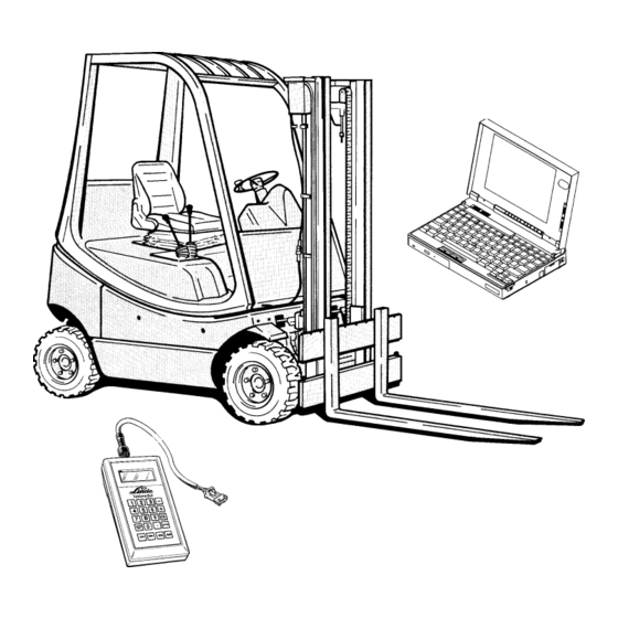
As traction and speed are controlled electrically and hydraulically, the check is also divided into electric and hydraulic tests. For the diagnostics of the electrical system, the Linde test module or a PC (Laptop) is required. The hydraulic test case is required for the check of the hydraulic section. -
Page 57: Working With The Linde Test Module
Section Service Training Page 2.10.1.1 WORKING WITH THE LINDE TEST MODULE Conditions - Traction wheels of truck off the ground - Accelerator pedals in neutral position - Brake pedal held in braking position - Ignition switched off Before using the Test Module, check if it is operational by pressing the EIN (ON) button. The following... -
Page 58: Diagnostics With A Pc And The Linde Interface Converter
(Lamp and cable connection self-test.) The lamp will go off when the engine is running. 2.10.1.2 DIAGNOSTICS WITH A PC AND THE LINDE INTERFACE CONVERTER System requirements for the PC or the notebook: Operating system: MS-DOS 5.0 or higher must be installed Microsoft Windows 3.10 or higher can be installed... -
Page 59: 2.10.1.2.1 Linde Interface Converter
The second 6 pole AMP connector is used for connection to other Linde vehicles (E 10, P 60) which are equipped with a Zapi control system. This latter system has a serial electrical interface for data transfer. -
Page 60: 2.10.1.2.3 Selecting The Linde Program
- E.g. For an installation in German on serial interface COM1, type the following command; UPDATE A: C: 1 1 and press ENTER. - Insert diskette 2 when prompted and press the RETURN key. 2.10.1.2.3 SELECTING THE LINDE PROGRAM - Go to the DOS operating system (root directory c:\). - Enter cd lindiag.dos. -
Page 61: 2.10.1.2.4 Starting The Diagnostic Program "Test & Setup
1.5-P, select the LHC controller. - The selected model (controller type) is identified with the arrow. - Press the ENTER key. - The Linde diagnostic program starts. SELECTION WINDOW UP TO SOFTWARE VERSION 1.4 Linde AG Equipment Program Selection Test&Setup... -
Page 62: Linde Diagnostic Program
Depending on the installed diagnostic program (master program or service program), different window menus can be displayed. The service program permits the same menus as in the Linde diagnostic module to be displayed. The Master program (identified by M) permits additional menus to be displayed. Information on the diagnostic program installed on the computer is displayed at the bottom of the computer window. - Page 63 Section Service Training 02.01 Page INTERFACE CONVERTER STATUS This symbol, two connectors, appears to the right of the serial interface symbol at the bottom of the computer window. When the interface converter is correctly installed and correctly operating, the two plugs are together and green in colour.
-
Page 64: 2.10.1.3.1 Help Function
Section Service Training Page 2.10.1.3.1 HELP FUNCTION When the F1 key is pressed a help text is displayed in the lower part of the computer window explaining the meaning of the individual keys. Keys PgUp é and PgDn ê serve to scroll the help text. The text is selected by using a scroll bar. - Page 65 Section Service Training Page The following table provides a summary of important keys on the Linde diagnostic module and PC. FUNCTIONS OF THE KEYS Module Key PC Key Function Cursor é up + (Plus) Increase value Cursor ê down - (Minus)
- Page 66 Section Service Training 02.01 Page ERROR HANDLING An error is detected as such by the processor only if it is applied for a minimum period (mostly 200 ms). In this way, brief and non-critical error events due to signal noise or delays in the sensing elements are not taken into consideration.
-
Page 67: Overview Of Menu Windows - Lhc Software Version 1.1
Section Service Training 02.01 Page 2.10.1.3.2 OVERVIEW OF MENU WINDOWS - LHC SOFTWARE VERSION 1.1 - 1.3 ð ð ð ð ð ð ð ð ð ð ð... -
Page 68: Menu Windows In Detail - Lhc Software Version 1.1
Section Service Training 02.01 Page 2.10.1.3.3 MENU WINDOWS IN DETAIL - LHC SOFTWARE VERSION 1.1 - 1.3 WINDOW 1 INFORMATION ON SOFTWARE VERSION AND TRUCK TYPE ALL SOFTWARE VERSIONS This window displays general information on the truck as detected by the Test Module. 1st line: Controller designation 2nd line:... - Page 69 Section Service Training 02.01 Page CSpl Equipment code Special truck Series truck WINDOW 12 (MASTERVERSION) COMPARISON OF MASTER AND SAFETY PROCESSOR CODES The signals are displayed in pairs (XY) with the following declaration: X is the code read by the master processor Y is the code read by the safety processor In trouble-free operation X always equals Y, with both processors reading the same code.
- Page 70 Section Service Training 02.01 Page WINDOW 2 CURRENT STATUS MESSAGES AND FAULT MESSAGES This window displays a message if driving is restricted or disabled for safety reasons. The messages are displayed only as long as the restriction or problem exists. In case of faults the red warning lamp will flash; in case of wrong driver commands such as depressing the brake pedal, the lamp will not illuminate.
- Page 71 Section Service Training 02.01 Page Fault messages: The following reactions can be witnessed on the truck when a fault occurs: Warning lamp flashing Truck drives at creep speed Truck brakes to a standstill or remains stationary if not yet moving Current only achieves start of pump control All power stages without power Engine goes to low idling speed...
- Page 72 Pump forward current with specified value of pot = 0 Pump reverse current with specified value of pot = 0 FS Pump forward current too high Pump reverse current too high Stimuli for Bosch test not OK Stimuli for Linde test not OK Internal fault in safety processor...
- Page 73 Section Service Training 02.01 Page WINDOW 3 STORED FAULT MESSAGES Window (3) displays all the fault messages stored in the EEPROM. The frequency of each fault is indicated to the right of a colon behind the fault number. The fault counter can only count to 9 maximum. These fault messages are stored permanently independent of turning the ignition on and off.
- Page 74 Pump forward current with pot setting = 0 Pump reverse current with pot setting = 0 Pump forward current too high Pump reverse current too high Stimuli for Bosch test not OK Stimuli for Linde test not OK Internal fault in safety processor...
- Page 75 Section Service Training 02.01 Page WINDOW 31 CLEARING THE FAULT MESSAGES IN WINDOW 3 With the CE key it is possible to clear the faults shown in window 3; at the same time a slash "/" appears in window 32 behind the last fault after clearing. This slash means: The service engineer has read the faults stored in memory in window 3 and then cleared the memory.
- Page 76 Section Service Training 02.01 Page The fault codes have the following meaning: Fault messages: The following truck responses can occur with individual faults: Warning lamp flashing Truck driving at creep speed Truck brakes to a full stop or remains stationary when not moving Current achieves only start of pump control All power stages are without power engine goes to low idling speed...
- Page 77 Pump reverse current with pot setting = 0 Pump forward current too high Pump reverse current too high Stimuli for Bosch test not OK Stimuli for Linde test not OK Internal fault in safety processor WINDOW 33 (MASTER VERSION) CLEARING WINDOW 32...
- Page 78 Section Service Training 02.01 Page WINDOW 4 INPUTS The switch input signals are displayed in window 4. The switches are numbered and carry the same designation as in the current path diagram. The status of single switches is indicated behind the switch number; for selective switches the status of both channels is displayed.
- Page 79 Section Service Training 02.01 Page 1S2 Lift pressure 0: < 14 bar 1: > 14 bar 1S3 Aux. hydraulics 0: not operated or not connected 1: operated WINDOW 41 (MASTER VERSION) SWITCH SIGNALS OF BOTH PROCESSORS The switching states are indicated by the digits 0 and 1: 0: contact open 1: contact closed The signals are displayed in pairs (XY) with following declaration:...
- Page 80 Section Service Training 02.01 Page WINDOW 5 OUTPUT SIGNALS Window 5 displays the output signals. The indicated components are numbered and correspond to the designation in the wiring diagram. Fault lamps Safety relay in electronic controller Stop light Release valve Flashing light during reversing Fuel shutoff valve Reversing light...
- Page 81 Section Service Training 02.01 Page 5K11 Flashing light during reversing 5K11:0 Flashing light off 5K11:0/1 Flashing light on alternately 5K12 Reversing light 5K12:0 Light off 5K12:1 Light on NOTE: Optional equipment can be connected via outputs 5K10, 11, and 12. WINDOW 51 (MASTER VERSION) ADDITIONAL INFORMATION ON OUTPUTS The switching states are indicated by the digits 0 and 1:...
- Page 82 Section Service Training 02.01 Page 1Y4s Status of release valve power stage 1Y5s Status of gas shutoff valve NOTE: For 1Y5s status has the following meaning: Input Status Output Normal function Open load Overtemperature...
- Page 83 Section Service Training 02.01 Page WINDOW 6 ANALOGUE SIGNALS Window 6 displays the analogue values for the travel and RPM control. Engine RPM Supply voltage Current for engine operating magnet Pot 1 value Pump forward current Pot 2 value Pump reverse current TEST CONDITIONS FOR MEASURING ANALOGUE VALUES VS - V1C AND V2C - Accelerator pedal in neutral position - Brake pedal released...
- Page 84 Section Service Training 02.01 Page TEST CONDITIONS FOR MEASURING VALUES NB1 (ENGINE RPM) AND IY1 (OPERATING MAGNET) - Accelerator pedals released - Brake pedal depressed - Engine idling nB1 Engine RPM Low idling speed: 970 - 1030 rpm Maximum RPM with accelerator fully depressed: 2250 - 2350 rpm Current of engine operating magnet Depending on the position of the accelerator pedals and engine load: i...
- Page 85 Section Service Training 02.01 Page WINDOW 61 (MASTER VERSION) ANALOGUE VALUES (MASTER AND SAFETY PROCESSOR) The analogue readings shown here have the following meaning: vs: Pot power supply read by 2nd processor v1: Pot 1B2.1 read by 1st processor iY1: Pump forward current read by 1st processor iY2: Pump reverse current read by 1st processor The analogue readings of both processors must correspond as much as possible.
- Page 86 Section Service Training 02.01 Page WINDOW 7 SETTING TRUCK SPEED AND SPECIFIED RPM This window displays the parameters specified by the controller. These parameters can be modified up to certain limits. Maximum speed in km/h Tilting RPM, switch 6 bar Engine RPM Lifting RPM, switch 14 bar swashplate angle in %...
- Page 87 Section Service Training 02.01 Page WINDOW 72 (MASTER VERSION) SEAT SWITCH AND MAXIMUM PUMP CURRENT t1S8 Specified time after which the seat switch function becomes active iY2x Maximum current for the pump forward control magnet (standard 1180 mA) iY3x Maximum current for the pump reverse control magnet (standard 1180 mA) WINDOW 73 (MASTER VERSION) RESETTING PARAMETERS IN WINDOW 72 TO STANDARD FACTORY SETTINGS...
-
Page 88: Overview Of Menu Windows - Lhc Software Version 1.4 And
Section Service Training 02.01 Page 2.10.1.3.4 OVERVIEW OF MENU WINDOWS - LHC SOFTWARE VERSION 1.4 AND 1.5 ð ð ð ð ð ð ð ð ð ð ð ð ð ð... -
Page 89: Menu Windows In Detail - Lhc Software Version 1.4 And
Section Service Training 02.01 Page 2.10.1.3.5 MENU WINDOWS IN DETAIL - LHC SOFTWARE VERSION 1.4 AND 1.5 WINDOW 1 INFORMATION ON SOFTWARE VERSION AND TRUCK TYPE This window displays general information on the truck as detected by the Test Module. 1st line: Controller designation 2nd line:... - Page 90 Section Service Training 02.01 Page CSpl Equipment code Special truck Series truck WINDOW 12 (MASTERVERSION) COMPARISON OF MASTER AND SAFETY PROCESSOR CODES The signals are displayed in pairs (XY) with the following declaration: X is the code read by the master processor Y is the code read by the safety processor In trouble-free operation X always equals Y, with both processors reading the same code.
- Page 91 Section Service Training 02.01 Page WINDOW 2 CURRENT STATUS MESSAGES AND FAULT MESSAGES This window displays a message if driving is restricted or disabled for safety reasons. The messages are displayed only as long as the restriction or problem exists. In case of faults the red warning lamp will flash; in case of wrong driver commands such as depressing the brake pedal, the lamp will not illuminate.
- Page 92 Section Service Training 02.01 Page Fault messages: The following reactions can be witnessed on the truck when a fault occurs: Warning lamp flashing Truck drives at creep speed Truck brakes to a standstill or remains stationary if not yet moving Current only achieves start of pump control All power stages without power Engine goes to low idling speed...
- Page 93 Section Service Training 02.01 Page Invalid series / special version encoding A wrong version was identified (e. g. instead of special version - fixed programmed speed reduction, a series version) Possible cause could be a defective cable loom. Check by measuring the inputs and outputs on the LHC module.
- Page 94 Section Service Training 02.01 Page Travel direction signal encoding is not OK The controller can not sense if it is a single-pedal or two-pedal vehicle. Possible causes: encoding plug (near key switch); travel direction switch not connected or faulty, cable loom (negative signals to LHC box not present, check) -->...
- Page 95 Section Service Training 02.01 Page Possible cause: K1 relay in the LHC module is oxidized, sticking Truck responses: W – B – L Release valve can no longer be activated Release valve 1Y4 can not be activated. --> window 5 Possible causes: open connection in cable loom to the release valve, release valve solenoid defective Truck responses: W –...
- Page 96 Section Service Training 02.01 Page Current for pump reverse solenoid is too low The vehicle detects too low a current value for proportional solenoid iY3 --> window 6 Possible causes: cable loom has an open connection to solenoid iY3, proportional solenoid defective Truck responses: W –...
- Page 97 Section Service Training 02.01 Page Lift and tilt signals incompatible (14 bar before 6 bar) The normal switching sequence, first 1S1 then 1S2, is out of sequence. --> window 4 Possible causes: connectors of both pressure switches 1S1 and 1S2 are interchanged, pressure switch 1S1 defective, cable loom from pressure switch 1S1 has an open connection.
- Page 98 Section Service Training 02.01 Page WINDOW 3 STORED FAULT MESSAGES Window (3) displays all the fault messages stored in the EEPROM. The frequency of each fault is indicated to the right of a colon behind the fault number. The fault counter can only count to 9 maximum. These fault messages are stored permanently independent of turning the ignition on and off.
- Page 99 Section Service Training 02.01 Page Error number Not calibrated A new LHC control module was installed in the vehicle so that the reference value of the potentiometer must be transmitted to the module. --> window 8 (calibration) NOTE: If the LHC module is not supplied with electric power for several hours, error code 19 can appear -->...
- Page 100 Section Service Training 02.01 Page The voltage values of potentiometers 1B2.1 and 1B2.2 do not match, and neither is 0 V. The values supplied by both potentiometers are not within the admissible tolerance range. Possible cause: potentiometer The voltage value of potentiometer 1B2.1 is either too low or too high. The voltage value supplied by potentiometer 1B2.1 is not within the admissible range.
- Page 101 Section Service Training 02.01 Page Seat switch breaker and maker have the same signal The seat switch is activated --> window 72 and both output signals of the seat switch show the same value 00 or 11. --> window 4 Possible causes: seat switch is switched active but not connected;...
- Page 102 Section Service Training 02.01 Page Current of solenoid for IC engine is too low The vehicle detects too low a current value for solenoid iY1 to speed controller --> window 6 Possible causes: cable loom has an open connection to solenoid iY1, solenoid defective. Truck responses: W –...
- Page 103 Section Service Training 02.01 Page Sudden change in RPM signal from over 800 to 0 rpm The vehicle no longer detects any engine speed, although the engine was not shut down with the ignition key. Possible causes: speed sensor 1B1 defective, cable loom to the speed sensor has an open connection Truck response: W Tilt pressure signal of 6 bar without RPM...
- Page 104 Section Service Training 02.01 Page WINDOW 31 STORED ERRORS In window 31 (press key 3 and 1) the faults remain stored. The controller will set a slash at the end of the fault codes and all malfunctions occurring thereafter will be shown again behind the slash. Fault number Fault frequency Sign showing fault was acknowledged by service engineer...
- Page 105 Section Service Training 02.01 Page Error number Not calibrated A new LHC control module was installed in the vehicle so that the reference value of the potentiometer must be transmitted to the module. --> window 8 (calibration) NOTE: If the LHC module is not supplied with electric power for several hours, error code 19 can appear -->...
- Page 106 Section Service Training 02.01 Page The voltage values of potentiometers 1B2.1 and 1B2.2 do not match, and neither is 0 V. The values supplied by both potentiometers are not within the admissible tolerance range. Possible cause: potentiometer The voltage value of potentiometer 1B2.1 is either too low or too high. The voltage value supplied by potentiometer 1B2.1 is not within the admissible range.
- Page 107 Section Service Training 02.01 Page Seat switch breaker and maker have the same signal The seat switch is activated --> window 72 and both output signals of the seat switch show the same value 00 or 11. --> window 4 Possible causes: seat switch is switched active but not connected;...
- Page 108 Section Service Training 02.01 Page Current of solenoid for IC engine is too low The vehicle detects too low a current value for solenoid iY1 to speed controller --> window 6 Possible causes: cable loom has an open connection to solenoid iY1, solenoid defective. Truck responses: W –...
- Page 109 Section Service Training 02.01 Page Sudden change in RPM signal from over 800 to 0 rpm The vehicle no longer detects any engine speed, although the engine was not shut down with the ignition key. Possible causes: speed sensor 1B1 defective, cable loom to the speed sensor has an open connection Truck response: W Tilt pressure signal of 6 bar without RPM...
- Page 110 Section Service Training 02.01 Page WINDOW 32 (MASTER VERSION) CLEARING WINDOW 31 The errors indicated in window 31 can be cleared with the “CE“ key.
- Page 111 Section Service Training 02.01 Page WINDOW 4 INPUTS The switch input signals are displayed in window 4. The switches are numbered and carry the same designation as in the current path diagram. The status of single switches is indicated behind the switch number; for selective switches the status of both channels is displayed.
- Page 112 Section Service Training 02.01 Page 1S2 Lift pressure 0: < 14 bar 1: > 14 bar 1S3 Aux. hydraulics 0: not operated or not connected 1: operated WINDOW 41 (MASTER FUNCTION) SWITCH SIGNALS OF BOTH PROCESSORS The switching states are indicated by the digits 0 and 1: 0: contact open 1: contact closed The signals are displayed in pairs (XY) with following declaration:...
- Page 113 Section Service Training 02.01 Page WINDOW 5 OUTPUT SIGNALS Window 5 displays the output signals. The indicated components are numbered and correspond to the designation in the wiring diagram. Fault lamps Safety relay in electronic controller Stop light Release valve Flashing light during reversing Fuel shutoff valve Reversing light...
- Page 114 Section Service Training 02.01 Page 5K11 Flashing light during reversing 5K11:0 Flashing light off 5K11:0/1 Flashing light on alternately 5K12 Reversing light 5K12:0 Light off 5K12:1 Light on NOTE: Optional equipment can be connected via outputs 5K10, 11 and 12. WINDOW 51 (MASTER VERSION) ADDITIONAL INFORMATION ON OUTPUTS The switching states are indicated by the digits 0 and 1:...
- Page 115 Section Service Training 02.01 Page 1Y4s Status of release valve power stage 1Y5s Status of gas shutoff valve NOTE: For 1Y5s status has the following meaning: Input Status Output Normal function Open load Overtemperature...
- Page 116 Section Service Training 02.01 Page WINDOW 6 ANALOGUE SIGNALS Window 6 displays the analogue values for the travel and RPM control. Voltage behind relay contact K1 Engine RPM in the LHC module Current for engine operating magnet Power supply Pump forward current Potentiometer actual Pump reverse current value in %...
- Page 117 Section Service Training 02.01 Page TEST CONDITIONS FOR MEASURING VALUES NB1 (ENGINE RPM) AND IY1 (OPERATING MAGNET) - Accelerator pedals released - Brake pedal depressed - Engine idling nB1 Engine RPM Low idling speed: 970 - 1030 rpm Maximum RPM with accelerator fully depressed: 2250 - 2350 rpm Current of engine operating magnet Depending on the position of the accelerator pedals and engine load: i...
- Page 118 Section Service Training 02.01 Page WINDOW 61 (MASTER VERSION) ADDITIONAL INFORMATION 1 TO ANALOGUE READINGS The analogue readings shown here have the following meaning: Potentiometer supply voltage ± 200 mV Potentiometer voltage 1B2.1 in mV (physical) Potentiometer actual voltage in % (-100 (reverse) up to + 100 (forwards)) v1 + v2: Potentiometer voltage 1B2.1 and 1B2 (desired value 9 - 11 V) with a supply of 10 V...
- Page 119 Section Service Training 02.01 Page WINDOW 7 SETTING TRUCK SPEED AND SPECIFIED RPM This window displays the parameters specified by the controller. These parameters can be modified up to certain limits. Maximum speed in km/h Tilting RPM, switch 6 bar Engine RPM Lifting RPM, switch 14 bar swashplate angle in %...
- Page 120 Section Service Training 02.01 Page WINDOW 72 (MASTER VERSION) SEAT SWITCH AND ACCELERATION accl Deceleration is adjustable from 90 to 120 (in steps of 10) toff Truck shutdown after XX seconds (10 - 500, in steps of 10) tbrk Truck brakes after XX seconds (1 - 20, in steps of 1) NOTE: To use these functions, a seat switch must be installed.
- Page 121 Section Service Training 02.01 Page WINDOW 74 (MASTER VERSION) MAXIMUM TRUCK SPEED vlim: Indication of the factory-set maximum truck speed. Can not be modified! WINDOW 75 (MASTER VERSION) SETTINGS FOR CONTROL MAGNET (MOVING OFF AND FINAL VALUES) iY2s: Transition current for pump forward, adjustable (420 - 480, in steps of 10) iY2e: Final current value for pump forwards, adjustable (1120 - 1200, in steps of 10) iY3s: Transition current for pump reverse, adjustable (420 - 480, in steps of 10) iY3e: Final current value for pump reverse, adjustable (1120 - 1200, in steps of 10)
- Page 122 Section Service Training 02.01 Page WINDOW 76 (MASTER VERSION) RESETTING THE PARAMETERS OF WINDOW 75 TO STANDARD FACTORY SETTING The parameters are reset by pressing the <CE> key. WINDOW 8 ADJUSTMENT OF TRACTION POTENTIOMETER Potentiometer voltage 1B2.1 (physical) Potentiometer actual value in %, adjustable as long as "OK" is displayed For the calibration of the traction potentiometer the brake pedal must be depressed and the ignition switched on.
-
Page 123: Overview Of Menu Windows - Lhc Software Version
Section Service Training 02.01 Page 2.10.1.3.6 OVERVIEW OF MENU WINDOWS - LHC SOFTWARE VERSION 1.6 ð ð ð ð ð ð ð ð ð ð ð ð ð ð... -
Page 124: Menu Windows In Detail - Lhc Software Version
Section Service Training 02.01 Page 2.10.1.3.7 MENU WINDOWS IN DETAIL - LHC SOFTWARE VERSION 1.6 WINDOW 1 INFORMATION ON SOFTWARE VERSION AND TRUCK TYPE This window displays general information on the truck as detected by the Test Module. 1st line: Controller designation 2nd line: Software version of both processors... - Page 125 Section Service Training 02.01 Page CSpl Equipment code Special truck -> not displayed on all trucks or not supported Series truck WINDOW 12 (MASTERVERSION) COMPARISON OF MASTER AND SAFETY PROCESSOR CODES The signals are displayed in pairs (XY) with the following declaration: X is the code read by the master processor Y is the code read by the safety processor In trouble-free operation X always equals Y, with both processors reading the same code.
- Page 126 Section Service Training 02.01 Page WINDOW 2 CURRENT STATUS MESSAGES AND FAULT MESSAGES This window displays a message if driving is restricted or disabled for safety reasons. The messages are displayed only as long as the restriction or problem exists. In case of faults the red warning lamp will flash; in case of wrong driver commands such as depressing the brake pedal, the lamp will not illuminate.
- Page 127 Section Service Training 02.01 Page Fault messages: The following reactions can be witnessed on the truck when a fault occurs: Warning lamp flashing Truck drives at creep speed Truck brakes to a standstill or remains stationary if not yet moving Current only achieves start of pump control All power stages without power Engine goes to low idling speed...
- Page 128 Section Service Training 02.01 Page Invalid series / special version encoding A wrong version was identified (e. g. instead of special version - fixed programmed speed reduction, a series version) Possible cause could be a defective cable loom. Check by measuring the inputs and outputs on the LHC module.
- Page 129 Section Service Training 02.01 Page Travel direction signal encoding is not OK The controller can not sense if it is a single-pedal or two-pedal vehicle. Possible causes: encoding plug (near key switch); travel direction switch not connected or faulty, cable loom (negative signals to LHC box not present, check) -->...
- Page 130 Section Service Training 02.01 Page Release valve can no longer be activated Release valve 1Y4 can not be activated. --> window 5 Possible causes: open connection in cable loom to the release valve, release valve solenoid defective Truck responses: W – B Release valve can no longer be deactivated Release valve 1Y4 was activated, but can no longer be deactivated.
- Page 131 Section Service Training 02.01 Page Current for pump reverse solenoid is too low The vehicle detects too low a current value for proportional solenoid iY3 --> window 6 Possible causes: cable loom has an open connection to solenoid iY3, proportional solenoid defective Truck responses: W –...
- Page 132 Section Service Training 02.01 Page Lift and tilt signals incompatible (14 bar before 6 bar) The normal switching sequence, first 1S1 then 1S2, is out of sequence. --> window 4 Possible causes: connectors of both pressure switches 1S1 and 1S2 are interchanged, pressure switch 1S1 defective, cable loom from pressure switch 1S1 has an open connection.
- Page 133 Section Service Training 02.01 Page WINDOW 3 STORED FAULT MESSAGES (DISPLAY AND DELETE FUNCTION) Window (3) displays all the fault messages stored in the EEPROM. The frequency of each fault is indicated to the right of a colon behind the fault number. The fault counter can only count to 9 maximum. These fault messages are stored permanently independent of turning the ignition on and off.
- Page 134 Section Service Training 02.01 Page Error number Not calibrated A new LHC control module was installed in the vehicle so that the reference value of the potentiometer must be transmitted to the module. --> window 8 (calibration) NOTE: If the LHC module is not supplied with electric power for several hours, error code 19 can appear -->...
- Page 135 Section Service Training 02.01 Page The voltage values of potentiometers 1B2.1 and 1B2.2 do not match, and neither is 0 V. The values supplied by both potentiometers are not within the admissible tolerance range. Possible cause: potentiometer The voltage value of potentiometer 1B2.1 is either too low or too high. The voltage value supplied by potentiometer 1B2.1 is not within the admissible range.
- Page 136 Section Service Training 02.01 Page Seat switch breaker and maker have the same signal The seat switch is activated --> window 72 and both output signals of the seat switch show the same value 00 or 11. --> window 4 Possible causes: seat switch is switched active but not connected;...
- Page 137 Section Service Training 02.01 Page Current of solenoid for IC engine is too low The vehicle detects too low a current value for solenoid iY1 to speed controller --> window 6 Possible causes: cable loom has an open connection to solenoid iY1, solenoid defective. Truck responses: W –...
- Page 138 Section Service Training 02.01 Page Sudden change in RPM signal from over 800 to 0 rpm The vehicle no longer detects any engine speed, although the engine was not shut down with the ignition key. Possible causes: speed sensor 1B1 defective, cable loom to the speed sensor has an open connection Truck response: W Tilt pressure signal of 6 bar without RPM...
- Page 139 Section Service Training 02.01 Page WINDOW 31 STORED ERRORS (DISPLAY AND DELETE FUNCTION) In window 31 (press key 3 and 1) the faults remain stored. The controller will set a slash at the end of the fault codes and all malfunctions occurring thereafter will be shown again behind the slash. Fault number Fault frequency Sign showing fault was acknowledged by service engineer...
- Page 140 Section Service Training 02.01 Page Test conditions: Battery min. 11.3 V Potentiometer calibration --> window 8 NOTE: If no calibration is possible, there may be a problem with the pedal mechanism in addition to a defective potentiometer. Error number Not calibrated A new LHC control module was installed in the vehicle so that the reference value of the potentiometer must be transmitted to the module.
- Page 141 Section Service Training 02.01 Page Pressure switch and pressure sensor signals are both active The switch and sensor signal at pressure sensor 1B10 are applied simultaneously. Possible cause: defective pressure sensor Truck responses: W Pressure switch active although engine speed is zero A switch signal 1B10 is applied although IC engine was not started and therefore no RPM are indicated.
- Page 142 Section Service Training 02.01 Page Brake switch 1 (1S5) breaker and maker have the same signal. The brake switch does not change its outputs from 0 to 1 and from 1 to 0. --> window 4 Possible causes: brake switch defective, open connection (check negative signals coming from brake switch to LHC module) Truck responses: W –...
- Page 143 Section Service Training 02.01 Page Current of release valve is too low Release valve 1Y4 can not be activated --> window 5 Possible causes: inherent resistance of solenoid of valve 1Y4 is too large or solenoid not connected; cable loom Truck responses: W –...
- Page 144 Section Service Training 02.01 Page Current for gas shutoff valve is too low The vehicle detects too low a current value at the solenoid for gas shutoff valve 1Y5 Possible causes: cable loom has an open connection to solenoid 1Y5 of the gas shutoff valve or in the solenoid Truck response: W Status of release valve...
- Page 145 Section Service Training 02.01 Page NOTE: If there is a single error code between 70 - 99, the LHC module can be assumed to be defective. If further codes under 70 are detected, these must be considered first. NOTE: If there is no diagnostic output of module LHC 1N2 and/or the vehicle can not be started, and/ or the warning lamp is not on, LHC module 1N2 can be assumed to be defective if the following conditions are fulfilled: - Fuse 1F17 and 1F18 are OK...
- Page 146 Section Service Training 02.01 Page WINDOW 4 INPUTS The switch input signals are displayed in window 4. The switches are numbered and carry the same designation as in the current path diagram. The status of single switches is indicated behind the switch number; for selective switches the status of both channels is displayed.
- Page 147 Section Service Training 02.01 Page 1S2 Lift pressure 0: < 14 bar 1: > 14 bar 1S3 Aux. hydraulics 0: not operated or not connected 1: operated WINDOW 41 (MASTER VERSION) SWITCH SIGNALS OF BOTH PROCESSORS The switching states are indicated by the digits 0 and 1: 0: contact open 1: contact closed The signals are displayed in pairs (XY) with following declaration:...
- Page 148 Section Service Training 02.01 Page WINDOW 5 OUTPUT SIGNALS ALL SOFTWARE VERSIONS Window 5 displays the output signals. The indicated components are numbered and correspond to the designation in the wiring diagram. Fault lamps Safety relay in electronic controller Stop light Release valve Flashing light during reversing Fuel shutoff valve...
- Page 149 Section Service Training 02.01 Page 5K11 Flashing light during reversing 5K11:0 Flashing light off 5K11:0/1 Flashing light on alternately 5K12 Reversing light 5K12:0 Light off 5K12:1 Light on NOTE: Optional equipment can be connected via outputs 5K10, 11 and 12. WINDOW 51 (MASTER VERSION) ADDITIONAL INFORMATION ON OUTPUTS The switching states are indicated by the digits 0 and 1:...
- Page 150 Section Service Training 02.01 Page WINDOW 6 ANALOGUE SIGNALS Window 6 displays the analogue values for the travel and RPM control. Voltage behind relay contact K1 Engine RPM in the LHC module Current for engine operating magnet Power supply Pump forward current Potentiometer actual Pump reverse current value in %...
- Page 151 Section Service Training 02.01 Page TEST CONDITIONS FOR MEASURING VALUES NB1 (ENGINE RPM) AND IY1 (OPERATING MAGNET) - Accelerator pedals released - Brake pedal depressed - Engine idling nB1 Engine RPM Low idling speed: 970 - 1030 rpm Maximum RPM with accelerator fully depressed: 2250 - 2350 rpm Current of engine operating magnet Depending on the position of the accelerator pedals and engine load: i...
- Page 152 Section Service Training 02.01 Page WINDOW 61 (MASTER VERSION) ADDITIONAL INFORMATION 1 TO ANALOGUE READINGS The analogue readings shown here have the following meaning: Potentiometer supply voltage ± 200 mV Potentiometer voltage 1B2.1 in mV (physical) Potentiometer actual voltage in % (-100 (reverse) up to + 100 (forwards)) v1 + v2: Potentiometer voltage 1B2.1 and 1B2 (desired value 9 - 11 V) with a supply of 10 V...
- Page 153 Section Service Training 02.01 Page WINDOW 7 SETTING TRUCK SPEED AND SPECIFIED RPM This window displays the parameters specified by the controller. These parameters can be modified up to certain limits. Maximum speed in km/h Tilting RPM, switch 6 bar Engine RPM Lifting RPM, switch 14 bar swashplate angle in %...
- Page 154 Section Service Training 02.01 Page WINDOW 72 (MASTER VERSION) SEAT SWITCH AND ACCELERATION accl Deceleration is adjustable from 100 to 120 (in steps of 10) toff Truck shutdown after XX seconds (10 - 500, in steps of 10) tbrk Truck brakes after XX seconds (1 - 20, in steps of 1) (To use this function, a seat switch must be installed.
- Page 155 Section Service Training 02.01 Page WINDOW 74 (MASTER VERSION) MAXIMUM TRUCK SPEED vlim: Indication of the factory-set maximum truck speed. Can not be modified! WINDOW 75 (MASTER VERSION) SETTINGS FOR CONTROL MAGNET (MOVING OFF AND FINAL VALUES) iY2s: Transition current for pump forward, adjustable (420 - 480, in steps of 10) iY2e: Final current value for pump forwards, adjustable (1120 - 1200, in steps of 10) iY3s: Transition current for pump reverse, adjustable (420 - 480, in steps of 10) iY3e: Final current value for pump reverse, adjustable (1120 - 1200, in steps of 10)
- Page 156 Section Service Training 02.01 Page WINDOW 76 (MASTER VERSION) RESETTING THE PARAMETERS OF WINDOW 75 TO STANDARD FACTORY SETTING The parameters are reset by pressing the <CE> key. WINDOW 8 ADJUSTMENT OF TRACTION POTENTIOMETER Potentiometer voltage 1B2.1 (physical) Potentiometer actual value in %, adjustable as long as "OK" is displayed For the calibration of the traction potentiometer the brake pedal must be depressed and the ignition switched on.
- Page 157 Section Service Training 02.01 Page...
-
Page 158: Hydraulic System Diagnostics
Section Service Training 02.01 Page 2.10.2 HYDRAULIC SYSTEM DIAGNOSTICS 2.10.2.1 CIRCUIT DIAGRAM AND OVERVIEW FOR DIAGNOSTICS... - Page 159 Section Service Training 02.01 Page 1 Tandem pump 2 Bypass valve 3 Hydraulic variable pump HPV 55 -02 4 Test port - servo piston "Y" 5 Test port F" - pilot pressure upstream of release valve 6 Test port - servo piston "Z" 7 Test ports - (HP) 8 Hydraulic damper 9 Steering control valve...
-
Page 160: Test Aids
Section Service Training 02.01 Page 2.10.2.2 TEST AIDS The screw couplings, adapters, test lines and pressure gauges required for the measurements are contained in the test case. 2.10.2.2.1 EXPLANATIONS TO TROUBLESHOOTING The functional tests and any ensuing troubleshooting is performed separately for each main group. The following components and functions are affected: Hydraulic steering system Section 2.10.2.3... - Page 161 Section Service Training 02.01 Page OVERVIEW OF PRESSURE READINGS (APPROXIMATE VALUES) Position of accelerator pedal Position of brake pedal Test point Pressure (bar) Zero position released 17.5 Zero position depressed F” Depressed approx. 20 mm released F” 17.5 F pedal fully depressed released 17.5 R pedal fully depressed...
-
Page 162: Power-Assisted Steering
Section Service Training 02.01 Page 2.10.2.3 POWER-ASSISTED STEERING Two different methods can be used to locate a malfunction in the steering system. 2.10.2.3.1 TROUBLESHOOTING WITHOUT MEASUREMENT OF BOOST AND MAXIMUM PRESSURE TEST REQUIREMENTS - Travel drive must be functioning TEST Test Symptoms Assessment... - Page 163 Section Service Training 02.01 Page With engine at idling speed, turn the steering wheel to the right and left through the full cycle, hold it briefly and assess operation according to the following evaluation table: Symptoms Readings Assessment 1. Stiff steering. HP less than Safety valve of 120 bar.
-
Page 164: Hydraulic Brake System
Section Service Training 02.01 Page 2.10.2.4 HYDRAULIC BRAKE SYSTEM 2.10.2.4.1 FUNCTIONAL TEST TEST REQUIREMENTS - Truck blocked up and secured so that both drive wheels can rotate freely. - Pedals properly adjusted. - Brake pedal locked in position "brake applied". TEST Test Symptoms... - Page 165 Section Service Training 02.01 Page Screw in low pressure gauge into port F of pressure filter. Start the engine and read the pressure on gauge. Pressure min. 17.5 bar. Plug port E at brake valve with a blanking plug and repeat the test. Check "Hydrostatic Travel Brake valve defective.
- Page 166 Section Service Training 02.01 Page Plug port BR at the brake valve. Start the engine, release the brake, fully depress the F or R pedal. The brake of the turning wheel is not in order. Drive wheels rotate. Braking system in order. Remove and remedy the fault.
-
Page 167: Hydrostatic Travel Drive
Section Service Training 02.01 Page 2.10.2.5 HYDROSTATIC TRAVEL DRIVE 2.10.2.5.1 TROUBLESHOOTING TEST CONDITIONS - Truck blocked up and secured so that both traction wheels can rotate freely. - Power steering functioning. - Brake pedal locked in position "brake applied". - Electronic controller does not indicate an error (warning lamp not flashing). - Engine can not be started. - Page 168 Section Service Training 02.01 Page Connect LP pressure gauge to port F, engine at idling speed, brake applied. LP approx. 17.5 bar Seal port E with blanking plug, repeat measurements. Fault in the braking Pressure now system. See "Hydraulic approx. 17.5 bar Braking System".
- Page 169 Section Service Training 02.01 Page Connect the electric diagnostic unit to the test connector. Connect the LP pressure gauge to port F" (release valve). Line reconnected to port E. Start the engine, open window 5 and release the brake, depress the F or R pedal until 1Y4 is activated.
- Page 170 Section Service Training 02.01 Page Wheels start rotating at i = 440 - 460 mA. Adjust start of control, see "Start of Pump Control". Check hydraulic servo Start of control can be control adjusted. Fully depress the forward pedal. Perform electrical sys. iY2 approx.
- Page 171 Section Service Training 02.01 Page Check swash angle of Average wheel variable pump, see speed OK. "Swash angle of the va- riable pump". Connect LP pressure gauge to port F", HP pressure gauge to HP test point (on right side). Block the brake (with brake release valve by pressing brake piston down with a long screwdriver), depress the forward pedal, read HP and LP.
- Page 172 Section Service Training 02.01 Page...
-
Page 173: Steering System
Section Service Training Page STEERING SYSTEM SCHEMATIC DIAGRAM OF THE STEERING SYSTEM 1 Gear pump A Working hydraulics 2 Pressure relief valve 120 bar B Feed 3 Steering valve 45 cm³ 4 Make-up valve 5 Hose safety valves 190 bar... - Page 174 Section Service Training Page...
-
Page 175: Controls
Section Service Training Page CONTROLS... -
Page 176: Pedal Stroke Adjustment Instructions
Section Service Training Page PEDAL STROKE ADJUSTMENT INSTRUCTIONS... - Page 177 Section Service Training Page 1 Forward stop screw 2 Reverse stop screw 3 Microswitch 2 4 Stop screw for limiting pedal stroke upwards (forward pedal) 5 Spacer, thickness = 3 mm CONDITIONS - Pedals mechanically in good working order. - Traction pot 1B2 and brake switches 1S5 and S14 are connected. - Test module connected to interface 6X6.
-
Page 178: Adjustment Instructions For The Speed Control
Section Service Training Page ADJUSTMENT INSTRUCTIONS FOR THE SPEED CONTROL... - Page 179 Section Service Training Page CONDITION Engine is shut down, threaded rod (5) is removed from the control lever (1) along with the ball of the ball- and-socket joint (3). ADJUSTMENT 1 Fasten the ball of the joint (3) in the centre notch of the lever (1). 2 Move the speed control lever (1) by hand against the top idle stop screw (10) and pull the solenoid shaft and threaded rod (5) out completely.
-
Page 180: Engine Speed Sensor Adjustment Instructions
Section Service Training Page ENGINE SPEED SENSOR ADJUSTMENT INSTRUCTIONS NOTE: The engine can not be started if the actual value sensor B1 is removed or connector X1 is separated. ADJUSTMENT - Slacken nuts (1) and (2). - Insert a feeler gauge into the gap at the intermediate housing between gear ring (3) and engine speed sensor B1. -
Page 181: Electrical System
Section Service Training 02.01 Page ELECTRICAL SYSTEM BASIC DIAGRAM DIESEL VERSION Glow duration unit 45 - 49 Fan controller 80 -95 Actual speed sensor 101 - 103 Accelerator double potentiometer 116 - 121 1B10 Pressure sensor 112 - 114 Fuse 50 A Fuse 5 A Fuse 5 A Fuse 15 A... - Page 182 Section Service Training 02.01 Page 9R1/2/3 Resistor 81, 86, 91 Fan resistor Ignition switch 7 - 12 Coolant temperature switch Oil temperature switch Engine oil pressure switch Suction filter vacuum switch Fuel level warning light switch (option) Brake pedal switch 2 (Start inhibit) Pressure switch (6 bar) Pressure switch (14 bar) Brake pedal switch 1...
- Page 183 Section Service Training 02.01 Page BASIC DIAGRAM DIESEL VERSION, H 12/16/18/20 D-03, SERIES 350 - WITH PRESSURE SWITCHES...
- Page 184 Section Service Training 02.01 Page BASIC DIAGRAM DIESEL VERSION, H 12/16/18/20 D-03, SERIES 350 - WITH PRESSURE SWITCHES...
- Page 185 Section Service Training 02.01 Page BASIC DIAGRAM DIESEL VERSION, H 12/16/18/20 D-03, SERIES 350 - WITH PRESSURE SENSOR...
- Page 186 Section Service Training 02.01 Page BASIC DIAGRAM DIESEL VERSION, H 12/16/18/20 D-03, SERIES 350 - WITH PRESSURE SENSOR...
-
Page 187: Basic Diagram Lpg Version
Section Service Training 02.01 Page BASIC DIAGRAM LPG VERSION Ignition controller 45 - 48 Fan controller 54 - 70 Actual speed sensor 104, 105 Accelerator double potentiometer 122 - 127 1B10 Pressure sensor 118 - 120 1E40 Distributor 42 - 48 1E41 Spark plugs 42 - 45... - Page 188 Section Service Training 02.01 Page Ignition switch 9 - 13 Coolant temperature switch Oil temperature switch Engine oil pressure switch Suction filter vacuum switch Fuel level warning light switch (option) Brake pedal switch 2 (Start inhibit) Pressure switch (6 bar) Pressure switch (14 bar) Brake pedal switch 1 1S25...
- Page 189 Section Service Training 02.01 Page BASIC DIAGRAM LPG VERSION, H 12/16/18/20 T-03, SERIES 350 - WITH PRESSURE SWITCHES...
- Page 190 Section Service Training 02.01 Page BASIC DIAGRAM LPG VERSION, H 12/16/18/20 T-03, SERIES 350 - WITH PRESSURE SWITCHES...
- Page 191 Section Service Training 02.01 Page BASIC DIAGRAM LPG VERSION, H 12/16/18/20 T-03, SERIES 350 - WITH PRESSURE SENSOR...
- Page 192 Section Service Training 02.01 Page BASIC DIAGRAM LPG VERSION, H 12/16/18/20 T-03, SERIES 350 - WITH PRESSURE SENSOR...
-
Page 193: Diagram For Optional Equipment
Section Service Training 02.01 Page DIAGRAM FOR OPTIONAL EQUIPMENT Controller (LPG) 130 - 149 Controller particle filter (Diesel) 163 - 187 Servo (LPG) 151, 152 Glow plug current regulator (Diesel) 178 - 179 Diagnostic LED Lambda sensor (LPG) 126, 127 Buzzer (Diesel) 170 - 171 Flame sensor... - Page 194 Section Service Training 02.01 Page Switch light (1.2 W) 9H16 Switch light (1.2 W) 9H17 Switch light (1.2 W) Starter relay 205 - 208 Flasher unit 36 - 38 5K10 Relay for optional equipment 49 - 51, 54 - 56, 59 - 61 Regeneration ihibit relay 160 - 163 Start inhibit relay...
- Page 195 Section Service Training 02.01 Page Connector 2 pins (LPG) Connector 2 pins (Diesel) 182, 183 Diagnostics connector 6 pins 139 - 146 Connector 6 pins 79 - 81 Connector 3 pins 101 - 103 Connector 6 pins 1, 8, 11 Connector 6 pins 5, 7, 13 9X10...
- Page 196 Section Service Training 02.01 Page...
- Page 197 Section Service Training 02.01 Page DIAGRAM FOR OPTIONAL EQUIPMENT, H 12/16/18/20 D-03/T-03, SERIES 350...
- Page 198 Section Service Training 02.01 Page DIAGRAM FOR OPTIONAL EQUIPMENT, H 12/16/18/20 D-03/T-03, SERIES 350...
- Page 199 Section Service Training 02.01 Page DIAGRAM FOR OPTIONAL EQUIPMENT, H 12/16/18/20 D-03/T-03, SERIES 350...
- Page 200 Section Service Training 02.01 Page...
-
Page 201: Layout Of Electrical Installation
Section Service Training 02.01 Page LAYOUT OF ELECTRICAL INSTALLATION Starter relay, 5 A 5F8 Sidelights, right, 5 A Composite instrument, 5 A 5F9 Main fuse, lighting terminal 15, 15 A Ignition system, 15 A 5F10 Main fuse, lighting terminal 30, 15 A Horn and auxiliary relay terminal 15, 10 A 9F4 Wiper, front, 10 A 1F17 Electro-hydraulic control LHC, 1 A... -
Page 202: Composite Instrument
Section Service Training 02.01 Page COMPOSITE INSTRUMENT The composite instrument contains the following control and indicator elements: 1 Hour meter 2 Hour meter ON indicator 3 Engine temperature warning light 4 Hydraulic oil temperature warning light 5 Engine oil pressure warning light 6 Directional indicator light* 7 Battery charge indicator light 8 Fan warning light... - Page 203 Section Service Training 02.01 Page INDICATOR FUNCTION POSSIBLE CAUSE(S) Hour meter (1). Indicates lift truck service hours. NOTE The meter indicates the elapsed The elapsed service hours should be re- service hours of the truck and ser- corded when replacing a faulty hour meter. ves to determine inspection and Record the data on durable tape and affix maintenance intervals.
- Page 204 Section Service Training 02.01 Page...
-
Page 205: Hydraulic System
Section Service Training Page HYDRAULIC SYSTEM SCHEMATIC Service cylinder (auxiliary hydraulics) Service cylinder (auxiliary hydraulics) Tilt cylinder Lift cylinder, standard Slow lowering valve Control valve block, assy., including: Way valve - auxiliary hydraulics Way valve - auxiliary hydraulics Check valve (pilot controlled) Way valve - tilting Way valve - lifting 2/2-way valve (pressure balance) -
Page 206: Sealing Of The Control Valve
Section Service Training Page SEALING OF THE CONTROL VALVE SEALING OF THE CONTROL VALVE SLIDES - Remove the control valve. - Remove the slide cover (3) after the two fastening screws (2) have been screwed out. - Pull the slide (1) out to the bottom, and mount a new seal set. SEALING OF THE VALVE SEGMENTS - Pull out the three tension bolts after the retaining nut M8 has been screwed out. -
Page 207: Setting Of The Pressure-Limiting Valve
Section Service Training Page SETTING OF THE PRESSURE-LIMITING VALVE The pressure-limiting valve (1) is built into the first section of the control valve block. - Connect the pressure test gauge to the working hydraulic unit (pertaining to the type with accessory hydraulic unit, the quick coupling is the best position for this). - Page 208 Section Service Training Page...
-
Page 209: Lpg Model Of Ic-Engined Fork Truck H 12/16/18/20 T-03, Series
Section Service Training 02.01 Page LPG MODEL OF IC-ENGINED FORK TRUCK H 12/16/18/20 T-03, SERIES ENGINE 9.1.1 ENGINE SPECIFICATIONS Engine model VW ADF Number of cylinders Displacement 1781 cc Compression 9 - 12 bar Wear limit 7.5 bar Lower idle speed Upper idle speed 2300 Nominal speed... -
Page 210: Toothed Belt
Section Service Training Page 9.1.2 TOOTHED BELT 9.1.2.1 OVERALL VIEW OF TOOTHED BELT GUARD 11 V-belt pulley 1 Upper toothed belt guard 2 Fastening nut (45 Nm) 12 Fastening screw (20 Nm) 3 Idler pulley 13 V-belt 14 Fastening screw (10 Nm) 4 Toothed belt 5 Fastening screw (30 Nm) 15 Lower toothed belt guard... -
Page 211: Removing, Installing, Tensioning The Toothed Belt
Section Service Training Page 9.1.2.2 REMOVING, INSTALLING, TENSIONING THE TOOTHED BELT REMOVAL - Remove the V-belt, pulley and upper and lower toothed belt guards. - Mark the running direction of the toothed belt. - Loosen the idler pulley and remove the toothed belt. INSTALLATION NOTE: When rotating the camshaft, the crankshaft must... - Page 212 Section Service Training Page - Tension the toothed belt by turning the idler pulley with a spanner (eg Matra V159) in the direction of the arrow. It should just still be possible to twist the toothed belt 90 degrees with the thumb and index finger midway between the camshaft sprocket and intermediate shaft sprocket.
-
Page 213: Adjusting The Alternator V-Belt Tension
Section Service Training Page 9.1.2.3 ADJUSTING THE ALTERNATOR V-BELT TENSION (Only if provided with tensioning bracket.) - Slacken all fastening screws for tensioning bracket -A- and alternator at least one turn. NOTE: It should be easy to move the alternator by hand. - Tighten the V-belt by turning the tensioning nut -B- with a torque wrench Specified tension: 8... -
Page 214: Cylinder Head
Section Service Training Page 9.1.3 CYLINDER HEAD 9.1.3.1 REMOVING AND INSTALLING THE CYLINDER HEAD NOTE: If a replacement cylinder head with camshaft is installed, valve clearances do not need to be adjusted. The contact surface between the bucket tappets and cam faces must be oiled after installation of the head. - Page 215 Section Service Training Page REMOVAL Remove the cylinder head bolts in the given sequence. CHECK THE CYLINDER HEAD FOR FLATNESS Max. deviation allowed : 0.1 mm INSTALLATION Engine cold Pistons not at TDC NOTE: Take the new cylinder head gasket just before installation out of its packaging.
- Page 216 Section Service Training Page Tighten the cylinder head in four stages and in the sequence shown: Pretighten with a torque wrench: Stage I = 40 Nm Stage II = 60 Nm Tighten further with a normal spanner: Stage III = 1/4 turn (90°) Stage IV = 1/4 turn (90°) NOTE: The cylinder head bolts do not need to be...
- Page 217 Section Service Training Page - Remove the rocker cover. - Turn the crankshaft at the sprocket fastening screw until the cams of the tappets to be checked are pointing upwards. - Determine the clearance between cams and tappets. - If the clearance exceeds 0.1 mm, replace the tappet. If the clearance measured is less than 0.1 mm or nil, continue the check as follows: - Press the tappet down with a wooden or plastic wedge.
-
Page 218: Electrical System
Section Service Training Page ELECTRICAL SYSTEM 9.2.1 ELECTRONIC IGNITION DESCRIPTION The engine is provided with a Bosch transistorised coil ignition system (TSZ) with contactless ignition control. Ignition timing without mechanical contacts has the following advantages: - The ignition system and the contact breaker are not subject to wear so that they are completely maintenance-free. -
Page 219: Tsz-H Ignition System (Transistorised Ignition System)
Section Service Training Page 9.2.1.1 TSZ-H IGNITION SYSTEM (TRANSISTORISED IGNITION SYSTEM) 1 Suppressor plug 0.6 - 1.4 kW 14 Trigger wheel 2 Distributor cap 15 Clip 3 Ignition lead 16 Vacuum diaphragm (not connected) 4 Spark plug connector 4 - 6 kW 17 Screw (20 Nm) 5 Carbon contact with spring 18 Terminal... -
Page 220: Safety Measures For Tsz-Hall System
Section Service Training Page 9.2.1.2 SAFETY MEASURES FOR TSZ-HALL SYSTEM In order to avoid injuries to persons and/or damage to the TSZ-Hall System the following must be noted when working on vehicles with the TSZ-Hall System: The ignition must be switched off before any ignition wiring - including HT leads and test appliance leads - is disconnected or connected. - Page 221 Section Service Training Page VERSION A The mark on the ignition timing sprocket must be in line with the rocker cover (arrow). VERSION B The mark on the ignition timing sprocket must in line with the arrow on the toothed belt guard. - Set the take-up journal for the oil pump shaft parallel to the crankshaft.
-
Page 222: Checking And Adjusting The Ignition Timing
Section Service Training Page 9.2.1.4 CHECKING AND ADJUSTING THE IGNITION TIMING - Engine oil temperature minimum 60 °C. - Connect tester for ignition timing and revolution. - Start the engine and run it at idling speed. - Check the ignition timing. Checking with stroboscope: Direct flashes on to the timing mark (3). -
Page 223: Checking The Tsz-H Ignition System
Section Service Training Page 9.2.1.5 CHECKING THE TSZ-H IGNITION SYSTEM TSZ switch unit Ignition switch E40 Distributor with Hall generator Ignition coil Battery IGNITION COIL T1 - Measure the primary resistance between terminals 1 (-) and 15 (+). Desired value: 0.52 to 0.76 W - Measure the secondary resistance between terminals 4 and 15. -
Page 224: Hall Generator
Section Service Training Page 9.2.1.5.1 SWITCH UNIT A1 TEST REQUIREMENT - Ignition coil is in order. TEST - Unhook the clip and disconnect the plug from the TSZ switch unit. - Connect the voltmeter to pins 4 (+) and 2 (-) of the male plug. - Turn on the ignition. - Page 225 Section Service Training Page - Connect the voltmeter between terminal 1(-) and terminal 15 (+) of the ignition coil. - Switch on the ignition. Desired value: min. 2 V, must drop to 0 V after 1 to 2 seconds. If not, replace the TSZ switch unit and test the ignition coil for emerging sealing compound;...
- Page 226 Section Service Training Page 9.2.1.5.2 HALL GENERATOR TEST REQUIREMENTS - TSZ-H switch unit must be in order. - Ignition coil must be in order. - Lead and connections between the TSZ-H switch unit and the distributor must be in order. - Connectors and the attaching parts at the distributor, Hall generator and TSZ-H must be in order.
- Page 227 Section Service Training Page CHECKING THE SPEED LIMITER Check the resistance at the speed limiter contacts. Specified value: 4 - 6 kW. If the specified value is not obtained: renew the speed limiter. CHECKING THE STALL SPEED - Disconnect the lift magnet linkage. - Read the stall speed at the speed limiter.
-
Page 228: Lpg Installation
Section Service Training Page LPG INSTALLATION 9.3.1 SCHEMATIC 1 Air filter 8 Vacuum pipe Mixer - secondary section of vaporizer 2 Ignition switch 3 LPG cylinder 9 Gas pipe Vaporizer - mixer 4 Combined gas cut-off valve 5 Gas pipe 10 Engine 11 Intake manifold Cylinder - shutoff valve... -
Page 229: Lpg Mixer
Section Service Training Page 9.3.2 LPG MIXER MOUNTING - Close the throttle valve. - Block lever (2) at an angle of 25 ° ± 1.5 ° on throttle valve shaft (1). - Install the mixer (3) and fix solenoid (6) on console (7). - Close the throttle valve and set the connecting linkage (5) between solenoid (6) and lever (2) to a pretension of 1 mm. - Page 230 Section Service Training Page ADJUSTING THE "CO" CONTENT Requirements: - Ignition timing is in order, i.e. 18 ° BTDC at 1030 rpm. - Engine and the hydraulic oil at operating temperature. - Pressure-relief valve of working hydraulics set to 220 bar. - Parking brake applied.
- Page 231 Section Service Training Page - Measure the "CO" content with a load on the engine. "CO" content £ 0.06 and 0.08 % Setting: Correction: To reduce the "CO" content = turn adjusting screw (2) to "L". NOTE: During the measurement, the engine speed must not drop below 2300 rpm. If this is the case, a trouble-shooting is required.
- Page 232 Section Service Training Page...
- Page 233 Index Service Training 02.01 Page section/page Injection pump adapter 1/10 Alternator V-belt tension 1/2, 9/5 Basic diagram Diesel version Basic diagram LPG version Check cylinder head for distortion 1/14 Composite instrument 6/22 Compression pressure 1/17 Control valve sealing Controls Crankshaft sprocket Crankshaft 1/2, 9/6 Cylinder head...
- Page 234 Hydrostatic travel drive 2/141 Idling speed adjustment 1/10 Ignition timing 9/14 Injector needle tip (visual check) 1/12 Leakages 1/13 Linde Diagnostic Program 2/36 Linde Interface Converter 2/32, 2/33 Linde Test Module 2/31 LPG engine LPG installation 9/20 LPG mixer 9/21 Menu windows, software version 1.1 - 1.3...
- Page 235 Index Service Training 02.01 Page Menu windows, software version 1.6 2/97, 2/98 Multiple disc brake 2/20, 2/22, 2/26 Optional equipment diagram Overview for diagnostics 2/132 Pedal stroke Piston at TDC 1/15 Power-assisted steering 2/136 Pressure-limiting valve Pump control, beginning 2/17 Radial sealing ring of the planetary gear 2/23 Reduction gear, repairing...
- Page 236 Index Service Training Page...
- Page 238 LINDE AG Werksgruppe Flurförderzeuge und Hydraulik 63701 Aschaffenburg Postfach 10 01 36 Telefon (0 60 21) 99-0 Telefax (0 60 21) 99-15 70 http://www.linde.de/linde-stapler 350 804 4701.0201 eMail: service.training@linde-fh.de...
Need help?
Do you have a question about the 350 Series and is the answer not in the manual?
Questions and answers