Table of Contents
Advertisement
Quick Links
Advertisement
Table of Contents

Related Manuals for The t.racks FIR DSP 408


Summary of Contents for The t.racks FIR DSP 408
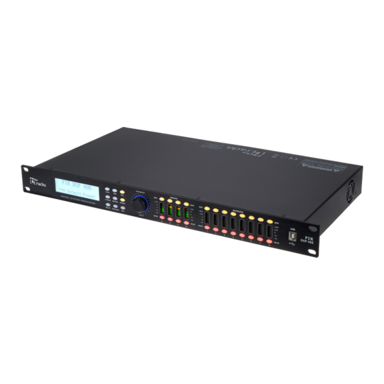
- Page 1 FIR DSP 408 Controller...
- Page 2 Thomann GmbH Hans-Thomann-Straße 1 96138 Burgebrach Germany Telephone: +49 (0) 9546 9223-0 Internet: www.thomann.de 04.12.2023, ID: 472928 (V2)
-
Page 3: Table Of Contents
Safety instructions......................... 6 Features............................7 Installation and starting up....................8 Connections and controls....................10 Operating on the unit......................12 Operating on the computer.................... 17 Technical specifications....................27 Plug and connection assignment................. 28 Protecting the environment................... 29 FIR DSP 408 Controller... - Page 4 FIR DSP 408 Controller...
-
Page 5: General Information
This combination of symbol and signal word indicates a possible dangerous situation that can result in mate‐ rial and environmental damage if it is not avoided. Warning signs Type of danger Warning – high-voltage. Warning – danger zone. FIR DSP 408 Controller... -
Page 6: Safety Instructions
Using fuses of a different type than compatible with the device may cause a fire and seriously damage the device. Only use fuses of the same type. Observe the labelling on the device casing and the information in the "Technical data” chapter. FIR DSP 408 Controller... -
Page 7: Features
D-sub connector (RS232 / 485) for remote control of the device or cascading of several devices Ethernet interface (RJ45) for integration of the device into a local network Operation on the device via buttons, rotary switch and display FIR DSP 408 Controller... -
Page 8: Installation And Starting Up
The unit has been designed for rack mounting in a standard 19-inch rack; it occupies one rack unit. Configuration example 1 The figure schematically shows how the device can be controlled via a computer's USB port. USB Cable Computer FIR DSP 408 Controller... - Page 9 The illustrations show schematically how one device or several devices can be inte‐ grated into a local area network (LAN). Computer WIFI Router Computer ID 1 ID 2 Configuration example 3 The illustrations show schematically how a device can be configured via the serial port. Computer ID 1 FIR DSP 408 Controller...
-
Page 10: Connections And Controls
LEDs indicate that the built-in limiter has responded. 8 [USB] | USB interface 9 [MUTE] | Buttons for muting or unmuting the respective output channel 10 [MUTE] | Buttons for muting or unmuting the respective input channel FIR DSP 408 Controller... - Page 11 15 [OUTPUTS] | XLR panel plugs for the output channels. The number of channels depends on the device version. 16 [INPUTS] | XLR panel sockets for the input channels. The number of channels depends on the device version. FIR DSP 408 Controller...
-
Page 12: Operating On The Unit
The test tone generator optionally generates: Pink noise, white noise or a sine wave 20 Hz… 20 kHz. ‘Copy CH select’ Transferring settings from one channel to another. ‘LCD DISPLAY TIME’ Setting the backlight duration: Max. 200 ms FIR DSP 408 Controller... - Page 13 Use the rotary switch to select a user preset between ‘U01’ and ‘U20’ . Press the rotary switch to confirm. Use the rotary switch to enter the name of the user preset by changing the default value Default Preset. ð The settings are being saved. Press [EXIT]. FIR DSP 408 Controller...
- Page 14 ‘COMPRESSO [DYNAMIC] ‘T’ : ‘–60dB’ … ‘+20dB’ Compressor parameters: Threshold, ratio, soft R’ knee, attack, release ‘R’ : ‘1:1’ … ‘1:10’ ‘K’ : ‘0dB’ … ‘12dB’ ‘A’ : ‘10ms’ … ‘900ms’ ‘R’ : ‘10ms’ … ‘3000ms’ FIR DSP 408 Controller...
- Page 15 ‘HCUT’ , ‘A-PAS1’ , ‘A-PAS2’ and ‘BP’ ‘MATRIX’ [MATRIX] Assignment selection of input channels to the respective output channel. To each output channel, an input channel or the mix of several input channels can be freely assigned. FIR DSP 408 Controller...
- Page 16 2 × ‘T’ : ‘–60dB’ … ‘+20dB’ Limiter parameters: Threshold, ratio, soft knee, [DYNAMIC] attack, release. ‘R’ : ‘1:1’ … ‘1:10’ ‘K’ : ‘0dB’ … ‘12dB’ ‘AT’ : ‘10ms’ … ‘999ms’ ‘REL’ : ‘10ms’ … ‘3000ms’ FIR DSP 408 Controller...
-
Page 17: Operating On The Computer
All tabs of the programme window have a similar structure and are divided into the window following areas: ö & Tab for selecting a function group Main menu Button for the status of the connection to the PC Display area Control area Buttons for quick access to important presets FIR DSP 408 Controller... - Page 18 Meaning Address Display of the device identification in a series connection and the IP address for integration into a local network Preset Display of the current user's preset Store Saving user preset Recall Recalling user preset FIR DSP 408 Controller...
- Page 19 Drag the faders with the mouse to adjust the levels for the input and output channels. The ‘Mute’ button mutes or unmutes the respective channel. The ‘Normal’ / ‘Inverse’ button inverts the phase of the respective channel by 180° when needed. FIR DSP 408 Controller...
- Page 20 The red dot in the curve corresponds to the current signal. Control area Drag the faders with the mouse to set the noise gate parameters for all input and output channels: Threshold, hold, attack, release. FIR DSP 408 Controller...
- Page 21 Shows the current settings of the limiter for the respective channel, with a symbolic level indicator appearing next to it for all channels. Control area Drag the faders with the mouse to set the limiter parameters for all input and output channels: Threshold, attack, ratio, soft knee, release. FIR DSP 408 Controller...
- Page 22 Shows the set delays for all in and output channels. Control area Drag the faders with the mouse to adjust the delay for the respective channel. Press one of the but‐ tons ‘ms’ , ‘m’ or ‘ft’ to select the unit to be used. FIR DSP 408 Controller...
- Page 23 The green input channels are assigned to the respective output channel. You can adjust the level for each combina‐ tion of input and output channel. FIR DSP 408 Controller...
- Page 24 Drag the fader in the right part of the window using the mouse to set the level for the input channel. The ‘Mute’ button mutes or unmutes the respective channel. The ‘Normal’ / ‘Inverse’ button inverts the phase of the respective channel by 180° when needed. FIR DSP 408 Controller...
- Page 25 Operating on the computer ‘Out’ tab FIR DSP 408 Controller...
- Page 26 Drag the fader in the right part of the window using the mouse to set the level for the output channel. The ‘Mute’ button mutes or unmutes the respective channel. The ‘Normal’ / ‘Inverse’ button inverts the phase of the respective channel by 180° when needed. FIR DSP 408 Controller...
-
Page 27: Technical Specifications
Dimensions (W × H × D) 482 mm × 44 mm (1 RU) × 247 mm Weight 2.7 kg Ambient conditions Temperature range 0 °C…40 °C Relative humidity 20%…80% (non-condensing) Further information Channels Number of frequency bands Tube FIR DSP 408 Controller... -
Page 28: Plug And Connection Assignment
Even if a plug fits into the socket, an incorrect connection may result in a destroyed power amp, a short circuit or ‘just’ in poor transmission quality! XLR plug (balanced) Ground, shielding Signal (in phase, +) Signal (out of phase, –) Shielding on plug housing (option) FIR DSP 408 Controller... -
Page 29: Protecting The Environment
Dispose of this device through an approved waste disposal firm or through your local waste facility. When discarding the device, comply with the rules and regulations that apply in your country. If in doubt, consult your local waste disposal facility. FIR DSP 408 Controller... - Page 30 Notes FIR DSP 408 Controller...
- Page 32 Musikhaus Thomann · Hans-Thomann-Straße 1 · 96138 Burgebrach · Germany · www.thomann.de...
Need help?
Do you have a question about the FIR DSP 408 and is the answer not in the manual?
Questions and answers