Advertisement
Table of Contents
Advertisement
Table of Contents

Related Manuals for The t.racks DSP 204

Summary of Contents for The t.racks DSP 204
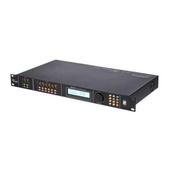
- Page 1 DSP 204, DSP 206, DSP 306, DSP 408 Digital speaker management system user manual...
- Page 2 Musikhaus Thomann Thomann GmbH Hans-Thomann-Straße 1 96138 Burgebrach Germany Telephone: +49 (0) 9546 9223-0 E-mail: info@thomann.de Internet: www.thomann.de 14.06.2018, ID: 435191, 435192, 435193, 435194...
-
Page 3: Table Of Contents
Features............................7 Installation and starting up....................8 Connections and controls....................10 Operating on the unit......................12 Control on the computer....................18 Technical specifications....................29 Plug and connection assignment................. 30 Protecting the environment................... 31 DSP 204, DSP 206, DSP 306, DSP 408... -
Page 4: General Information
General information General information This manual contains important instructions for the safe operation of the unit. Read and follow the safety instructions and all other instructions. Keep the manual for future reference. Make sure that it is available to all those using the device. If you sell the unit please make sure that the buyer also receives this manual. -
Page 5: Symbols And Signal Words
This combination of symbol and signal word indicates a possible dangerous situation that can result in mate- rial and environmental damage if it is not avoided. Warning signs Type of danger Warning – danger zone. DSP 204, DSP 206, DSP 306, DSP 408... -
Page 6: Safety Instructions
Safety instructions Safety instructions Intended use This device is intended to be used for amplification, mixing and playback of signals from musical instruments and microphones. Use the device only as described in this user manual. Any other use or use under other operating conditions is considered to be improper and may result in personal injury or property damage. -
Page 7: Features
Features Features Digital mixer Inputs: – DSP 204 (item no. 435191): 2 mono channels (XLR chassis sockets) for signals with line level – DSP 206 (item no. 435192): 2 mono channels (XLR chassis sockets) for signals with line level –... -
Page 8: Installation And Starting Up
Installation and starting up Installation and starting up Unpack and carefully check that there is no transportation damage before using the unit. Keep the equipment packaging. To fully protect the device against vibration, dust and moisture during transportation or storage use the original packaging or your own packaging material suitable for transport or storage, respectively. - Page 9 The figure schematically shows how one or more devices can be integrated into a local network (LAN). Configuration example 3 The figure schematically shows how one or more devices can be connected in a row via the serial interface (cascading). DSP 204, DSP 206, DSP 306, DSP 408...
-
Page 10: Connections And Controls
Connections and controls Connections and controls Front panel 1 [INPUTS] Level indicator for the input channels. The number of channels depends on the device design. The red [CLIP] LEDs indicate overload (clipping). In this case the level of the input signal is too high. 2 [EDIT] Buttons for selecting the edit mode for the respective input channel. - Page 11 XLR chassis plugs for the output channels. The number of channels depends on the device design. 16 [INPUTS] XLR chassis sockets for the output channels. The number of channels depends on the device design. DSP 204, DSP 206, DSP 306, DSP 408...
-
Page 12: Operating On The Unit
Operating on the unit Operating on the unit Starting the device Connect the device to the power grid and turn it on with the main switch to start operation. After a few seconds, the display indicates that a reset is in progress. The device is then ready for use. - Page 13 ð The ‘Load preset’ menu opens. Use the jog wheel to select a user preset between ‘U01’ and ‘U20’ or the basic setting ‘F00’ . Press the jog wheel to confirm. ð The settings are loaded. DSP 204, DSP 206, DSP 306, DSP 408...
- Page 14 Operating on the unit Input settings Press the [EDIT] button assigned to the desired channel. ð The settings menu for the desired channel will open. The display shows ‘GAIN’ . In the basic state of the menu, you can set the level of the channel within a range of –60 dB…+12 dB using the jog wheel.
- Page 15 Parameters for the noise gate: Threshold, hold, GATE] attack, release ‘HT’ : ‘10’ … ‘999’ (in milliseconds) ‘AT’ : ‘1ms’ … ‘999ms’ ‘RT’ : ‘10ms’ … ‘3000ms’ ‘PHASE’ [PHASE] ‘0’ , ‘180’ Inversion of phase length DSP 204, DSP 206, DSP 306, DSP 408...
- Page 16 Operating on the unit Output settings Press the [EDIT] button assigned to the desired channel. ð The settings menu for the desired channel will open. The display shows ‘GAIN’ . In the basic state of the menu, you can set the level of the channel within a range of –60 dB…+12 dB using the jog wheel.
- Page 17 ‘TH’ : ‘-90dB’ … ‘+20dB’ Parameters for the limiter: Threshold, attack, [COMP/ release ‘AT’ : ‘1ms’ … ‘999ms’ GATE] ‘RT’ : ‘10ms’ … ‘3000ms’ ‘PHASE’ [PHASE] ‘0’ , ‘180’ Inversion of phase length DSP 204, DSP 206, DSP 306, DSP 408...
-
Page 18: Control On The Computer
Control on the computer Control on the computer Installing and starting the software Place the CD with the software into the CD drive of a computer with a Win- dows operating system and start the installation programme that matches the device you have. - Page 19 Rename the input and output channels ‘Language’ Language selection for the programme user interface (English or Chinese) ‘Help’ Display of the control code for the serial interface ‘About’ Information about the programme version DSP 204, DSP 206, DSP 306, DSP 408...
- Page 20 Control on the computer Buttons for quick access to the impor- tant presets Range Meaning Address Display of the ID of the device in a serial configuration or IP address for integrating into a local net- work Preset Display of the current user preset Store Save user preset Recall...
- Page 21 The red dot on the curve represents the cur- rent signal. Control area Drag the fader with the mouse to set the noise gate parameters for all input and output channels: Threshold, hold, attack, release DSP 204, DSP 206, DSP 306, DSP 408...
- Page 22 Control on the computer “Comp” tab Range Meaning Display area Shows the current settings of the compressor function for the respective output channel, with a sym- bolic level indicator symbol appearing next to it for the input channels. The red dot on the curve rep- resents the current signal.
- Page 23 Shows the current settings of the limiter for the respective channel, with a symbolic level indicator symbol appearing next to it for all channels. Control area Drag the fader with the mouse to set the limiter parameters for all input and output channels: Threshold, attack, release DSP 204, DSP 206, DSP 306, DSP 408...
- Page 24 Control on the computer “Delay” tab Range Meaning Display area Shows the set delays for all input and output channels. Control area Drag the fader with the mouse to set the delay for the respective channel. Press one of the buttons ‘ms’...
- Page 25 The input channels with a green background are assigned to the respective output channel. You can set a level adjustment for any combination of input and output channel. DSP 204, DSP 206, DSP 306, DSP 408...
- Page 26 Control on the computer “GEQ” tab Range Meaning Display area Shows the setting of the graphic equalizer for the selected input channel. Click on the ‘EQ Bypass’ button to temporarily switch off the equalizer function for this channel or on the ‘EQ Reset’ button to return the equalizer to its basic status.
- Page 27 Drag the fader into the right part of the window using the mouse to set the level for the input channel. The ‘Mute’ button mutes or unmutes the respective channel. The ‘Normal’ / ‘Inverse’ button shifts the phase of the respective channel by 180° if needed. DSP 204, DSP 206, DSP 306, DSP 408...
- Page 28 Control on the computer “Out” tab Range Meaning Display area Use the option fields ‘Mag’ and ‘PHASE’ to switch the diagram from Cartesian coordinates (level vs. frequency) to polar coordinates (angle vs. frequency). Use the option field ‘SHOW ALL EQ’ to show the parameters for all nine of the frequency bands. Control area You can enter the parameters of the parametric equalizer for each input channel and all nine fre- quency bands (numbered with ‘PEQ’...
-
Page 29: Technical Specifications
Power consumption 20 W Fuse 5 mm × 20 mm, 2 A, 250 V, slow-blow Dimensions (W × H × D) 480 × 45 × 24.5 mm Weight 2.62 kg Block diagram DSP 204, DSP 206, DSP 306, DSP 408... -
Page 30: Plug And Connection Assignment
Plug and connection assignment Plug and connection assignment Introduction This chapter will help you select the right cables and plugs to connect your valuable equipment in such a way that a perfect sound experience is ensured. Please note these advices, because especially in ‘Sound & Light’ caution is indicated: Even if a plug fits into the socket, an incorrect connection may result in a destroyed power amp, a short circuit or ‘just’... -
Page 31: Protecting The Environment
Dispose of this device through an approved waste disposal firm or through your local waste facility. When discarding the device, comply with the rules and regulations that apply in your country. If in doubt, consult your local waste disposal facility. DSP 204, DSP 206, DSP 306, DSP 408... - Page 32 Notes Digital speaker management system...
- Page 33 Notes DSP 204, DSP 206, DSP 306, DSP 408...
- Page 34 Notes Digital speaker management system...
- Page 36 Musikhaus Thomann · Hans-Thomann-Straße 1 · 96138 Burgebrach · Germany · www.thomann.de...
Need help?
Do you have a question about the DSP 204 and is the answer not in the manual?
Questions and answers