DeWalt DW682, DW682KR - Plate Joiner Manual
- Original instructions manual (109 pages) ,
- Instruction manual (50 pages) ,
- Manual (19 pages)
Advertisement
General Safety Instructions


Read and understand all instructions. Failure to follow all instructions listed below may result in electric shock, fire and/or serious personal injury.
SAVE THESE INSTRUCTIONS
WORK AREA
- Keep your work area clean and well lit. Cluttered benches and dark areas invite accidents.
- Do not operate power tools in explosive atmospheres, such as in the presence of flammable liquids, gases, or dust. Power tools create sparks which may ignite the dust or fumes.
- Keep bystanders, children, and visitors away while operating a power tool. Distractions can cause you to lose control.
ELECTRICAL SAFETY
- Grounded tools must be plugged into an outlet properly installed and grounded in accordance with all codes and ordinances. Never remove the grounding prong or modify the plug in any way. Do not use any adaptor plugs. Check with a qualified electrician if you are in doubt as to whether the outlet is properly grounded. If the tools should electrically malfunction or break down, grounding provides a low resistance path to carry electricity away from the user. Applicable only to Class I (grounded) tools.
- Double insulated tools are equipped with a polarized plug (one blade is wider than the other.) This plug will fit in a polarized outlet only one way. If the plug does not fit fully in the outlet, reverse the plug. If it still does not fit, contact a qualified electrician to install a polarized outlet. Do not change the plug in any way. Double insulation eliminates the need for the three wire grounded power cord and grounded power supply system. Applicable only to Class II (double insulated) tools.
![shock hazard]() Avoid body contact with grounded surfaces such as pipes, radiators, ranges and refrigerators. There is an increased risk of electric shock if your body is grounded.
Avoid body contact with grounded surfaces such as pipes, radiators, ranges and refrigerators. There is an increased risk of electric shock if your body is grounded.![shock hazard]() Don't expose power tools to rain or wet conditions. Water entering a power tool will increase the risk of electric shock.
Don't expose power tools to rain or wet conditions. Water entering a power tool will increase the risk of electric shock.![shock hazard]() Do not abuse the cord. Never use the cord to carry the tools or pull the plug from an outlet. Keep cord away from heat, oil, sharp edges or moving parts. Replace damaged cords immediately.Damaged cords increase the risk of electric shock.
Do not abuse the cord. Never use the cord to carry the tools or pull the plug from an outlet. Keep cord away from heat, oil, sharp edges or moving parts. Replace damaged cords immediately.Damaged cords increase the risk of electric shock.![shock hazard]() When operating a power tool outside, use an outdoor extension cord marked "W-A" or "W." These cords are rated for outdoor use and reduce the risk of electric shock. When using an extension cord, be sure to use one heavy enough to carry the current your product will draw. An undersized cord will cause a drop in line voltage resulting in loss of power and overheating. The following table shows the correct size to use depending on cord length and nameplate ampere rating. If in doubt, use the next heavier gage. The smaller the gage number, the heavier the cord.
When operating a power tool outside, use an outdoor extension cord marked "W-A" or "W." These cords are rated for outdoor use and reduce the risk of electric shock. When using an extension cord, be sure to use one heavy enough to carry the current your product will draw. An undersized cord will cause a drop in line voltage resulting in loss of power and overheating. The following table shows the correct size to use depending on cord length and nameplate ampere rating. If in doubt, use the next heavier gage. The smaller the gage number, the heavier the cord.
 Avoid body contact with grounded surfaces such as pipes, radiators, ranges and refrigerators. There is an increased risk of electric shock if your body is grounded.
| Minimum Gage for Cord Sets | |||||
| Volts | Total Length of Cord in Feet | ||||
| 120V | 0-25 | 26-50 | 51-100 | 101-150 | |
| 240V | 0-50 | 51-100 | 101-200 | 201-300 | |
| Ampere Rating | |||||
| More | Not more | AWG | |||
| Than | Than | ||||
| 6 | -10 | 18 | 16 | 14 | 12 |
PERSONAL SAFETY
- Stay alert, watch what you are doing and use common sense when operating a power tool. Do not use tool while tired or under the influence of drugs, alcohol, or medication.Amoment of inattention while operating power tools may result in serious personal injury.
- Dress properly. Do not wear loose clothing or jewelry. Contain long hair. Keep your hair, clothing, and gloves away from moving parts.Loose clothing, jewelry, or long hair can be caught in moving parts. Air vents often cover moving parts and should also be avoided.
- Avoid accidental starting. Be sure switch is off before plugging in. Carrying tools with your finger on the switch or plugging in tools that have the switch on invites accidents.
- Remove adjusting keys or wrenches before turning the tool on.Awrench or a key that is left attached to a rotating part of the tool may result in personal injury.
- Do not overreach. Keep proper footing and balance at all times.Proper footing and balance enables better control of the tool in unexpected situations.
- Use safety equipment. Always wear eye protection.Dust mask, non-skid safety shoes, hard hat, or hearing protection must be used for appropriate conditions.
TOOL USE AND CARE
- Use clamps or other practical way to secure and support the workpiece to a stable platform.Holding the work by hand or against your body is unstable and may lead to loss of control.
- Do not force tool. Use the correct tool for your application. The correct tool will do the job better and safer at the rate for which it is designed.
- Do not use tool if switch does not turn it on or off. Any tool that cannot be controlled with the switch is dangerous and must be repaired.
- Disconnect the plug from the power source before making any adjustments, changing accessories, or storing the tool.Such preventative safety measures reduce the risk of starting the tool accidentally.
- Store idle tools out of reach of children and other untrained persons. Tools are dangerous in the hands of untrained users.
- Maintain tools with care. Keep cutting tools sharp and clean. Properly maintained tools, with sharp cutting edges are less likely to bind and are easier to control.
- Check for misalignment or binding of moving parts, breakage of parts, and any other condition that may affect the tool's operation. If damaged, have the tool serviced before using. Many accidents are caused by poorly maintained tools.
- Use only accessories that are recommended by the manufacturer for your model. Accessories that may be suitable for one tool, may become hazardous when used on another tool.
SERVICE
- Tool service must be performed only by qualified repair personnel.Service or maintenance performed by unqualified personnel could result in a risk of injury.
![shock hazard]() When servicing a tool, use only identical replacement parts. Follow instructions in the Maintenance section of this manual. Use of unauthorized parts or failure to follow maintenance instructions may create a risk of electric shock or injury.
When servicing a tool, use only identical replacement parts. Follow instructions in the Maintenance section of this manual. Use of unauthorized parts or failure to follow maintenance instructions may create a risk of electric shock or injury.
Additional Specific Safety Instructions
![shock hazard]() Hold tool by insulated gripping surfaces when performing an operation where the cutting tool may contact hidden wiring or its own cord. Contact with a "live" wire will make exposed metal parts of the tool "live" and shock the operator.
Hold tool by insulated gripping surfaces when performing an operation where the cutting tool may contact hidden wiring or its own cord. Contact with a "live" wire will make exposed metal parts of the tool "live" and shock the operator.

Wear appropriate hearing protection during use. Under some conditions and duration of use, noise from this product may contribute to hearing loss.

Some dust created by power sanding, sawing, grinding, drilling, and other construction activities contains chemicals known to cause cancer, birth defects or other reproductive harm. Some examples of these chemicals are:
- lead from lead-based paints,
- crystalline silica from bricks and cement and other masonry products, and
- arsenic and chromium from chemically-treated lumber (CCA).
Your risk from these exposures varies, depending on how often you do this type of work. To reduce your exposure to these chemicals: work in a well ventilated area, and work with approved safety equipment, such as those dust masks that are specially designed to filter out microscopic particles.
- Avoid prolonged contact with dust from power sanding, sawing, grinding, drilling, and other construction activities. Wear protective clothing and wash exposed areas with soap and water.Allowing dust to get into your mouth, eyes, or lay on the skin may promote absorption of harmful chemicals.
Use of this tool can generate and/or disburse dust, which may cause serious and permanent respiratory or other injury. Always use NIOSH/OSHA approved respiratory protection appropriate for the dust exposure. Direct particles away from face and body.
- The label on your tool may include the following symbols. The symbols and their defini-tions are as follows:
| V | volts | A | amperes |
| Hz | hertz | W | watts |
| min | minutes |  | alternating current |
 | direct current | n0 | no load speed |
 | Class II Construction |  | earthing terminal |
 | safety alert symbol | .../min | revolutions per minute |
SAVE THESE INSTRUCTIONS
Introduction
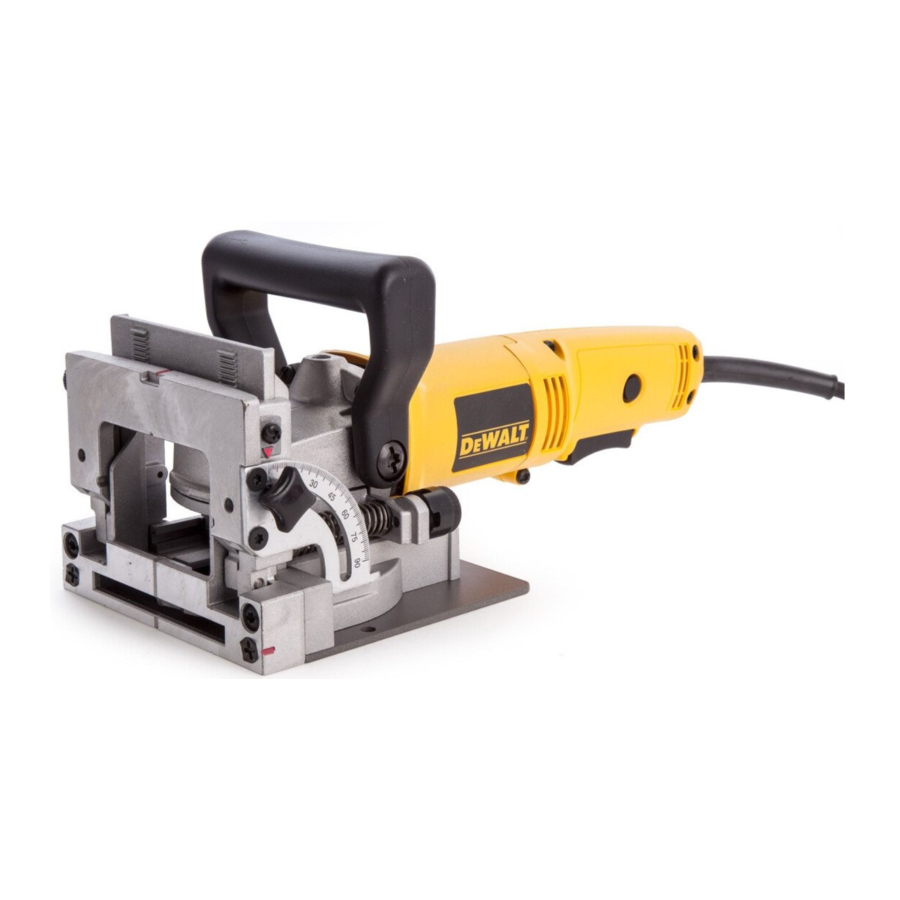
Examine Figure 1 and your plate joiner for a few minutes to become familiar with the various features and the names used to describe them. The following sections will discuss the various controls and you will need to know where they are.

Overview
You have purchased a precision woodworking tool. The function of the plate joiner is to enable you to make extremely strong and accurate joints in wood and wood by products.
The tool works by a plunging action to precisely cut crescent shaped slots for the placement of flat wooden dowels or "biscuits" like those shown in Figure 2.

The various adjustments on the patented base/fence assembly will enable you to make virtually any biscuit joint imaginable. The tool may be further enhanced by some simple jigs and fixtures that can be easily made. Some of the more common biscuit joinery applications are shown in Figure 3 and are discussed in detail in the applications section of this manual.

Switch
Your plate joiner has a trigger switch located on the underside, as shown in Figure 1. To turn the tool on, depress the trigger. To turn the tool off, release the trigger. To lock the tool on for continuous operation, there is a lock on button located at the rear of the tool just above the cord. When cutting always hold the tool with one hand on the switch handle and one hand on the auxiliary handle. To lock the tool on, depress and hold the trigger as you depress the lock button. Hold the lock button in as you gently release the trigger. The tool will continue to run. To turn the tool off from a locked on condition, depress and release the trigger once.
Blade Replacement
In time your saw blade will wear out and need replacement. To remove the blade, follow the steps below.
- Turn off and unplug the plate joiner.
- Remove the 4 torx head screws from the bottom of the shoe, using the T20 torx screwdriver provided.
- Rotate the shoe out of the way.
- Use the spanner wrench provided to loosen (counterclockwise) the blade nut. Depress thespindle lock pin on the top of the gear case to hold the spindle while you unscrew the nut.
- Remove the blade and have it sharpened or replace it with a new one.
- Reinstall the blade by reversing the steps above. Be sure blade teeth point counterclockwise as shown in Figure 4.
![]()
- Always check the fine depth adjustment when sharpening or replacing the blade. Adjust if necessary. (See "Controls" section).

The Controls
The heart of your plate joiner is the base/fence assembly. All of the controls that let you make a variety of precision cuts are located on this assembly. Take a few minutes to become familiar with the various controls.
ALWAYS TURN OFF AND UNPLUG PLATE JOINER BEFORE MAKING ANYADJUSTMENTS.
- ADJUSTABLE FENCE
The adjustable fence provides a sturdy, precise reference surface to determine the point at which the slots for the biscuits will be cut. Its adjustable height feature allows you to position biscuit slots as close as 3/16" (4.76mm) and as distant as 1-3/8" (35mm) measured from the workpiece surface to the centerline of the blade (see Figure 6). The adjustable angle feature allows a full range of settings from 0° to 90 as well as a reverse 45° bevel which allows outside registration on miter joints. (See Applications section under Miter Joints, Figure 26.)
The height adjustment is accomplished by first loosening the lock knob on the right side of the fence and then rotating the knurled adjustment knob until the desired height is reached (see Figure 5).
Tightening the lock knob will then automatically align the fence parallel to the blade and lock it in position. The vertical scale and pointer located directly under the lock knob can be used to assist in setting this height. The scale readings indicate distance from the blade centerline to the fence surface when the fence is set at 90° (see Figure 6). The fence angle can be set simply by loosening the lock knob on the left side of the tool, aligning the protractor scale with the pointer and tightening the lock knob.

- PLUNGE DEPTH ADJUSTMENT
The depth of cut can be set to match the dimensions of the particular size biscuit you will be using. The numbers on the depth adjustment knob (0,10,20,M) coincide with the three sizes of biscuits shown in Figure 2. The letter M stands for the maximum depth capacity of the tool which is 20mm (25/32"). This depth is obtainable only with a new blade and by backing out the fine adjustment screw (see next section).
NOTE: The M setting has been provided for future use and will not be necessary for most biscuiting operations. To select a depth, align the appropriate number with the red mark scribed in the tool's housing, as shown in Figure 7. Rotate the depth adjustment knob to the desired position and it will "click" into place.

- FINE DEPTH ADJUSTMENT
You may encounter situations where you want to leave a little looseness in your joint so that you can move it slightly before the glue sets up. For these instances a fine depth adjustment has been provided. To adjust, you must first raise the adjustable fence to its uppermost position. Then insert the T20 torx wrench provided into the opening as shown in Figure 8. Turn the depth adjustment screw clockwise for less depth and counterclockwise for increased depth. Each full turn causes a change in depth of 1mm (0.04"). Always check the depth adjustment by first making test cuts in scrap wood.

- ANTI-SLIPPAGE PINS
Plate Joiners tend to slide to the right with respect to the workpiece when making a cut. This tendency is increased with a dull blade or when plunging very rapidly. Anti-slippage pins have been provided to reduce this tendency and are located on the front registration surface on either side of the blade opening slot. When making some joints, you may wish to retract the anti-slippage pins so as not to scratch your workpiece in a visible area. For this purpose, simply rotate the anti-slippage pins approximately 1/6 of a turn and they will retract back behind the front registration surface. A flat blade screwdriver can be used to rotate the pins as shown in Figure 9.
![]()
- BOTTOM REGISTRATION SURFACE
For certain applications, you will want to use the bottom surface of the plate joiner for alignment. When using the bottom registration surface, the adjustable fence should be set to 0° and the height setting is unimportant. This surface is used primarily when making 'T' joints (see applications section). The distance between the centerline of the blade and the bottom registration surface is fixed at 3/8" (9.5mm) which allows centering on 3/4" (19mm) thick stock. The 3 red marks on the bottom registration surface indicate the centerline (or the deepest point) of the biscuit cut and the approximate width of a #20 biscuit so that you'll know where the edge of the blade is and can prevent breakthrough. To avoid breaking through the workpiece, align the shoe so that neither outside mark extends beyond the end of the workpiece. If either side does, there is a good chance that the blade will break through the surface and ruin your work. - DUST EXTRACTION
There are three options provided for collecting dust from your plate joiner as described below.- Adjustable Direction Elbow (See Figure 10)
This attachment inserts into the dust exhaust port on the right side at the rear of the base assembly and clicks into place. To remove, pull out firmly. The directional elbow rotates easily to aim the dust in the most convenient direction suitable for the particular application.

- Dust Adaptor (See Figure 11)
This attachment, when inserted as described above, allows the use of several common sizes of vacuum hose to be attached for direct vacuum pick-up of the dust.

- Dust Bag (See Figure 12)
The dust bag provided fits snugly over the dust adaptor described above. To empty the bag, open the zipper underneath and dump dust out.
NOTE: When the bag becomes full, the dust will back-up into the adaptor and the exhaust port on the right rear of the tool. To clean out, turn off and unplug the tool and remove packed dust. The bag will hold the dust generated from approximately 70 to 100 #20 biscuit cuts before filling up.
![]()
- Adjustable Direction Elbow (See Figure 10)


General Operation
Plate joiners are primarily used for making cabinetry and furniture, joining millwork or other similar applications where a strong, accurate joint is required in wood or wood by-products. There are literally hundreds of variations of joints that can be made with your Plate Joiner. We will limit our discussion to six basic joints that can be used to build on and adapt to your own applications. The following are some basic set-up steps that will apply to all biscuit joints.
BISCUIT SIZE SELECTION
As mentioned earlier, the three biscuit sizes are #0, #10 and #20. It is a good rule of thumb to use the largest biscuit size that will physically fit in the application. Unless you are joining narrow face or picture frames or using 1/2" or thinner stock, you will find the #20 biscuit size to suit most applications. After selecting the biscuit size, set the depth adjustment knob to the corresponding size (see Controls section). Also, be sure the fine depth adjustment is correctly set by first testing in a scrap piece. This is extremely important as you do not want to discover during glue-up that your biscuit slots are not quite deep enough.
BISCUIT LOCATION AND LAYOUT
Generally, biscuits may be spaced and located at your discretion. For edge joints, a good rule of thumb is to space biscuits every 6-10 inches on center. It is further recommended that biscuits be placed so that the centerline of the end biscuits is 2-3 inches from the end of the workpiece. When joining face frames or picture frames where the workpiece is narrow, you may have to choose the smaller biscuit sizes to keep from "breaking out" on the end of the joint. Breaking out should be avoided if possible, but if not you can assemble the joint and trim off the exposed biscuit tip after the glue sets (see Figure 13). When working with material up to 1" thick, we advise to use a single biscuit located in the approximate center of the material thickness. If thicker stock is to be joined, you may choose to use 2 biscuits across the thickness for greater strength (see Figure 14). Biscuit locations should be marked by first positioning the mating pieces exactly as they are to be assembled. Next, make a mark at 90° to the joint interface across both pieces at the desired biscuit locations (see Figure 15). See Application section for more specific information on joint layout. The marks you make will then be aligned with one of the center registration marks on the tool, again, depending upon your specific application.


MAKING THE CUT
Prior to making any cut, be sure that all fence adjustments are set and lock knobs are tight. Also, be sure you have selected the proper depth setting. Clamp your workpiece firmly and align the plate joiner's center registration mark with your layout mark. Turn on the tool and let the blade come up to full speed (approximately 1 second). Grasping the switch handle and auxiliary handle and positioning the fence firmly and squarely against the workpiece, plunge the blade until it bottoms against the stop. Continuing to hold the tool squarely and firmly, allow the return spring to retract the blade from the work and then release the switch to shut the tool off. It will take some practice to obtain a "feel" for the tool to produce accurate joints, so practicing in scrap wood first is advisable.
JOINT ASSEMBLY
After your joints are cut, you may wish to trial fit everything together before gluing. When you are satisfied with your joints, evenly spread any good quality woodworking glue in each slot as well as on the mating flat surfaces of your joint. Place biscuits in the slots, assemble the joint and clamp until dry. For a biscuit joint to be most effective, it is important that the biscuits themselves be in contact with the glue. This is because the biscuits absorb the moisture in the glue and expand to form a tight joint.
Applications
EDGE TO EDGE JOINTS
(See Figure 16)
This is the simplest to make and most common joint for the plate joiner. Follow the steps below to produce this joint.

- Prepare the workpieces and lay them on a work surface exactly as they are to beassembled.
- Spacing biscuits 2-3" in from the ends and 6-10" apart, layout the biscuit centers.
- Set up the plate joiner by first selecting the proper depth setting. Set the fence to 90°.Set the height adjustment to position the biscuit in the approximate center of the stock thickness.
- Clamp the workpiece and position the tool so that the center indicator mark lines upwith the first layout mark (see Figure 17). Turn on the tool and make the plunge cut. Retract the tool and release the trigger to turn the tool off. Repeat for each layout mark.
![]()
- Glue, assemble and clamp the joint.
- For stock thicker than 1", you may wish to use double biscuits at each location. Set the height adjustment to allow at least 3/16" of stock between the biscuit and the edge of the work surface. Make all cuts at this fence setting before readjusting the fence for the lower cuts. Again, there should be at least 3/16" of stock between the biscuit and the outside wall and between the biscuits themselves (see Figure 18).


FRAME JOINTS
(See Figure 19)
Frame joints are an ideal application for biscuit joinery. With the plate joiner you can create a very strong, precise joint that is much faster to make than a dowel or mortise and tenon joint. Figure 19 shows two types of frame joints. Follow the steps outlined below.

- Arrange the workpieces on a flat work surface exactly as they are to be assembled.
- Select the proper biscuit size based on the length of the joint. (If the frame pieces are too narrow for a #0 biscuit, you will have to allow the biscuit tip to protrude slightly and then trim it off after the joint is dry (see Figure 13).
- Lay out the biscuit locations.
- Set up the tool by selecting the depth that corresponds to the chosen biscuit size. Lockthe fence at 90° and adjust the fence height to center the biscuit on the stock thickness.
- Clamp the workpiece and position the Plate Joiner to make the first cut (see Figure 20).
![]()
- Turn on the tool and make the plunge cut.
- Repeat for each layout mark.
- Glue, assemble and clamp the frame.

CORNER JOINTS
(See Figure 21)
Corner joints are another common and excellent application for biscuit joinery. Follow the procedure below.

- Arrange the workpieces exactly as they are to be joined.
- Select the biscuit size and layout the biscuit locations.
- Set up the tool by selecting the proper depth setting, adjusting the fence to center onthe stock thickness and setting the angle to 90°.
- For this joint, you will make cuts into the edge of one workpiece and the face of anoth-er. The edge cut is performed the same as for edge to edge joints. The face cut is made by clamping the workpiece and aligning the tool as shown in Figure 22. Turn the tool on, make the plunge cut and repeat for each layout mark.
![]()
- Glue, assemble and clamp the joint.

OFFSET JOINTS
(See Figure 23)
You may wish to have a deliberate offset between two workpieces. This is easily accomplished with your plate joiner by performing the following steps.

- Arrange the workpieces as they are to be assembled and layout the biscuit locations.
- Set up the tool by selecting the proper biscuit size and adjusting the fence angle to 90°.Select the workpiece that will be set back and adjust the fence height to center the cut within the thickness of that piece.
- Clamp the workpiece, align the tool and make the plunge cut.
- Next, adjust the fence up by an amount equal to the desired offset. Use the scale andpointer located on the right side of the tool under the fence lock knob.
- Clamp the second workpiece, align the tool and make the plunge cut.
- Glue, assemble and clamp the joint.
EDGE MITER JOINTS
(See Figure 24)
Edge miters are most commonly used in box structures or for making multisided pedestals where you would like to hide the end grain. Once again, biscuit joinery is an outstanding method to use both for added strength as well as ease of assembly. Follow the steps below to assemble a 90° joint.

- Position the workpieces as they are to be assembled and layout biscuit locations onthe outside of the joint.
- Set up tool by first setting fence angle to 90°. Make the fence adjustment such that the biscuit is located toward the inside of the joint where the material is thicker, then select the biscuit size so that the blade does not protrude through the outside wall when the cut is made (see Figure 25).
![]()
- Clamp the workpiece and align the tool as shown in column in Figure 26.

- Turn on the tool and make the plunge cut.
- Glue, assemble and clamp the joint.
- For joints other than 90° see outside registration column Figure 27 for proper fence angle setting.


The above method will produce a joint where the outside surfaces of the joint are aligned. If you wish to produce a joint where the inside surfaces are aligned, use the following procedures for a 90° joint.
- Position workpieces as they are to be assembled.
- Layout biscuit locations on the inside of the angle.
- Set up tool by setting fence angle to 45°. Set vertical fence adjustment so that the bis-cuit is located toward the inside of the joint where material is thicker. Select biscuit size so that the blade does not protrude through the outside face of the material.
- Clamp the workpiece and align the tool as shown in Figure 28.
![]()
- Make the plunge cut and repeat for all biscuit locations.
- Glue, assemble and clamp the joint.
- For joints other than 90° see inside registration column in Figure 27 for proper fenceangle setting.

T-JOINTS
(Figure 29)
Biscuit joining is a viable alternative to dadoing when making a T-joint. T-joints are most commonly used when attaching shelves to the sides of a case. The method described below will work if your shelf material is at least 5/8" thick.

- Place the workpieces on a work surface exactly as you will be assembling them in theform of an upside down "T." Mark lightly along the joint where the top of the shelf is to end up (see Figure 30). Mark biscuit locations at the joint interface on the shelf piece only.
![]()
- Lay the shelf down on the mating workpiece. Clamp the two workpieces together andto the work surface in this position (see Figure 31).
![]()
- Set up the tool by selecting the proper biscuit size and setting the adjustable fenceangle at 0°.
- Using the bottom registration surface, align the tool with the biscuit location marks andmake a vertical and a horizontal plunge cut for each biscuit location as shown in Figure 32.
![]()
- Glue, assemble and clamp the joint.


Accessories
Recommended accessories for use with your tool are available at extra cost from your local dealer or authorized service center. If you need assistance in locating any accessory for your tool, please contact your local dealer or authorized service center.
The use of any other accessory not recommended for use with this tool could be hazardous.
Motor Brushes
DeWALT uses an advanced brush system which automaticallystops the drill when the brushes wear out. This prevents serious damage to the motor.
Repairs
To assure product SAFETY and RELIABILITY, repairs, maintenance and adjustment (including brush inspection and replacement) should be performed by authorized service centers or other qualified service organizations, always using identical replacement parts.
Three Year Limited Warranty
For further detail of warranty coverage and warranty repair information, visit www.dewalt.com or call 1-800-4-DeWALT (1-800-433-9258).
FREE WARNING LABEL REPLACEMENT: If your warning labels (Fig. 33) become illegible or are missing, call 1-800-4-DEWALT for a free replacement.

IF YOU HAVE ANY QUESTIONS OR COMMENTS ABOUT THIS OR ANY DEWALT TOOL, CALL US TOLL FREE AT: 1-800-4-DEWALT (1-800-433-9258)
DeWALT Industrial Tool Co., 701 Joppa Road, Baltimore, MD 21286
Documents / Resources
References
Download manual
Here you can download full pdf version of manual, it may contain additional safety instructions, warranty information, FCC rules, etc.
Advertisement


Need help?
Do you have a question about the DW682 and is the answer not in the manual?
Questions and answers