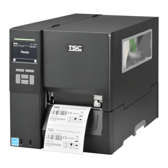
TSC MH241 Series Service Manual
Thermal transfer / dicrect therma industrial barcode printers
Hide thumbs
Also See for MH241 Series:
- User manual (78 pages) ,
- Manual (14 pages) ,
- Programming manual (434 pages)

Related Manuals for TSC MH241 Series


Summary of Contents for TSC MH241 Series
- Page 1 MH241 Series Thermal Transfer / Dicrect Thermal Industrial Barcode Printers Series Lists: MH241/MH341/MH641 Service Manual MH241T/MH341T/MH641T MH241P/MH341P/MH641P...
- Page 2 All other trademarks are the property of their respective owners. Information in this document is subject to change without notice and does not represent a commitment on the part of TSC Auto ID Technology Co. No part of this manual may be reproduced or transmitted in any form or by any means, for any purpose other than the purchaser’s personal use, without the...
-
Page 3: Table Of Contents
Table of Contents 1. Fundamental of the System ....................................1 1.1 Printer Overview ......................................1 Front View ........................................1 Interior View ........................................2 Rear View ........................................4 2. Electronics .........................................5 2.1 Summary of the Board Connectors ................................5 2.2 Interface Pin Configuration ...................................7 3. Mechanism ........................................9 3.1 Remove the Lower Front Panel ..................................9 3.2 Remove the Electronics Cover ................................... - Page 4 3.10 Replacing the Label Supply Spindle (3” and 1”) ............................20 3.11 Replacing the Internal Rewinder DC Motor .............................. 22 3.12 Replacing GPIO Interface Board (with Parallel Port) ..........................23 3.13 Replacing the Main Board ..................................25 3.14 Replacing the Stepping Motor Assembly ..............................26 3.15 Replacing the Gap/Black Mark Sensor Module ............................
-
Page 6: Fundamental Of The System
1. Fundamental of the System 1.1 Printer Overview Front View MH241T Series MH241 Series MH241P Series LED indicator LED indicator LED indicator LCD display LCD display LCD display Front panel buttons Front panel buttons Front panel buttons USB host x 2... -
Page 7: Interior View
Interior View MH241/MH241T Series Ribbon rewind spindle Print head pressure position adjustment knob Print head pressure adjustment knob Print head release lever Ribbon supply spindle Label supply spindle Media near end sensor (movable, MH241T Series only) Label roll guard External label entrance chute Damper Print head Platen roller... - Page 8 For MH241P Series Ribbon rewind spindle Print head pressure position adjustment knob Print head pressure adjustment knob Print head release lever Ribbon supply spindle Label supply spindle Media near end sensor (movable, MH241T/MH241P Series only) Label roll guard Media guide bar & rear label guide Media rewind guide Media rewind spindle External label entrance chute...
-
Page 9: Rear View
Rear View MH241P Series MH241/MH241T Series External label entrance chute External label entrance chute RS-232C interface Slot-in Wi-Fi module (Option) Ethernet interface RS-232C interface USB interface Ethernet interface USB interface microSD card slot microSD card slot Centronics interface (Option) Centronics interface (Option) GPIO interface (Option) Power switch Slot-in Wi-Fi interface (Option) -
Page 10: Electronics
2. Electronics 2.1 Summary of the Board Connectors Main board for MB240/ MB240T Series... - Page 11 Connector Description USB Host connector Power supply output (5V/36V DC) connector Wi-Fi Module connector Parallel Port board connector GPIO interface board connector Head open sensor connector Gap sensor connector Ribbon encoder sensor connector Power supply output (24V DC) connector Lower BM Sensor connector Paper Distance Sensor connector BT module connector Print head connector...
-
Page 12: Interface Pin Configuration
2.2 Interface Pin Configuration RS-232C CONFIGURATION +5 V USB Device CONFIGURATION... - Page 13 Ethernet CONFIGURATION Cutter/peel-off Sensor Connector Description Voltage 0V: Cutter work Cutter enable 5V: Cutter stop 0V: Cutter positive cut Cutter direction 5V: Cutter negative cut 0V: Cutter stop 9 7 4 3 1 Cutter position sensor switch 3.3V: Cutter work Peel sensor receiver A/D: 0~3.3V 1 0 8 6 4 2...
-
Page 14: Mechanism
3. Mechanism 3.1 Remove the Lower Front Panel Open the media cover. Remove 2 screws (fastened by 7.5 kg±15% kg-cm) and pull out the lower front panel. Reassemble the parts in the reverse procedures. Lower front panel... -
Page 15: Remove The Electronics Cover
3.2 Remove the Electronics Cover Turn the printer to backside and remove one screw (fastened by 5 kg±15% kg-cm) on the electronic cover. Turn back the printer to front side and push the electronics cover forward to leave the loading slot, then pull up the cover with both hands to release the mechanism. -
Page 16: Replacing The Power Supply Unit
3.3 Replacing the Power Supply Unit Refer to section 3.2 to remove the electronics cover. Remove 5 screws (fastened by 7.5 kg±15% kg-cm) as indicated below. Remove cables. Remove/Replace the power supply unit. Reassemble the parts in the reverse procedures. -
Page 17: Removing The Media Cover
3.4 Removing the Media Cover Open the media cover and remove 4 screws (fastened by 5 kg±15% kg-cm) from each hinge. Be careful the media cover may fall out from the printer when all screws are disengaged. Take out the media cover from the printer. Reassemble the parts in the reverse procedures. -
Page 18: Replacing The Platen Roller Assembly
3.5 Replacing the Platen Roller Assembly Open the printer cover. Push the print head release lever to open the print head mechanism. Refer to section 3.1 to remove the lower front panel. - Page 19 Use tools to Remove the platen roller dust cap as indicated. Pull up and remove platen roller assembly. Push the platen roller across the slot by holding both the bar and platen roller to left side and lift up the platen roller about 2mm until the black bar has left the slot. Next, release the platen roller assembly by pulling both platen roller and black bar to the right side and the platen roller can be removed.
-
Page 20: Replacing The Print Head Ass'y
3.6 Replacing the Print head ASS’Y Open the printer cover and print head release lever. Release the print head assembly by using key or tools to push the hook to the right side as indicated. - Page 21 Carefully disconnect connectors from the print head assembly. Please do not pull the cable to right and left side alternatively in order to disconnect it from the print head connector. Please push the key in the middle of the connector. Remove/Replace the print head assembly.
-
Page 22: Replacing The Lcd Panel Cover Assembly
3.7 Replacing the LCD Panel Cover Assembly Follow the previous steps (refer to section 3.2 and 3.3) to remove the electronics cover and the power supply unit. Remove 2 screws (fastened by 7.5 kg±15% kg-cm) on left front panel cover and disconnect 2 connectors on LCD panel and USB host board. -
Page 23: Replacing The Lcd Control Board & Lcd Touch Panel
3.8 Replacing the LCD Control Board & LCD Touch Panel Follow the previous step (refer to section 3.7) to remove the LCD panel module. Remove the FPC harness from the LCD control board. Remove the marked six fixed screws (fastened by 5 kg±15% kg-cm) to take out LCD control board, the holder and touch panel can be removed.Reassemble the parts in the reverse procedures. -
Page 24: Replacing Front Panel Buttons Control Board
3.9 Replacing Front Panel Buttons Control Board Refer to section 3.8 to remove the LCD Control Board & LCD Touch Panel. Remove the front panel buttons control board located below the LCD Panel module. Front Panel Buttons Control Board Reassemble the parts in the reverse procedures. -
Page 25: Replacing The Label Supply Spindle (3" And 1")
3.10 Replacing the Label Supply Spindle (3” and 1”) Refer to section 3.2 to remove the electronic cover. Uninstall the power supply unit by remove 5 screws (fastened by 7.5 kg±15% kg-cm) on the main board and interface as indicated below. Remove the 7 screws (fastened by 7.5 kg±15% kg-cm), 2 hex socket cap screws (fastened by 7.5 kg±15% kg-cm), and 1 copper pillar (fastened by 7.5 kg±15% kg-cm) to uninstall the main board as indicated. - Page 26 Remove the 2 hex socket cap screws (fastened by 10.5 kg±15% kg-cm) on the electronic side to release the label supply spindle assembly. For 1” core label spindle, remove the screw of the spindle from the stand. Remove the spindle and install the 1” core label spinel into the slot Lock the screw on the side of the spindle and lock 2 screws on the back of the stand.
-
Page 27: Replacing The Internal Rewinder Dc Motor
3.11 Replacing the Internal Rewinder DC Motor Please refer to section 3.3 to remove the power supply unit and you can see the DC motor. Remove the 2 marked fix screws (fastened by 7.5 kg±15% kg-cm) from the DC motor. Remove 2 DC motor cable connectors on the main board. -
Page 28: Replacing Gpio Interface Board (With Parallel Port)
3.12 Replacing GPIO Interface Board (with Parallel Port) Refer to section 3.2 to remove the electronics cover. Refer to section 3.3 to remove the power supply unit. Remove the original GPIO interface board (screws torque: 7.5 kg±15% kg-cm) or protective cover as below. Install the GPIO interface board from the outside of interface board. - Page 29 Fasten the cables on GPIO interface board as indicated. Fix the two screws (7.5 kg±15% kg-cm) on GPIO interface board as indicated. Remove/Replace the GPIO interface board. Reassemble the parts in the reverse procedures.
-
Page 30: Replacing The Main Board
3.13 Replacing the Main Board Refer to section 3.2 to remove the electronics cover. Refer to section 3.3 to remove the power supply unit. Refer to section 3.12 to remove the GPIO interface board (if installed). Remove the 2 screws (fastened by 7.5 kg±15% kg-cm) and 2 hexagon screws. Remove 1 copper pillar, 5 screws (fastened by 7.5 kg±15% kg-cm), and all connectors from the main board. -
Page 31: Replacing The Stepping Motor Assembly
3.14 Replacing the Stepping Motor Assembly Refer to section 3.2 to remove the electronics cover. Remove 4 screws (fastened by 10.5 kg±15% kg-cm) on the stepping motor assembly. Unplug the cable on the motor. Screws Connector Remove/Replace the stepping motor assembly (including belt, gears, and stepping motor). Reassemble the parts in reverse procedures. -
Page 32: Replacing The Gap/Black Mark Sensor Module
3.15 Replacing the Gap/Black Mark Sensor Module Refer to section 3.2 to remove the electronics cover. Disconnect the gap/black mark sensor connectors from the main board. Pull out the media sensor module. Remove/Replace the gap/black mark sensor. Media sensor assembly Gap/Black mark sensor connector Reassemble the parts in the reverse procedures. - Page 33 Plastic tab Remove/Replace the gap/black mark sensor. Reassemble the parts in the reverse procedures.
-
Page 34: Cutter Module Installation (Option)
3.16 Cutter Module Installation (Option) Refer to section 3.1 to remove the lower front panel. Remove the lower fixed bar by disengage the 2 screws (fastened by 7.5 kg±15% kg-cm). Plug the cutter cable connector into the cutter/peel-off cable socket. Put 2 locating protrusions into locating holes as indicated. Fasten the 2 black fixing bolts and 2 screws (7.5 kg±15% kg-cm) to fix the cutter module then closed the plate. - Page 35 Reassemble the parts in the reverse procedures. Regular guillotine cutter Heavy duty guillotine cutter module module Care Label Cutter Rotary Cutter...
-
Page 36: Peel-Off Kit Installation (Option)
3.17 Peel-off Kit Installation (Option) Peel-off Kit parts list: Peel-off roller module Media guide bar & rear label guide module Peel-off sensor module Internal liner rewinder module 2 black fixing bolts and 9 screw... - Page 37 Peel-off Sensor Module Installation Refer to section 3.1 to remove the lower front panel. Remove the 2 screws and uninstall the lower fixed bar (fastened by 7.5 kg±15% kg-cm). Install the peeler roller on the slot, then fix the screw (7.5 kg±15% kg-cm) as indicated. Note: The screw must close to the roller ring to fix it and preventing roller loosen when peeling the label.
- Page 38 Fasten 2 set bolts (7.5 kg ±15% kg-cm) and 2 screws (7.5 kg±15% kg-cm) into the fixing holes, then close the peel-off module. Fix the rest 2 screws through the reserved holes. Connect the power cord and complete peel-off sensor module installation. Remove/Replace the peel-off sensor module by the above reverse procedures.
- Page 39 Rewind Spindle and Media Guide Bar Installation Remove 4 screws (10.5 kg±15% kg-cm) as indicated and take out the rewind spindle cover. Connect the cable to the rewinder power connector (white) as indicated. Using 4 screws which come with module to fix the whole rewind spindle module.
- Page 40 Media Guide Bar Installation Refer to section 3.2 to remove the electronic cover. Use the screw driver to push out the black rubber cover on the hole in electronic side as indicated. Install the media guide bar assembly and use tool to fasten it. Reassemble the parts in the reverse procedures.
-
Page 41: Slot-In Wireless Housing Installation (Option)
3.18 Slot-in Wireless Housing Installation (Option) ※ Before replacing the new Wi-Fi module, please set the default to clear the old Wi-Fi settings in the printer via TSC Console. And you need to reset the Wi-Fi settings after replacing the new Wi-Fi module. - Page 42 Refer to section 3.2 to remove the electronics cover. Unscrew 2 screws to take out the housing cover. Install the housing. Make cables go through the slot first, then connect to the main board. Push the housing in the slot and fasten 2 screws. Insert the wifi module and fasten 2 screws as shown.
- Page 43 Connect the slot-in wireless transfer module housing board cable to the main board as indicated. Slot-in Wi-Fi module with antenna and transfer board Remove/Replace the Slot-in Wi-Fi module. Reassemble the parts in the reverse procedures.
-
Page 44: Replacing The Bluetooth Module
3.19 Replacing the Bluetooth module Refer to section 3.2 to remove the electronics cover. Refer to section 3.3 to remove the power supply unit. Refer to section 3.12 to remove the GPIO interface board (if installed). Plug the Bluetooth module cable to the connector as indicated. Please load the Bluetooth cable through the path as indicated. - Page 45 Remove the two screws (fastened by 7.5 kg±15% kg-cm) on the left front panel cover and install the Bluetooth module to the lower panel as indicated. Connect the Bluetooth and Bluetooth cable and then fix it to the front panel (3 kg±15% kg-cm) as below. Fix the left front panel cover and complete the installation of Bluetooth module.
-
Page 46: Care Label Cutter Module Installation (Option)
3.20 Care Label Cutter Module Installation (Option) Refer to section 3.1 to remove the lower front panel. Please replace the tear bar used with care label cutter module by remove the 2 screws as indicated. Remove the lower fixed bar by disengage the 2 screws (fastened by 7.5 kg±15% kg-cm). Plug the cable connector of care label cutter into the cutter/peel-off cable socket. - Page 47 Fasten the 2 black fixing bolts and 2 screws (7.5 kg±15% kg-cm) to fix the cutter module then closed the plate. Fasten the 1 limit screw (7.5 kg±15% kg-cm) and the rest 2 screws (7.5 kg±15% kg-cm) on cutter module plate as indicated. Fixing bolts Limit screw Screws...
-
Page 48: Internal Rewinder Module Installation (Option, Mh241/Mh241T Series Only)
3.21 Internal Rewinder Module Installation (Option, MH241/MH241T Series Only) Overview: This one uses on the 1.5” media supply spindle. This one uses on the 1.” media supply spindle. - Page 49 Refer 3.2 to remove electronic cover. Refer 3.3 to remove power supply unit. Unscrew 4 marked screws. Install the media rewind spindle and screw the marked 4 screws. Connect the cable to the motor’s board.
- Page 50 Put the power supply unit back. Take off the lid on the marked position. Take off the lid on the marked position. Install and tighten up the upper media guide bar...
- Page 51 Install the lower media guide’s screw in marked potion. Combine the lower media guide bar and the screw. Refer 3.1 to remove lower front cover. Install the front cover for rewinder module. Screw the marked 3 screws. Remove the parts in reverse procedures.
-
Page 52: Troubleshooting
4. TroubleShooting Problem Possible Cause Recovery Procedure Plug the power cord in printer and outlet. The power cord is not properly connected. Power indicator does not illuminate The power switch is closed. Switch the printer on. ... - Page 53 mechanism. If peeler module is installed, please remove the label. If there is no peeler module in front of the printer, please Peel function is enabled. Take Label switch off the printer and install it. Check if the connector is plugging correctly. Can’t downloading the file to ...
- Page 54 Sensor sensitivity is not set properly. Calibrate the sensor by Auto Gap or Manual Gap options. The media sensor is covered with dust. Clear the GAP/Black mark sensor by blower. Printhead pressure is incorrect. Please refer to the chapter 4.
-
Page 55: Knob Adjustment
4.1 Knob Adjustment Printhead Pressure Adjustment Knob has 5 levels’ adjustment.Different number means different pressure to the springs . Due to media is aligned to the inbound of the printer mechanism, different media width requires the different pressure. Users can try which level can meet their expectation. -
Page 56: Ribbon Tension Adjustment Knob
4.2 Ribbon Tension Adjustment Knob Ribbon Tension Adjustment Knob has 5 positions for adjustment. Due to the ribbon is aligned to the inbound of print mechanism, different width of ribbons may need to adjust the tension adjustment knob to avoid the ribbon wrinkle and get the best print quality. -
Page 57: Mechanism Fine Adjustment To Avoid Ribbon Wrinkles
4.3 Mechanism Fine Adjustment to Avoid Ribbon Wrinkles Ribbon wrinkle is related to the media width, thickness, print head pressure balance, ribbon film characteristics, print darkness setting…etc. In case the ribbon wrinkle happens, please follow the instructions below to adjust the printer parts. Ribbon Tension Adjustment Knob has 5 positions for adjustment. - Page 58 Wrinkle happens from label lower right to upper left direction Feed Direction Make sure the Print Head Pressure Adjustment Knob is in correct position for the current media. Ex: 1~2”, 3~4” Turn the screw clockwise per level and print to see if the winkle has gone. If the ribbon tension adjustment knob has positioned on the level of innermost side but dosnt’t improve the ribbon wrinkle, ...
- Page 59 Wrinkle happens from label lower left to upper right direction Feed Direction Make sure the Print head Pressure Adjustment Knob is in correct position for the current media. Ex: 1~2”, 3~4” Turn the screw counterclockwise per level and print to see if the winkle has gone. ...
-
Page 60: Maintenance
5. Maintenance This session presents the clean tools and methods to maintain the printer. For Cleaning Depending on the media used, the printer may accumulate residues (media dust, adhesives, etc.) as a by-product of normal printing. To maintain the best printing quality, you should remove these residues by cleaning the printer periodically. Regularly clean the print head and supply sensors once change a new media to keep the printer at the optimized performance and extend printer life. - Page 61 Cleaning Tools Cotton swab Lint-free cloth Brush with soft non-metallic bristles Vacuum cleaner 75% Ethanol (for disinfecting) 99% Isopropyl alcohol (for printhead and platen roller cleaning) Genuine printhead cleaning pen Mild detergent (without chlorine) Cleaning Process: Printer Part Method...
-
Page 62: Revise History
Revise History Date Content Editor...
Need help?
Do you have a question about the MH241 Series and is the answer not in the manual?
Questions and answers