Table of Contents
Advertisement
Quick Links
Advertisement
Table of Contents

Related Manuals for Leica DISTO X6


Summary of Contents for Leica DISTO X6
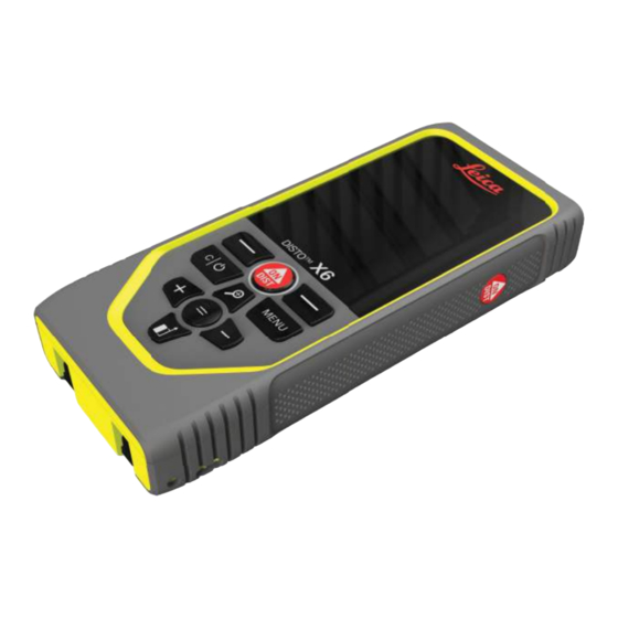
- Page 1 Leica DISTO™ X6 The original laser distance meter User Manual Version 1.0 English...
- Page 2 This manual applies to the Leica DISTO™ X6. Where there are differences between the standard setups they are clearly described. Leica Geosystems On the last page of this manual, you can ond the address of Leica Geosystems address book headquarters. For a list of regional contacts, please visit...
-
Page 3: Table Of Contents
Table of Contents Safety Directions General Introduction Deonition of Use Limits of Use Responsibilities Hazards of Use Laser Classiocation Overview Instrument Setup Operation Settings Functions Message Codes Care Technical Data Conformity to National Regulations International Limited Warranty Table of Contents... -
Page 4: Safety Directions
Safety Directions Safety Directions General Introduction Description The following directions enable the person responsible for the product, and the person who actually uses the equipment, to anticipate and avoid operational hazards. The person responsible for the product must ensure that all users understand these directions and adhere to them. -
Page 5: Deonition Of Use
Type Description Indicates a potentially hazardous situation or an WARNING unintended use which, if not avoided, could result in death or serious injury. Indicates a potentially hazardous situation or an CAUTION unintended use which, if not avoided, may result in minor or moderate injury. - Page 6 Opening the product using tools, for example a screwdriver, unless this is permitted for certain functions • Use with accessories from other manufacturers without the prior written explicit approval of Leica Geosystems AG • Modiocation or conversion of the product Deliberate dazzling of third parties; also in the dark •...
-
Page 7: Limits Of Use
Responsibilities Manufacturer of the Leica Geosystems AG, CH-9435 Heerbrugg, hereinafter referred to as Leica Geosystems, product is responsible for supplying the product, including the User Manual and original accessor- ies, in a safe condition. -
Page 8: Hazards Of Use
▶ Although the product meets the strict regulations and standards which are in force in this respect, Leica Geosystems AG cannot completely exclude the possibility that other equipment can be disturbed or that humans or animals can be affected. ▶... - Page 9 WARNING Improper disposal If the product is improperly disposed of, the following can happen: If polymer parts are burnt, poisonous gases are produced which may impair health. • If batteries are damaged or are heated strongly, they can explode and cause poison- •...
- Page 10 Precautions: ▶ Although the product meets the strict regulations and standards which are in force in this respect, Leica Geosystems cannot completely exclude the possibility that other equipment may be disturbed. ▶ The product is a class A product when operated with the internal batteries. In a domestic environment this product may cause radio interference in which case the user may be required to take adequate measures.
-
Page 11: Laser Classiocation
NOTICE Target surfaces Measuring errors and increase of measuring time can occur. Precautions: ▶ Keep in mind that measuring errors can occur when measuring to colourless liquids, glass, styrofoam or permeable surfaces or when aiming at high gloss surfaces. ▶ Against dark surfaces the measuring time increases. - Page 12 Safety Directions CAUTION Class 2 laser product From a safety perspective, class 2 laser products are not inherently safe for the eyes. Precautions: ▶ Avoid staring into the beam or viewing it through optical instruments. ▶ Avoid pointing the beam at other people or at animals. ▶...
-
Page 13: Overview
Overview Components The Leica DISTO™ is a laser distance meter operating with a class 2 laser. See chapter 9 Technical Data for scope of use. Display/Touch screen ON/DIST, ON/Measure Left selection key linked to symbols above Clear/OFF Zoom/Navigate upwards/Pointonder Add/Navigate left... - Page 14 Overview Basic measuring screen Pointonder on Pointonder off Status bar Favourite, left key Active function Cross hair Favourite, right key Measuring results Selection screen Red icons represent Functions ☞ Black icons represent Settings Function/Settings menu Touch icon or press the left selection key to switch between Function/Settings menu.
- Page 15 Basic result screen Back step-by-step. For example: Repeat measurement Repeat function For example: Repeat whole measurement Save result. Check saved results in the REPORTS menu. Option: For some functions to measure multiple points Icons on status bar Time Gesture control Bluetooth is switched on Scroll up/down for further results Bluetooth connection established...
-
Page 16: Instrument Setup
Instrument Setup Instrument Setup Charging the Li-Ion Charge the battery before using it for the orst time. battery by USB Use the original charging cable only. ☞ Plug the small end of the cable into the port of the device, and plug the end of the charger into an electrical socket. - Page 17 • It is normal for the battery to become warm during charging. Using the chargers recommended by Leica Geosystems, it is not possible to charge the battery once the temperature is too high For new batteries or batteries that have been stored for a long time (> three •...
- Page 18 Instrument Setup Switching ON/OFF Device is turned ON. Device is turned OFF. If the device does not react anymore or cannot be switched off, press and hold ☞ the C/Off key for about 10 s. After releasing the button, the device restarts. Start-up wizard This wizard starts automatically when switching the device ON the very orst time or after a Reset.
- Page 19 Clear Leave current function, go to default operation mode. Message codes NOTICE If the message "i" appears with a number, observe the instructions in 7 Message Codes section. Instrument Setup...
- Page 20 Instrument Setup Example: Multifunctional When measuring with 90° nipped-out endpiece, make sure that it lies plane ☞ endpiece against the edge you measure from. Example: The orientation of the endpiece is automatically detected and the zero point is ☞ adjusted accordingly.
- Page 21 Adjusting measuring reference Adjusting the measuring reference only works ☞ in pointing mode. Make sure that the laser is switched on. Distance is measured from the rear of the device (standard setting) Distance is measured from the front of the device Distance is measured from the tripod thread Conorm setting.
-
Page 22: Operation
Operation Operation Using the touch screen Use only ongers to use the touch screen • Do not allow the touch screen to come into contact with other electrical devices • Electrostatic discharges can cause the touch screen to malfunction • Do not allow the touch screen to contact water. - Page 23 Spread two ongers apart to zoom if pointonder is acti- vated. Instead of using the touch screen, the normal keypad keys can be used also. ☞ Single DISTANCE Aim active laser at target. Measured distance Operation...
- Page 24 Operation Permanent/minimum- maximum measuring Used to measure room diagonals (maximum val- min. max. 2 sec ues) or horizontal distance (minimum values). Live view The minimum distance measured The maximum distance measured Main line: The current value measured Stops permanent/minimum-maximum measuring. The measuring results are displayed.
- Page 25 Use the Down navigation key to take over ☞ values in the main line for sending by Bluetooth. Exit Add/subtract The next measure- ment is added to the previous one The next measure- − ment is subtracted from the previous Operation...
- Page 26 Operation Push the Enter/Equal key to stop adding/substracting values. This process can be repeated as required. The same process can be used for ☞ adding or subtracting areas or volumes. Bluetooth data DISTO™ Plan. Use App for Bluetooth data transfer. Your device can also be transfer updated through this App.
- Page 27 Bluetooth 4.0 or higher. The number of possible measurements with only one battery charge is hardly affected due to the Low Energy technology. Following software and app are available from Leica Geosystems. They extend the pos- sibilities arising with the use of Leica DISTO™: DISTO™...
- Page 28 Operation We provide no warranty for free Leica DISTO™ software and offer no support ☞ for it. We accept no liability whatsoever arising from the use of the free soft- ware and we are not obliged to provide corrections nor to develop upgrades.
-
Page 29: Settings
Settings Overview Press the MENU key twice to enter the settings menu. Settings Activate/deactivate KEY LOCK GESTURE ON/OFF BEEP ON/OFF ANGLE UNITS BLUETOOTH ON/OFF DISTANCE UNITS FAVORITES BLUETOOTH SETTINGS Settings... - Page 30 Settings DISTANCE OFFSET DATE/TIME LANGUAGE RESET DEVICE DISPLAY ILLUMINATION INFORMATION SCREEN ROTATION TILT CALIBRATION SHUTDOWN TIME Switch TOUCH SCREEN ON/OFF...
- Page 31 Point昀椀nder Activate/deactivate KEY LOCK An activated key lock stays active even if the device is switched off. Toggle ON/OFF Exit settings. Settings...
- Page 32 Settings If KEY LOCK is activated: Press the = key after device is switched on to access ☞ device. GESTURE ON/OFF This feature allows triggering measurements without touching the device. To do so, wipe through laser beam with hand or other object within 25 cm. Toggle ON/OFF Exit settings.
- Page 33 ANGLE UNITS Exit settings. Refuse Conorm BLUETOOTH ON/OFF Toggle ON/OFF Exit settings. Settings...
- Page 34 Settings When Bluetooth is switched on, a black Bluetooth icon is displayed in status ☞ bar. Once connection is established, the colour of the icon changes to blue. DISTANCE UNITS Toggle between the units. Example Conorm setting. Exit settings.
- Page 35 FAVORITES Select favourite function. Press the left or right selection key. Function is set as favourite above the corresponding selection key. Exit settings. Settings...
- Page 36 Settings BLUETOOTH SETTINGS BT SETTINGS - KEYBOARD MODE Select ON or OFF. Enables measurements to be transmitted as entered on an external keyboard to a computer, tablet or Conorm setting. smartphone. BT SETTINGS - BT NAVIGATION If activated, it is possible to send measurements manually by using the right favourite key.
- Page 37 BT SETTINGS - DECIMAL SEPARATOR Select kind of decimal point for transmitted value. Conorm setting. BT SETTINGS - UNITS TRANSFER Select if unit is transmitted or not. Conorm setting. For example, move between cells when working with Microsoft Excel. A long press/ hold of the corresponding favourite key, starts the function as shown on the display (grey colour).
- Page 38 Settings BT SETTINGS - TERMINATION AFTER VALUE Select termination of transmission. Conorm setting. BT SETTINGS - AUTOSEND Select if value is transmit- ted automatically or manu- ally. Conorm setting. Exit settings.
- Page 39 Depending on the chosen settings for Keyboard mode and Autosend, some ☞ selection points might be skipped. DISTANCE OFFSET An offset adds or subtracts a specioed value automatically to or from all measurements. This function allows tolerances to be taken into account. The offset icon is displayed. Select digit.
- Page 40 Settings DATE/TIME Conorm setting. Conorm setting.
- Page 41 10 11 Exit settings. LANGUAGE Conorm setting. Exit settings. Settings...
- Page 42 Settings RESET DEVICE Reset returns the instrument to the factory settings. All customised settings and memor- ies are lost. Refuse Conorm DISPLAY ILLUMINATION Select brightness.
- Page 43 To save power, reduce bright- ☞ ness if not necessary. Conorm setting. Exit settings. SCREEN ROTATION Toggle ON/OFF Exit settings. Settings...
- Page 44 Settings Example INFORMATION...
- Page 45 This icon appears on the screen once the Leica DISTO™ X6 is operated without an adapter. Refer to Tilt Sensor for details. This icon appears on the screen once the Leica DISTO™ X6 is mounted on a Leica DST 360‑X. Refer to DST 360-X CALIBRATION for details.
- Page 46 Settings Place device on absolutely nat surface. Once onished, press the ON/DIST key. Follow the instructions on the screen. 180° Turn the device horizontally by 180° and place it again on absolutely nat surface.
- Page 47 Once onished, press the ON/DIST key. Follow the instructions on the screen. Place device on absolutely nat surface. Once onished, press the ON/DIST key. Follow the instructions on the screen. Settings...
- Page 48 Settings Turn the device horizontally by 180° and place it again 180° on absolutely nat surface. Once onished, press the ON/DIST key. After 2 s, the device goes back to the basic ☞ mode.
- Page 49 DST 360-X CALIBRATION For levelling, the device must be in an inclination range of ±5°. Roughly level the device on the Leica DST 360‑X horizontally. Aim at a target in approximately 5 m distance. Push ON/DIST for measurement. Flip the device by 180°.
- Page 50 Settings Rotate the device by 180°. Flip the device by 180° and aim at the same tar- get as in the previous measurement. Push ON/DIST for measurement. Flip the device by 180°. 10 Rotate the device by 180° and aim very accurate at the same target as in the previous measure- ment.
- Page 51 SHUTDOWN TIME Deone time when device shall switch off automatically. Exit settings. Refuse Conorm Settings...
- Page 52 Settings Switch TOUCH SCREEN ON/OFF Toggle ON/OFF Exit settings. Point昀椀nder This feature is a great help for outdoor measuring. The integrated pointonder (view screen) shows the target on the display. The device measures in the middle of the crosshair, even if the laser dot is not visible. Parallax errors occur when the pointonder camera is used on close targets, with ☞...
- Page 53 Option 2: Toggle ON/OFF Exit settings. Adjust zoom while toggling the zoom key. The zoom stage is shown. Adjust illumination with navigation keys left and right. The DISPLAY ILLUMINA- TION value is shown. Settings...
-
Page 54: Functions
Functions Functions Overview LEVELLING SMART HORIZONTAL HEIGHT TRACKING AREA Single DISTANCE VOLUME TRIANGLE AREA TIMER REPORTS HEIGHT PROFILE SLOPE STAKE OUT MIP - WIDTH... - Page 55 MIP - AREA MIP - DIAMETER POINT TO POINT POINT TO POINT - LEVELLED POINT TO LINE 2) 3) 3D DATA CAPTURING P2P - FILES SMART AREA Activated, when connected to Leica DST 360‑X adapter DXF and CSV Functions...
- Page 56 Functions Close/exit all functions described in this chapter as follows: Leave menu. Exit. LEVELLING Displays inclinations of 360°. Instrument beeps at 0°. Ideal for horizontal or vertical adjustments.
- Page 57 SMART HORIZONTAL Up to 360° and a trans- Aim laser at target. verse tilt of ±10°. Measured distance, x Angle, α Height difference from measuring point, y Horizontal distance, z Save result. Check saved results in the REPORTS menu HEIGHT TRACKING Heights of buildings or trees without suitable renective points can be determined.
- Page 58 Functions Aim laser at lower point. Aim laser at upper points and angle/height tracking starts automatically. Distance P0 Angle α Angle β Tracking height y if device is turned on tripod Save result. Check saved results in the REPORTS menu...
- Page 59 Distance z Use the Down navigation key to take over values in the main line for sending ☞ by Bluetooth. AREA Aim laser at orst target point. Functions...
- Page 60 Functions First distance Second distance Circumference Area Save result. Check saved results in the REPORTS menu Aim laser at second target point. The main result is the area of this rectangle. The individual measured values are ☞ shown above the main line. Partial measurements/painter function: Press + or −...
- Page 61 Measured distance VOLUME Aim laser at orst target point. Aim laser at second target Aim laser at third target point. point. Functions...
- Page 62 Functions Circumference Ceiling/noor area Wall areas Volume Save result. Check saved results in the REPORTS menu Volume First distance Second distance Third distance More results. TRIANGLE AREA Aim laser at orst target point.
- Page 63 Aim laser at second target Aim laser at third target point. point. First distance Second distance Third distance Angle between orst and second measurement Save result. Check saved results in the REPORTS menu Circumference Triangular area More results. Functions...
- Page 64 Functions The main result is the area of this triangle. With + or − several triangle can be ☞ added or subtracted. Refer to Add/subtract TIMER Select release time. The timer starts once the ON/DIST key is pressed. The countdown is dis- •...
- Page 65 Number of reports available Type of report Screenshot of last measuring point Delete one or all reports Toggle between available reports. Check measuring details of the selected report. Functions...
- Page 66 Functions HEIGHT PROFILE Start measuring. First measurement is the reference point Set absolute height of reference point. Example: Height above sea level Aim at reference point (REF). Step back to read out previous meas- 2 × uring points Horizontal distance to device = d Height difference to reference point...
- Page 67 Push the ON/DIST key for > 2 s for continuous height proole measuring. ☞ Ideal for measuring of height differences to a reference point. Can be also used ☞ to measure prooles and terrain sections. After measuring the reference point, the horizontal distance and height is displayed for each following point.
- Page 68 Functions SLOPE Aim laser at upper target point. Aim laser at lower target point. Horizontal distance between both points Vertical height between both points Included angle between both points Distance between both points Save result. Check saved results in the REPORTS menu...
- Page 69 P1 angle P1 distance P2 angle P2 distance Save result. Check saved results in the REPORTS menu Indirect distance measuring between two points with additional results. Ideal ☞ for applications such as length and slope of roof, height of chimneys,… It is important, that the instrument is positioned in the same vertical plane as the two measured points.
- Page 70 Functions Adjust distance a. Adjust distance b. Start measuring. Move Press = to approve Press = to approve device slowly along the STAKE-OUT - "a". STAKE-OUT - "b". stake out line. The distance to the previous/next stake out point is displayed. # of previous stake out Distance to previous stake out Total distance...
- Page 71 MIP - WIDTH It is absolutely necessary to aim with the laser per- pendicular to the object. 4× 2× 1× If necessary, use the Zoom Select arrows with the for precise aiming. right favourite key or by tapping on the display. Adjust for measurement by arrow keys or on touch screen.
- Page 72 Functions Distance to object Width between the two arrow positions Save result. Check saved results in the REPORTS menu Conorm measurement. Corresponding width is cal- culated. MIP - AREA Aim perpendicular to the horizontal centreline of the area. This area must be perfectly nat on the ver- tical plane.
- Page 73 4× 2× 1× If necessary, use the Zoom Select arrows with the for precise aiming. right favourite key or by tapping on the display. Adjust for measurement by arrow keys or on touch screen. Width between the two arrow positions Length between the two arrow positions Circumference Area...
- Page 74 Functions Distance MIP - DIAMETER Ø Aim laser perpendicular to the middle of the round object.
- Page 75 4× 2× 1× If necessary, use the Zoom Select arrows with the for precise aiming. right favourite key or by tapping on the display. Adjust for measurement by arrow keys or on touch screen. Distance to object Circumference Circular area Diameter Save result.
- Page 76 Functions POINT TO POINT The POINT TO POINT measurement function is activated when connected to the Leica DST 360‑X. Aim laser at orst target point. Aim laser at second target point.
- Page 77 2 sec chosen, live measured distance values are displayed. POINT TO POINT - This function is activated when connected to the Leica DST 360‑X adapter. LEVELLED Use this POINT TO POINT - LEVELLED measurement function to get more measuring data. Do not move device after levelling. The tie distance is calculated based on two known coordinates with x, y and z value.
- Page 78 The colour of the bubble must be in an inclination indicates the levelling range of ±5°. status. Red: Not levelled. Adjust the Leica DST 360‑X. Rotate the device clock- Rotate the device clock- A green bubble indicates wise 90°. Follow the wise 90°.
- Page 79 Aim laser at orst target point. Aim laser at second target point. Vertical height between both points Horizontal distance between both points Angle between both points Distance between both points Save result. Check saved results in the REPORTS menu Functions...
- Page 80 Functions Distance between both points Distance to the orst target point Distance to the second target point Height between orst and second target point Use the Down navigation key to take over values in the main line for sending ☞ by Bluetooth.
- Page 81 The colour of the bubble must be in an inclination indicates the levelling range of ±5°. status. Red: Not levelled. Adjust the Leica DST 360‑X. Rotate the device clock- Rotate the device clock- A green bubble indicates wise 90°. Follow the wise 90°.
- Page 82 Functions POINT TO LINE - start measurement Aim at the starting point, orst point of the reference line. Aim at the second point along the reference line. Length of reference line Distance to second point...
- Page 83 Conormation: Reference Aim at the point of line has been deoned. interest, POI. Depending on the position of the POI, measurement res- ults may show positive and/or negative values. Distance from starting point on reference line to 90° projection of POI Distance from POI to reference line The measuring results disappear after 2 sec.
- Page 84 Functions Interpreting results: 1: starting point, 2: second point Distance from starting point on reference line to 90° projection of POI: a > 0 Distance from POI to reference line: b > 0 1: starting point, 2: second point Distance from starting point on reference line to 90°...
- Page 85 1: starting point, 2: second point Distance from starting point on reference line to 90° projection of POI: a < 0 Distance from POI to reference line: b > 0 3D DATA CAPTURING Measure CAD oles like DXF to be used in CAD programs or user-specioc software. •...
- Page 86 Functions Adjust the Leica DST 360‑X. Rotate the device clock- Rotate the device clock- A green bubble indicates wise 90°. Follow the wise 90°. Follow the correct levelling. instructions on the display. instructions on the display. Check status line: Indicates proper lev-...
- Page 87 Aim at additional points. Stops DXF capture and saves data. Number of measured points Ticks indicate format of results available Time stamp of measurement Finish and save measurement Back, collect more measuring points Finish measurement. Open P2P - FILES. Refer to P2P - FILES for details.
- Page 88 Depending on measured Possible content of the nector cable to connect data, the following direct- DXF directory: ories are available: the Leica DISTO™ X6 to a PC or laptop. • Reports Open the Explorer, search • for the USB connected...
- Page 89 *.csv: Table with polar and cartesian coordinates • IMG_*.jpg: 240 × 240 pixel picture of measured point View/copy/move/backup/transfer data. SMART AREA This function is activated when connected to the Leica DST 360‑X adapter. Aim laser at orst target point. Functions...
- Page 90 Functions Distance between last and previous measured point Distance between last and orst meas- ured point Circumference Aim at additional points. By pressing =, the area is Area Maximum 30. calculated. Save result. Check For correct results, points saved results in the must be measured clock- REPORTS menu...
-
Page 91: Message Codes
Message Codes Overview Code Cause Correction Transverse tilt greater than 10° Hold the instrument without any transverse tilt. Calibration error Make sure the device is placed on an absolutely horizontal and nat sur- face. Repeat the calibration proced- ure. If the error still occurs contact your dealer. - Page 92 Hardware error If this message continuously appears, the device must be ser- viced. Ask dealer for help. 300-303 Error with Leica DST 360‑X Repeat procedure. If the message adapter still occurs, contact your dealer. The device has been moved, level- Perform levelling again.
-
Page 93: Care
Care Clean the device with a damp, soft cloth • • Never immerse the device in water • Never use aggressive cleaning agents or solvents Care... -
Page 94: Technical Data
Technical Data Technical Data General Accuracy with favourable conditions 1 mm/0.04″ Accuracy with unfavourable conditions 2 mm/0.08″ Range with favourable conditions 0.05-250 m/0.16-820 ft Range with unfavourable conditions 0.05-150 m/0.16-500 ft Smallest unit displayed 0.1 mm/ 1/32″ X-Range Power Technology Laser class Laser type 635 nm, <... - Page 95 After user calibration. Additional angle-related deviation of ±0.01° per degree up to ±45° in each quadrant. Applies at room temperature. For the whole operating temperature range, the maximum deviation increases by ±0.1°. In combination with Leica DST 360‑X adapter. Technical Data...
- Page 96 Technical Data Weight (with batteries) 230 g/8.11 oz Temperature range storage −25 to 70 °C/−13 to 158 °F Temperature range operation −10 to 55 °C/14 to 131 °F Charging time Charging temperature 5 to 40 °C Charging power 5 V/1 A Functions Distance measuring Min/Max measuring...
- Page 97 Personalised Favorites Timer Point to point function/distance Smart Area Height tracking Height proole Sloped objects Proole Measurement Gesture Control Point-to-line function CAD data capturing (DXF/CSV/JPG) Measure in Picture In combination with Leica DST 360‑X adapter. Technical Data...
-
Page 98: Conformity To National Regulations
The full text of the EU declaration of conformity is available at the fol- lowing Internet address: http://www.disto.com/ce. UKCA Hereby, Leica Geosystems AG declares that the radio equipment type Leica DISTO™ X6 is following the provisions of the applicable relevant statutory requirement S.I. 2017 No. 1206 Radio Equipment Regulations 2017. - Page 99 This equipment has been tested and found to comply with the limits for a Class B digital instrument, pursuant to part 15 of the FCC rules. These limits are designed to provide reasonable protection against harmful interference in a residential installation. This equipment generates, uses and can radiate radio frequency energy and, if not installed and used in accordance with the instructions, may cause harmful interference to radio communications.
- Page 100 The radiated rf output power of the instrument is below the FCC radio frequency expos- ure limits for portable devices according to KDB 447498. Changes or modiocations not expressly approved by Leica Geosystems for compliance could void the user's authority to operate the equipment.
- Page 101 Others The conformity for countries with other national regulations has to be approved prior to use and operation. Technical Data...
-
Page 102: International Limited Warranty
International Limited Warranty Description International Limited Warranty The Leica DISTO™ X6 comes with a two year warranty from Leica Geosystems AG. To receive an additional year warranty, the product must be registered on our website at Leica Disto Warranty within eight weeks of the purchase date. If the product is not registered, our two year warranty applies. - Page 104 979590-1.0.0en Original text (979590-1.0.0en) Published in Switzerland, © 2023 Leica Geosystems AG Leica Geosystems AG Heinrich-Wild-Strasse 9435 Heerbrugg Switzerland www.leica-geosystems.com...
Need help?
Do you have a question about the DISTO X6 and is the answer not in the manual?
Questions and answers