
Related Manuals for Ruijie Reyee RG-EG1510XS


Summary of Contents for Ruijie Reyee RG-EG1510XS
- Page 1 Ruijie Reyee RG-EG1510XS Router Hardware Installation and Reference Guide Document Version: V1.0 Date: March 26, 2024 Copyright © 2024 Ruijie Networks...
- Page 2 Ruijie Networks reserves the right to modify the content of the document without any notice or prompt. This manual is designed merely as a user guide. Ruijie Networks has tried its best to ensure the accuracy and reliability of the content when compiling this manual, but it does not guarantee that the content of the manual is completely free of errors or omissions, and all the information in this manual does not constitute any explicit or implicit warranties.
-
Page 3: Preface
Intended Audience This document is intended for: Network engineers Technical support and servicing engineers Network administrators Technical Support The official website of Ruijie Reyee: https://reyee.ruijie.com Technical Support Website: https://reyee.ruijie.com/en-global/support Case Portal: https://www.ruijienetworks.com/support/caseportal Community: https://community.ruijienetworks.com... - Page 4 Note This manual provides installation steps, troubleshooting, technical specifications, and usage guidelines for cables and connectors. It is intended for users who want to understand the above and have extensive experience in network deployment and management, and assume that users are familiar with related terms and concepts.
-
Page 5: Table Of Contents
Contents Preface ..............................I 1 Product Introduction .......................... 1 1.1 Overview ............................ 1 1.2 Package Contents........................1 1.3 Appearance ..........................2 1.4 Technical Specifications ......................5 2 Preparing for Installation ........................7 2.1 Safety Precautions ........................7 2.1.1 General Safety Precautions ................... 7 2.1.2 Handling Safety ...................... - Page 6 2.3 Cabinet Installation Requirements ................... 12 2.4 Notes for Connecting Optical Cables ..................13 2.5 Tools ............................13 3 Installing the Router ........................15 3.1 Installation Procedure ......................15 3.2 Before You Begin ........................16 3.3 (Optional) Installing the Hard Disk Drive ................. 16 3.4 Precautions ..........................
- Page 7 4.2.1 Checklist before Power-on ................... 22 4.2.2 Checklist after Power-on ....................22 4.3 Log In to the Web Interface ..................... 23 5 Troubleshooting ..........................24 5.1 General Troubleshooting Procedure ..................24 5.2 Common Troubleshooting Procedures ..................24 5.2.1 Password Loss ......................24 5.2.2 System LED Error ......................
-
Page 8: Product Introduction
Product Introduction Overview The RG-EG1510XS router is data communications product of Ruijie Networks, developed independently with full ownership of intellectual property rights. This router is a high-performance egress router suitable for medium and large hotels, living quarters, HQ-branch enterprises, and chain businesses. With a recommended egress bandwidth of 4000 Mbps, it is capable of meeting the demands of high-speed bandwidth usage and can support up to 1500 concurrent users. -
Page 9: Appearance
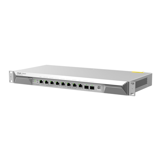
Hardware Installation and Reference Guide Product Introduction Appearance Figure 1-1 Appearance of RG-EG1510XS Figure 1-2 Front Panel of RG-EG1510XS Table 1-3 LEDs, Buttons and Ports Mark Item Description Indicates the working status of the hard disk drive. SATA LED Solid green: The hard disk drive is in place. Blinking green: A read/write operation is performed. - Page 10 Hardware Installation and Reference Guide Product Introduction Mark Item Description Indicates the working status of the system. Off: The system is powered off. Fast blinking green (8 blinks per second): The system is starting System LED Solid green: The system is operating normally. Slow blinking green (1 blink every two seconds): The system is not connected to the cloud.
- Page 11 Hardware Installation and Reference Guide Product Introduction Figure 1-3 Back Panel of RG-EG1510XS Table 1-4 LEDs, Buttons and Ports Mark Item Description Three-pin AC power cord connector Connects the power cord to supply power to the device. Power cord retainer clip hole Holds the power cord retainer clip.
-
Page 12: Technical Specifications
Hardware Installation and Reference Guide Product Introduction Table 1-5 Label of RG-EG1510XS Mark Item Description Label Contains the product name, model, I/O parameters, default IP address, etc. Technical Specifications Table 1-6 Technical Specifications Model RG-EG1510XS Quad-core processor, 1.8 GHz clock rate Flash Memory 128 MB eMMC... - Page 13 Hardware Installation and Reference Guide Product Introduction AC input: Rated voltage range: 100 V AC to 240 V AC Max. voltage range: 90 V AC to 264 V AC Power Supply Frequency: 50 Hz to 60 Hz Rated current: 1.5 A Power cord: 10 A power cord ≤...
-
Page 14: Preparing For Installation
Hardware Installation and Reference Guide Preparing for Installation Preparing for Installation Safety Precautions Note The devices mentioned in this manual cannot be mounted to a wall. To avoid personal injury and device damage, carefully read the safety precautions before you install the device. -
Page 15: Electrostatic Discharge Safety
Hardware Installation and Reference Guide Preparing for Installation If a power supply system is equipped with a leakage protector (also referred to as “leakage current switch” or “leakage current breaker”), the power supply will be cut off automatically when the electric leakage or electric shock occurs. -
Page 16: Installation Environment Requirements
Hardware Installation and Reference Guide Preparing for Installation There is the potential risk of fire or explosion or device damage if the battery of an incorrect type is replaced. Replace the battery only with the same type. Disposal of a battery into fire or a hot oven, or mechanically crushing or cutting of a battery, can result in an explosion. -
Page 17: Temperature/Humidity Requirements
Hardware Installation and Reference Guide Preparing for Installation 2.2.4 Temperature/Humidity Requirements To ensure the normal operation and prolonged service life of the device, maintain an appropriate temperature and humidity in the equipment room. The equipment room with too high or too low temperature and humidity for a long period may damage the device. ... -
Page 18: Grounding Requirements
Hardware Installation and Reference Guide Preparing for Installation Table 2-3 Requirements for Gases Average (mg/m Maximum (mg/m Sulfur dioxide (SO Hydrogen sulfide Nitrogen dioxide (NO Chlorine gas (CI Note Average refers to the average value of harmful gases measured in one week. Maximum refers to the upper limit of harmful gases measured in one week, and the maximum value lasts up to 30 minutes every day. -
Page 19: Anti-Interference Requirements
Hardware Installation and Reference Guide Preparing for Installation 2.2.7 Anti-interference Requirements Various interference sources, from either outside or inside the equipment or application system, affect the device in the conductive ways such as capacitive coupling, inductive coupling, and electromagnetic radiation. There are two types of electromagnetic interferences: radiated interference and conducted interference, depending on the type of the propagation path. -
Page 20: Notes For Connecting Optical Cables
Hardware Installation and Reference Guide Preparing for Installation Figure 2-1 Standard 19-inch Cabinet (3) The distance between the square hole strip on the rack column and the outer side of the front cabinet door is greater than 180 mm (7.09 in.) and the thickness of the front cabinet door is smaller than 25 mm (0.98 in.). Therefore, the available space is greater than 155 mm (6.10 in.). - Page 21 Hardware Installation and Reference Guide Preparing for Installation Note The device is delivered without a tool kit. Please prepare a tool kit yourself.
-
Page 22: Installing The Router
Hardware Installation and Reference Guide Installing the Router Installing the Router Caution Ensure that requirements in Chapter 2 are all met. Installation Procedure The installation steps are shown in the following figure. Table 3-1 Installation Procedure Prepare for installation Read precautions Install the device Ground the device Connect the power supply... -
Page 23: Before You Begin
Hardware Installation and Reference Guide Installing the Router Before You Begin Carefully plan and arrange the installation position, networking mode, power supply and cabling before installation. Confirm the following requirements before installation: The installation site provides sufficient space for heat dissipation. ... -
Page 24: Precautions
Hardware Installation and Reference Guide Installing the Router (3) Tighten the screws. Precautions To ensure the normal operation and prolonged service life of the device, please observe the following precautions: Do not power on the device during installation. Install the device in a well-ventilated position. -
Page 25: Installing The Device
Hardware Installation and Reference Guide Installing the Router Installing the Device Mounting the Device into a Cabinet 3.5.1 1. Precautions If you want to install the RG-EG1510XS router into a cabinet, mount the cabinet first. When mounting the cabinet, please note the followings: ... -
Page 26: Mounting The Device On A Workbench
Hardware Installation and Reference Guide Installing the Router Figure 3-1 Securing the Mounting Brackets (2) Mount the device into the cabinet and secure the other end of the brackets to square hole posts of the cabinet using the cage nuts and M6 screws 3.5.2 Mounting the Device on a Workbench If a standard 19-inch cabinet is unavailable, you can mount the device on a workbench. -
Page 27: Connecting Cables
Hardware Installation and Reference Guide Installing the Router well grounded in the building. In general, the power supply neutral point of the building has been buried in the ground during the cabling. Users need to confirm whether the power supply of the building has been properly grounded. -
Page 28: Verifying Installation
Hardware Installation and Reference Guide Installing the Router 3.10 Verifying Installation 3.10.1 Verifying the Device Verify if the external power supply matches with the distribution panel of the cabinet. Verify if the front/back cabinet doors can be closed after the device is installed. ... -
Page 29: Verifying Operating Status
Wireless Connection: Connect the access point to the LAN port of the router with an Ethernet cable. The access point will automatically broadcast SSID “@Ruijie-mXXXX” (XXXX are the last four characters of the MAC address on the device label.) after power-on. Perform configuration on the device after the PC is connected to the wireless network. -
Page 30: Log In To The Web Interface
Hardware Installation and Reference Guide Verifying Operating Status Log In to the Web Interface (1) Start up the PC and configure the local connection attribute on the PC. Change the static IP address of the PC to 192.168.110.XXX (1–255, excluding 1). Figure 4-2 Change the IP Address of the PC (2) Open a browser, enter 192.168.110.1 into the address bar of the browser, and press Enter. -
Page 31: Troubleshooting
Check the device installation Check the power connection Check the LEDs on the device Check the cable connection Contact Technical Support of Ruijie Networks Common Troubleshooting Procedures 5.2.1 Password Loss Press the Reset button for more than 5 seconds to restore the device to factory default settings and reset the system login password. -
Page 32: Appendix
Hardware Installation and Reference Guide Appendix Appendix Connectors and Media 2500BASE-T/1000BASE-T/100BASE-TX/10BASE-T The 2500BASE-T/1000BASE-T/100BASE-TX/10BASE-T is a 10/100/1000/2500 Mbps adaptive port that supports auto MDI/MDIX Crossover. Compliant with IEEE 802.3bz, 2500BASE-T requires Category 5e 100-ohm UTP or STP (STP is recommended) with a maximum distance of 100 meters (328 feet). -
Page 33: Mini-Gbic And 10Ge Sfp+ Module Specifications
SFP modules (mini-GBIC module) and 10GE SFP+ modules are available to cope with interface types of switch modules. You can select the mini-GBIC module to suit your specific needs. The models and technical specifications of some mini-GBIC and 10GE SFP+ modules are listed below. For details, see Ruijie module Installation and Reference Guide. - Page 34 Hardware Installation and Reference Guide Appendix Intensity of Intensity of Transmitted Received Light Wave Length Media Model Light (dBm) (dBm) (nm) Type (Yes/No) GE-SFP-LX20-SM1550- 1550TX/1310 BIDI GE-SFP-LH40-SM1310- 1310TX/1550 BIDI GE-SFP-LH40-SM1550- 1550TX/1310 BIDI MINI-GBIC-ZX80- 1550 SM1550 MINI-GBIC-ZX100- 1550 SM1550 SFP-MM850 -9.5 SFP-SM1310 1310 -9.5...
- Page 35 Hardware Installation and Reference Guide Appendix SFP Model Interface Type Fiber Type Core Size(μm) Cabling Distance MINI-GBIC-LH40-SM1310 9/125 40 km GE-SFP-SX-SM1310-BIDI 50/125 500 m GE-SFP-SX-SM1550-BIDI 50/125 500 m GE-SFP-LX20-SM1310-BIDI 9/125 20 km GE-SFP-LX20-SM1550-BIDI 9/125 20 km GE-SFP-LH40-SM1310-BIDI 9/125 40 km GE-SFP-LH40-SM1550-BIDI 9/125 40 km...
- Page 36 Hardware Installation and Reference Guide Appendix Table 6-5 Specifications of SFP BIDI Optical Module Pairs Rate/Distance Module Pairs GE-SFP-SX-SM1310-BIDI 1000 Mbps/500 m GE-SFP-SX-SM1550-BIDI GE-SFP-LX20-SM1310-BIDI 1000 Mbps/20 km GE-SFP-LX20-SM1550-BIDI GE-SFP-LH40-SM1310-BIDI 1000 Mbps/40 km GE-SFP-LH40-SM1550-BIDI XG-SFP-LR-SM1270-BIDI 10GE/10 km XG-SFP-LR-SM1330-BIDI Caution The BIDI modules must be used in pairs, for example, FE-SFP-LX20-SM1310-BIDI and FE-SFP-LX20- SM1550-BIDI are used together.
- Page 37 Hardware Installation and Reference Guide Appendix Transmit (dBm) Receive (dBm) Wavelength Model Fiber Type (nm) (Yes/No) XG-eSFP-LR- 1310 -8.2 -14.4 SM1310 XG-SFP-ER- 1550 -4.7 -11.3 SM1550 XG-SFP-ZR- 1550 SM1550 SFP-S4- 1310 -8.2 -14.4 R1000P1 v2 SFP-S1- 1310 -8.2 -14.4 R1000P1 SFP+1310 1310 -8.2...
- Page 38 Note The types/models of the SFP+ modules are being updated. If more accurate models of the module are required, contact Ruijie marketing staff or technical support engineers. The TX power of AOC cable can be displayed as “N/A”. Table 6-8...
-
Page 39: Cabling Recommendations
Hardware Installation and Reference Guide Appendix Interface Fiber Modal Bandwidth Cabling Model Core Size(μm) Type Type (MHz.km) Distance XG-SFP-SR-MM850-I 50/125 2000(OM3) 300 m XG-SFP-LR-SM1310-I 9/125 10 km Cabling Recommendations When RG-EG1510XS router is installed in standard 19-inch cabinets, cables are tied in the binding rack on the cabinet by the cabling rack, and top or bottom cabling is adopted according to the actual situation in the equipment room. - Page 40 Hardware Installation and Reference Guide Appendix Figure 6-4 Bundling Cables (1) Cables of different types (such as power cords, signal cables, and ground cables) should be separated in cabling and bundling. When they are close, crossover cabling can be adopted. In the case of parallel cabling, maintain a space of at least 30 mm (1.18 in.) for power cords and signal cables.
- Page 41 Hardware Installation and Reference Guide Appendix Figure 6-6 Bundling Cables (3) Cables not to be assembled or remaining parts of cables should be folded and placed in a proper position of the cabinet or cabling slot. The proper position will not affect device running or cause device or cable damage during commissioning.
- Page 42 Hardware Installation and Reference Guide Appendix Do not use self-tapping screws to fasten terminals. Power cables of the same type in the same cabling direction should be bundled up into cable bunches, with clean and straight cables in cable bunches. ...
Need help?
Do you have a question about the Reyee RG-EG1510XS and is the answer not in the manual?
Questions and answers