
Related Manuals for Ruijie Reyee RG-EG209GS


Summary of Contents for Ruijie Reyee RG-EG209GS
- Page 1 Ruijie Reyee RG-EG209GS Router Hardware Installation and Reference Guide Document Version: V1.0 Date: 2022.4.7 Copyright © 2022 Ruijie Networks...
- Page 2 Due to product version upgrades or other reasons, the content of this document will be updated from time to time. Ruijie Networks reserves the right to modify the content of the document without any notice or prompt. This manual is for reference only. Ruijie Networks endeavors to ensure content accuracy and will not shoulder...
-
Page 3: Preface
Intended Audience This document is intended for: Network engineers Technical support and servicing engineers Network administrators Technical Support The official website of Ruijie Reyee: https://www.ruijienetworks.com/products/reyee Technical Support Website: https://www.ruijienetworks.com/support Case Portal: https://caseportal.ruijienetworks.com Community: https://community.ruijienetworks.com... - Page 4 Note This manual provides the device installation steps, hardware troubleshooting, module technical specifications, and specifications and usage guidelines for cables and connectors. It is intended for the users who have some experience in installing and maintaining network hardware. At the same time, it is assumed that the users are already familiar with the related terms and concepts.
-
Page 5: Table Of Contents
Contents Preface ..............................I 1 Product Overview ..........................1 1.1 RG-EG209GS ..........................1 1.2 Package Contents........................1 1.2.1 RG-EG209GS ........................ 1 1.3 Product Appearance ........................2 1.3.1 RG-EG209GS ........................ 2 1.4 Technical Specifications ......................3 1.4.1 RG-EG209GS ........................ 3 2 Preparing for Installation ........................6 2.1 Safety Precautions ........................ - Page 6 2.2.8 Lightning Protection Requirements ................10 2.2.9 Installation Site Requirements ..................11 2.3 Tools ............................11 3 Installing the Router ........................12 3.1 Installation Procedure ......................12 3.2 Preparing..........................13 3.3 Precautions ..........................13 3.4 Installing the Device ......................... 13 3.4.1 Mounting the Device on a Workbench .................
- Page 7 5 Troubleshooting ..........................19 5.1 General Troubleshooting Procedure ..................19 5.2 Common Troubleshooting Procedures ..................19 5.2.1 Password Loss ......................19 5.2.2 System LED Error ......................19 6 Appendix ............................20 6.1 Connectors and Media ......................20 6.2 Fiber-Optic Cable Connection ....................21 6.3 Mini-GBIC and SFP Modules....................
-
Page 8: Product Overview
Product Overview RG-EG209GS The RG-EG209GS series routers are independently developed by Ruijie Networks with independent intellectual property rights. RG-EG209GS routers are a new generation of products for the small and micro enterprise offices, small hotels, and villas, providing 600Mbps of egress bandwidth to meet the user need of high-speed bandwidth. -
Page 9: Product Appearance
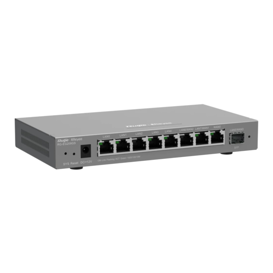
Hardware Installation and Reference Guide Product Overview Product Appearance 1.3.1 RG-EG209GS Figure 1-1 RG-EG209GS Router Appearance Figure 1-2 Front Panel of an RG-EG209GS Router Table 1-3 Front Panel Specifications Item Description System Status LED See Table 1-4 for details. Press for less than 2 seconds to reboot the router. Press for more than 5 seconds until the system LED flashes to restore the Reset Button router to factory default settings. -
Page 10: Technical Specifications
Hardware Installation and Reference Guide Product Overview Item Description Solid green: The port has made a successful link. Link/ACT Port LED Blinking green: The port is transmitting or receiving traffic. 10/100/1000BASE-T Ethernet RJ45 with auto negotiation. The port is switchable LAN/WAN Switchable Port between the WAN port and the LAN port. - Page 11 Hardware Installation and Reference Guide Product Overview Flash Memory 32 MB SDRAM DDRIII 256 MB Eight 10/100/1000BASE-T Ethernet RJ45 with auto negotiation and one Fixed Service Ports 1000Base-X SFP port, including eight LAN ports and one WAN port. Three LAN ports can be switched to the WAN port.
- Page 12 Dimensions (W x D x H) 202 mm x 108 mm x 28 mm (7.95 in. x 4.25 in. x 1.10 in.) Weight 0.55 kg (1.21 lbs) Caution Please use the power adapter delivered with the router by Ruijie Networks.
-
Page 13: Preparing For Installation
Hardware Installation and Reference Guide Preparing for Installation Preparing for Installation Safety Precautions Note To avoid personal injury and device damage, carefully read the safety precautions before you install the device. The following safety precautions may not cover all possible dangers. 2.1.1 General Safety Precautions ... -
Page 14: Electrostatic Discharge Safety
Hardware Installation and Reference Guide Preparing for Installation electric shock occurs. The selected leakage protector should comply with the following rule: ○ The rated leakage action current of each leakage protector is greater than twice of the theoretical maximum leakage current of all the power supplies in the system. For example, if a system is equipped with 16 identical power supplies, the leakage current of each power supply is equal to or less than 3.5 mA, and the leakage current of the system totals 56 mA. -
Page 15: Ventilation Requirements
Hardware Installation and Reference Guide Preparing for Installation 2.2.2 Ventilation Requirements Maintain a minimum clearance of 100 mm (3.94 in.) around the device for air circulation and normal heat dissipation. After various cables are connected, bundle the cables or place them in the cable management bracket to avoid blocking air inlets. -
Page 16: Grounding Requirements
Hardware Installation and Reference Guide Preparing for Installation Table 2-2 Requirements for Dust Dust Unit Content Dust particles (diameter ≥ 0.5 μm) ≤ 3.5×10 Particles/m Dust particles (diameter ≥ 5 μm) ≤ 3.5×10 Particles/m Apart from dust, the salt, acid, and sulfide in the air in the equipment room must meet strict requirements. These harmful substances will accelerate metal corrosion and component aging. -
Page 17: Anti-Interference Requirements
Hardware Installation and Reference Guide Preparing for Installation Lightning Grounding The lightning protection system of facilities is standalone, and is composed of a lightning rod, a lower conductor, and a connector connected to the grounding system. The grounding system is usually used for power reference grounding and safety grounding of the cabinet. -
Page 18: Installation Site Requirements
Hardware Installation and Reference Guide Preparing for Installation 2.2.9 Installation Site Requirements Regardless of whether the device is installed into a cabinet or on a workbench, the following conditions must be met: Maintain a proper clearance around the air vents for heat dissipation. ... -
Page 19: Installing The Router
Hardware Installation and Reference Guide Installing the Router Installing the Router Caution Ensure that requirements in Chapter 2 are all met. Installation Procedure The installation steps are shown in the following figure. Figure 3-1 Installation Procedure Prepare for installation Read precautions Install the device Ground the device Connect the power supply... -
Page 20: Preparing
Hardware Installation and Reference Guide Installing the Router Preparing Carefully plan and arrange the installation position, networking mode, power supply and cabling before installation. Confirm the following requirements before installation: The installation site provides sufficient space for heat dissipation. ... -
Page 21: Connecting The Ground Cable Of The Device
Hardware Installation and Reference Guide Installing the Router 3.4.2 Mounting the Device on the Wall RG-EG209GS can be mounted on the wall. (Mounting screws and wall anchors are customer-supplied.) In actual installation, users need to determine the size and depth of the two mounting holes on the wall based on the sizes of wall anchors and screws. -
Page 22: Connecting The Power Supply
Hardware Installation and Reference Guide Installing the Router Precautions: The cross-sectional area of the ground cable should be determined according to the possible maximum current. Cables with good conductor should be used. Do not use bare wires. The resistance between the chassis and ground should be less than 1 ohm. -
Page 23: Bundling Steps
Hardware Installation and Reference Guide Installing the Router Do not bundle twisted pairs and fiber-optic cables too tightly, as this may press hard the fibers and affect their service life and transmission performance. 3.8.2 Bundling Steps (1) Bind the drooping part of the twisted pairs and fiber-optic cables and lead them to both sides of the device for convenience. -
Page 24: Verifying Operating Status
Wireless Connection: Connect the access point to the LAN port of the router with an Ethernet cable. The access point will automatically broadcast SSID “@Ruijie-mXXXX” (XXXX are the last four characters of the MAC address on the device label.) after power-on. Perform configuration on the device after the PC is connected to the wireless network. -
Page 25: Configuring The Router
Hardware Installation and Reference Guide Verifying Operating Status Configuring the Router You can perform specific configuration on the device as required. For details, please refer to the related user manual. -
Page 26: Troubleshooting
Check the device installation Check the power connection Check the LEDs on the device Check the cable connection Contact Technical Support of Ruijie Networks Common Troubleshooting Procedures 5.2.1 Password Loss Press the Reset button for more than 5 seconds to restore the device to factory default settings and reset the system login password. -
Page 27: Appendix
Hardware Installation and Reference Guide Appendix Appendix Connectors and Media 1000BASE-T/100BASE-TX/10BASE-T The 1000BASE-T/100BASE-TX/10BASE-T is a 10/100/1000 Mbps adaptive port that supports auto MDI/MDIX Crossover. Compliant with IEEE 802.3ab, 1000BASE-T requires Category 5e 100-ohm UTP or STP (STP is recommended) with a maximum distance of 100 meters (328 feet). -
Page 28: Fiber-Optic Cable Connection
Hardware Installation and Reference Guide Appendix Figure 6-2 100BASE-TX/10BASE-T Twisted Pair Connection Fiber-Optic Cable Connection Please choose SMF or MMF optic cables according to the module types. Figure 6-3 Fiber-Optic Cable Connection... -
Page 29: Mini-Gbic And Sfp Modules
Apart from the following GE SFP modules, Mini-GBIC-GT modules are also provided for selection. The following models and technical specifications of some GE SFP modules are listed for your reference. For details, see Ruijie Transceiver Installation and Reference Guide. Table 6-2... - Page 30 Hardware Installation and Reference Guide Appendix Table 6-3 Copper GE SFP Transceiver Module Model 1000Base-T SFP Transceiver Module Standard Support DDM(Yes/No) Model 1000Base-T Mini-GBIC-GT Table 6-4 SFP Transceiver Module Cabling Specifications Max Cable GBIC/SFP Module Model Connector Fiber Type Core Size (um) Distance 62.5/125 275 m...
-
Page 31: Cabling
Hardware Installation and Reference Guide Appendix Caution For fiber modules with a cable distance of more than or equal to 40 km (24.85 miles), insert an on-line optical attenuator in the link to avoid the optical receiver overload if the short-distance single mode fiber (SMF) is adopted. -
Page 32: Requirements For The Minimum Cable Bend Radius
Hardware Installation and Reference Guide Appendix equipment room. All transferred cable connectors should be placed at the bottom of the cabinet in an orderly manner instead of outside the cabinet that is easy to touch. Power cords are routed beside the cabinet, and top cabling or bottom cabling is adopted according to the actual situation in the equipment room, such as the positions of the DC power distribution box, AC socket, or lightning protection box. - Page 33 Hardware Installation and Reference Guide Appendix sharp corners. Figure 6-5 Binding Cables (2) When cables need to be bent, please bundle them up but do not tie them where the cables will be bent. Otherwise, considerable stress may be generated in cables, breaking cable cores. Figure 6-6 Binding Cables (3) ...
- Page 34 Hardware Installation and Reference Guide Appendix When screw threads are used to fasten cable terminals, the bolt or screw must be tightly fastened, and anti- loosening measures should be taken. Figure 6-7 Cable Fastening Table 6-6 Cable Fastening Components Components Flat washer Spring washer...
- Page 35 Hardware Installation and Reference Guide Appendix For wiring terminal blocks (such as circuit breakers) with cord end terminals, the metal part of the cord end terminal should not be exposed outside the terminal block when assembled.
Need help?
Do you have a question about the Reyee RG-EG209GS and is the answer not in the manual?
Questions and answers