Advertisement
- 1 FEATURES
- 2 PRODUCT REGISTRATION
- 3 IMPORTANT SAFETY WARNINGS
- 4 INSTALLING YOUR DEVICE
- 5 DEFINITIONS FOR ILLUMINATED LCD INDICATORS
- 6 TECHNICAL SPECIFICATIONS
- 7 TROUBLESHOOTING
- 8 SYSTEM BLOCK DIAGRAM
- 9 CYBERPOWER GREENPOWER UPS TECHNOLOGY
- 10 LIMITED WARRANTY AND CONNECTED EQUIPMENT GUARANTEE
- 11 Documents / Resources
FEATURES

- Power Switch
- Power On Indicator
- LCD module display
- Display/Select button
- Battery backup and Surge Protected Outlets
- Full-Time Surge Protected Outlets
- Circuit Breaker
- USB Ports to PC
- Wiring Fault Indicator (red)
- Widely Spaced Outlets Designed for AC Adapters
PRODUCT REGISTRATION
Thank you for purchasing a CyberPower product. Please take a few minutes to register your product at www.cyberpowersystems.com/registration/. Registration certifies your product's warranty, confirms your ownership in the event of a product loss or theft and entitles you to free technical support. Register your product now to receive the benefits of CyberPower ownership.
IMPORTANT SAFETY WARNINGS
(SAVE THESE INSTRUCTIONS)
This manual contains important safety instructions. Please read and follow all instructions carefully during installation and operation of the unit. Read this manual thoroughly before attempting to unpack, install, or operate your UPS.


To prevent the risk of fire or electric shock, install in a temperature and humidity controlled indoor area free of conductive contaminants. (Please see specifications for acceptable temperature and humidity range).
To reduce the risk of electric shock, do not remove the cover except to service the battery. Turn off and unplug the unit before servicing the batteries. There are no user serviceable parts inside except for the battery.

Hazardous live parts inside can be energized by the battery even when the AC input power is disconnected.
The UPS must be connected to an AC power outlet with fuse or circuit breaker protection. Do not plug into an outlet that is not grounded. If you need to de-energize this equipment, turn off and unplug the unit.
To avoid electric shock, turn off the unit and unplug it from the AC power source before servicing the battery or installing a computer component.
Not for use in a computer room as defined in the Standard for the Protection of Electronic Computer/Data Processing Equipment, ANSI/NFPA 75.

To reduce the risk of fire, connect only to a circuit provided with 20 amperes maximum branch circuit over current protection in accordance with the National Electric Code, ANSI/NFPA 70.
DO NOT USE FOR MEDICAL OR LIFE SUPPORT EQUIPMENT! DO NOT use in any circumstance that would affect the operation and safety of life support equipment, medical applications, or patient care.
DO NOT USE WITH OR NEAR AQUARIUMS! To reduce the risk of fire or electric shock, do not use with or near an aquarium. Condensation from the aquarium can cause the unit to short out.
DO NOT USE THE UPS ON ANY TRANSPORTATION! To reduce the risk of fire or electric shock, do not use the unit on any transportation such as airplanes or ships. The effect of shock or vibration caused during transit and the damp environment can cause the unit to short out.
INSTALLING YOUR DEVICE
UNPACKING
Inspect the UPS upon receipt. The box should contain the following:
- UPS unit
- User's manual
- USB A+B type cable
- Function Setup Guide
*PowerPanel Personal software is available on our website. Please visit www.CyberPowerSystems.com and go to the Software Section for free download.
OVERVIEW
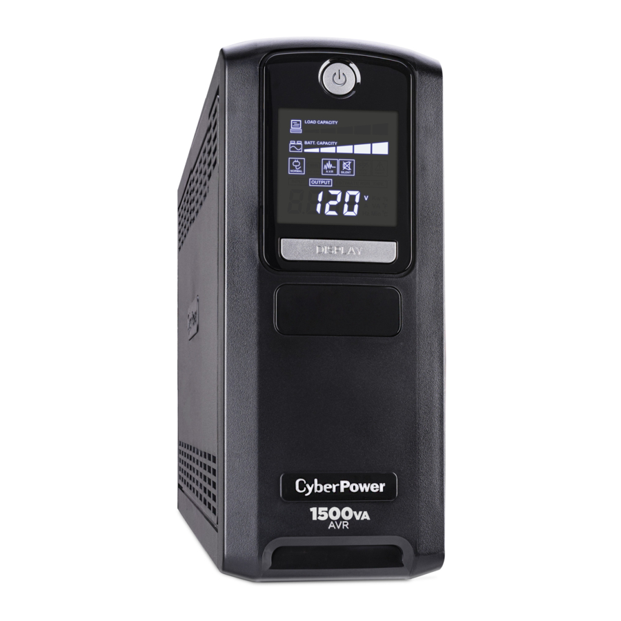
The LX1500GAVR provides complete power protection from utility power that is not always consistent. The LX1500GAVR features 890 Joules of surge protection. The unit provides long lasting battery backup during power outages with maintenance free batteries. The LX1500GAVR ensures consistent power to your computer system and includes software that will automatically save your open files and shutdown your computer system during a utility power loss.
AUTOMATIC VOLTAGE REGULATOR
The LX1500GAVR uses Automatic Voltage Regulation (AVR) to stabilize inconsistent utility power voltage to levels that are safe for connected equipment. AVR safeguards hardware and important data files by automatically increasing low utility power to a consistent and safe output voltage while preserving battery power for outages.
DETERMINE THE POWER REQUIREMENTS OF YOUR EQUIPMENT
- Ensure that the equipment plugged into the outlet does not exceed the UPS's rated capacity 1500VA/900W for LX1500GAVR. If the rated capacity of the unit is exceeded, an overload condition may occur and cause the UPS to shut down or the circuit breaker to trip.
- There are many factors that can affect the amount of power that your computer system will require. It is suggested that the load placed on the battery outlets not exceed 80% of the unit's capacity.
REPLACING THE BATTERY
Replacement of batteries located in an OPERATOR ACCESS AREA.
- When replacing batteries, replace with the same number of the following battery: CyberPower / RB1270X2C for the LX1500GVAR.
![]()
Risk of Energy Hazard, 24 V, maximum 9 Ampere-hour battery. Before replacing batteries, remove conductive jewelry such as chains, wrist watches, and rings. High energy conducted through these materials could cause severe burns.![]()
Do not dispose of batteries in a fire. The batteries may explode.![]()
Do not open or mutilate batteries. Released material is harmful to the skin and eyes. It may be toxic.![]()
A battery can present a risk of electrical shock and high short circuit current. The following precautions should be observed when working on batteries:- Remove watches rings, or other metal objects.
- Use tools with insulated handles.
RISK OF EXPLOSION IF BATTERY IS REPLACED BY AN INCORRECT TYPE.
DISPOSE OF USED BATTERIES ACCORDING TO LOCAL REGULATIONS.
BATTERY REPLACEMENT PROCEDURE:
- Switch off and unplug all the connected equipment.
![]()
- Switch off the UPS and disconnect it from the wall outlet.
![]()
- Place the product on its side, on a solid and stable surface.
![]()
- Loosen the battery compartment cover screws.
![]()
- Press on the locking latch and slide the battery compartment cover.
![]()
- Disconnect the battery wires from the right side of the battery and then take it out of the battery compartment.
![]()
- Disconnect the battery wires from the remaining battery.
![]()
- Slide the remaining battery from left to right and remove it from the compartment.
![]()
- Install the "left side" replacement battery by connecting the yellow wire (+) to the red connector from the battery and the black wire (-) to the black connector from the battery. Place the battery into the left side of the compartment.
- Install the "right side" replacement battery by connecting the red wire (+) to the red connector from the battery and yellow wire (-) to the black connector from the battery. Place the battery into the right side of the compartment. Note: Only new batteries should be used for replacement and both batteries should be replaced at the same time to ensure maximum life span.
- Close the battery compartment cover and secure it with the screws.
- Recharge the UPS for 8-16 hours to fully charge the battery.


REMINDER: Batteries are considered HAZARDOUS WASTE and must be disposed of properly. Most retailers that sell lead-acid batteries collect used batteries for recycling, as required by local regulations.
DEFINITIONS FOR ILLUMINATED LCD INDICATORS

- INPUT voltage meter: This meter measures the AC voltage that the UPS system is receiving from the utility wall outlet. The UPS is designed, through the use of automatic voltage regulation, to continuously correct output voltage to connected equipment to a safe 110/120 voltage output range. In the event of a complete power loss, severe sag, or over-voltage, the UPS relies on its internal battery to supply consistent 110/120 output voltage. The INPUT voltage meter can be used as a diagnostic tool to identify poor-quality input power.
- OUTPUT voltage meter: This meter measures, in real time, the AC voltage that the UPS system is providing to the computer, such as normal line mode, AVR mode, and battery backup mode. (Note: The OUTPUT voltage meter shows the status of the battery backup outlets.)
- ESTIMATED RUNTIME: This displays the run time estimate of the UPS with current battery capacity and load.
- NORMAL icon: This icon appears when the UPS is working under normal conditions.
- BATTERY icon: During a severe sag or power outage, this icon appears and an alarm sounds (two short beeps followed by a pause) to indicate the UPS is operating from its internal batteries. During a prolonged sag or power outage, the alarm will sound continuously to indicate the UPS's batteries are nearly out of power. You should save fles and turn of your equipment immediately or allow the software to shut the system down.
- AVR (Automatic Voltage Regulation) icon: This icon appears whenever your UPS is automatically correcting low AC line voltage without using battery power. This is a normal, automatic operation of your UPS, and no action is required on your part.
- SILENT MODE icon: This icon appears whenever the UPS is in silent mode. The buzzer does not beep during silent mode until the battery reaches low capacity.
- OVER LOAD icon: This icon appears and an alarm sounds to indicate the batterysupplied outlets are overloaded. To clear the overload, unplug some of your equipment from the battery-supplied outlets until the icon turns of and the alarm stops.
- FAULT: This icon appears if there is a problem with the UPS. Press the POWER button to turn the UPS of.
E02: Charger Fault-No Charge (Contact CyberPower Systems for support.)
E11: Battery Overvoltage (Contact CyberPower Systems for support.)
E21: Output Short (Check the status of equipment connected to the UPS and then turn on the UPS again.)
E22: Overload (Unplug at least one piece of equipment from battery outlets and turn the UPS on again.) - BATT. CAPACITY meter: This meter displays the approximate charge level (in 20% increments) of the UPS's internal battery. During a power outage or extended sag, the UPS switches to battery power, the BATTERY icon appears, and the charge level decreases.
- LOAD CAPACITY meter: This meter displays the approximate output load level (in 20% increments) of the UPS battery outlets.
For more information about functions setup, please refer to the Function Setup Guide.
TECHNICAL SPECIFICATIONS
| Model | LX1500GAVR |
| Capacity | 1500VA / 900W |
| Nominal Input Voltage | 120V |
| Input Frequency | 60 Hz ± 3 Hz |
| On-Battery Output Voltage | 120Vac ± 5% |
| Max. Load for UPS Outlets (5 Outlets) | 1500VA / 900W |
| Max. Load for Full-Time Surge Protection outlets (10 Outlets) | 12 Amp |
| On-Battery Output Wave Form | Simulated Sine Wave |
| Operating Temperature | + 32°F to 104°F / 0°C to 40°C |
| Operating Relative Humidity | 0 to 90% non-condensing |
| Size (W x H x D) | 3.9" x 9.8" x 13.7" (99 x 249 x 348 mm) |
| Net Weight | 21.8lbs/9.9kg |
| Battery Type | Sealed Maintenance Free Lead Acid Battery |
| Typical Battery Recharge Time | 8 hours to 90% from total discharge under 100% load |
| Typical Battery Life | 3 to 6 years, depending on number of discharge/recharge cycles |
| Recommended Battery | CyberPower / RB1270X2C |
| Safety Approvals | UL1778 (UPS), CSA C22.2 No. 107, FCC/DoC Class B |
TROUBLESHOOTING
| Problem | Possible Cause | Solution |
| Circuit breaker button is projecting from the back of the unit. | Circuit breaker has tripped due to an overload. | Turn the UPS off and unplug at least one piece of equipment. Wait 10 seconds, reset the circuit breaker by depressing the button, and then turn the UPS on. |
The unit does not perform expected runtime | Battery not fully charged. | Recharge the battery by leaving the UPS plugged in. |
| Battery is worn out. | Contact CyberPower about replacement batteries. | |
The device will not turn on | The on/off switch is designed to prevent damage from rapidly turning it off and on. | Turn the UPS off. Wait 10 seconds and then turn the UPS on. |
| The unit is not connected to an AC outlet. | The unit must be connected to a 110/120V 60Hz outlet. | |
| The battery is worn out. | Contact CyberPower about replacement batteries. | |
| Mechanical problem. | Contact CyberPower. | |
PowerPanel Personal software is inactive (all icons are gray) | The USB / serial cable is not connected. | Connect the USB / serial cable to the UPS unit and an open USB / serial port on the back of the computer. |
| The USB / serial cable is connected to the wrong port. | Check the back of the computer for an additional USB / serial port. Move the cable to this port. | |
| The unit is not providing battery power. | Shutdown your computer and turn the UPS off. Wait 10 seconds and turn the UPS back on. This should reset the unit. |
Additional troubleshooting information can be found under "Support" at www.CyberPowerSystems.com.
SYSTEM BLOCK DIAGRAM

CYBERPOWER GREENPOWER UPS TECHNOLOGY
Advanced Energy-Saving Patented Bypass Technology
CyberPower's patented GreenPower UPS with Bypass Technology reduces UPS energy costs by up to 75% compared to conventional UPS models. Even when utility power is normal, conventional UPS models constantly pass power through a transformer. By contrast, under normal conditions the advanced circuitry of a GreenPower UPS bypasses the transformer. As a result, the power efficiency is significantly increased while decreasing waste heat, using less energy, and reducing energy costs. When an abnormal power condition occurs, the GreenPower UPS automatically runs power through its transformer to regulate voltage and provide "safe" power. Since utility power is normal over 88% of the time, the GreenPower UPS operates primarily in its efficient bypass mode.
The GreenPower UPS is also manufactured in accordance with the Restriction on Hazardous Substances (RoHS) directive making it one of the most environmentally-friendly on the market today.
LIMITED WARRANTY AND CONNECTED EQUIPMENT GUARANTEE
Please visit www.CyberPowerSystems.com for a copy of the Limited Warranty and Connected Equipment Guarantee.
Where Can I Get More Information?
The application of the United Nations Convention of Contracts for the International Sale of Goods is expressly excluded. CyberPower is the warrantor under this Limited Warranty.
For further information please feel free to contact CyberPower at:
Cyber Power Systems (USA), Inc.
4241 12th Ave E., STE 400, Shakopee, MN 55379;
Call us at (877) 297-6937; or
submit a web ticket online at cyberpowersystems.com/support.

This product can expose you to chemicals including bisphenol A (BPA) and styrene, which is known to the State of California to cause reproductive harm and cancer. For more information, go to www.P65Warnings.ca.gov.
Documents / Resources
References
![www.cyberpowersystems.com]() Registration | CyberPower
Registration | CyberPower![www.cyberpowersystems.com]() CyberPower UPS Systems, Battery Backup, PDUs, USB Surge Protectors
CyberPower UPS Systems, Battery Backup, PDUs, USB Surge Protectors![www.p65warnings.ca.gov]() http://www.p65warnings.ca.gov
http://www.p65warnings.ca.gov![cyberpowersystems.com]() Support | CyberPower
Support | CyberPower![cyberpowersystems.com]() CyberPower UPS Systems, Battery Backup, PDUs, USB Surge Protectors
CyberPower UPS Systems, Battery Backup, PDUs, USB Surge Protectors

Download manual
Here you can download full pdf version of manual, it may contain additional safety instructions, warranty information, FCC rules, etc.
Advertisement


Need help?
Do you have a question about the LX1500GAVR and is the answer not in the manual?
Questions and answers