Advertisement
Install power supply
NOTE: Please refer to your CPU/ Memory component's documentation for instructions. RGB fans may not be synced in the beginning of installation. To sync, hold the RGB button for 3 seconds to reset the playable modes.
- Remove thumbscrews from both sides of the Prodigy case. There are four on the window and two on the solid side panel. In order to install all devices, you will have to have access to the entire inside of the case.

- Grab the notch on the edge of the non-window panel. Pull towards the back to release. Gently remove the glass window by lifting it up. Place both panels to the side until done with the installation process.

- Install power supply in the spot indicated in the picture. Slide it in until the holes line up in the back.

- Make sure that the power supply is correctly installed, and that screw mount points are aligned (as seen in step 5).


NOTE: Touch an unpainted metal section of the chassis to discharge static electricity before handling PC components. An anti-static wrist strap should also be worn to further minimize the possibility of damage.
- Fasten screws to the back of the case. Keep a hand on the power supply to keep the holes aligned. It is recommended to install the power supply "upside-down" (fan pointing towards bottom of case) for better airflow.


Install motherboard
- Most of the mounting holes for the motherboard are already preinstalled, but there are extras just in case they are needed.
The standoff screws are the hexagonal screws that you can find in the screw bag provided.

- If your motherboard included an I/O shield, fit the shield in the provided hole on the back of the case until it clicks into place. Make sure that the holes on the shield match up with the I/O connectors on the motherboard.

- Align motherboard with standoffs and mount to case. Use the round screws found in the screw bag to secure the motherboard in place.


Install PCI components
- First, remove the PCI slot covers. Push on the cover at a diagonal angle. Wiggle the cover until it comes loose. Make sure that you remove the correct slot covers as once they are removed you cannot replace them. Make sure you unscrew and remove the tab so you can secure the cards.

- Read your PCI expansion card's documentation. Install PCI card into correct slot for your card type (x1, x16, etc.). Once the card is seated firmly, secure it with a screw in the appropriate hole. Put the tab back and secure it in place with the screw.


Install hard drives
- For 3.5" hard-disk drives, find the two types of screw and the rubber washer as shown below and place the washer to the left side hole. Secure with the non-thumb screw. Slide the drive into the drive bay as shown in step 3 then secure with the thumb screw.

- For 2.5" hard-disk drives, find the mounting screws as shown below. Secure the drive with these screws to the bays as seen in Step 3.

- Original placement of both 3.5" and 2.5" drive mounts are located in the below marked rectangles.


Fan installation and setup
- Three fans are already pre-installed in the case. However, should you need to reconnect them, you need to make sure each of the 4-pin Molex connectors are daisy-chained together as shown below. The one labeled "Isolated Interface" controls the LED pattern/color and needs to plug in directly to the power supply.

- In order to properly use the colorchanging LEDs on the fans, make sure that one of the male LEDSW connectors from the fans are plugged into the female LEDSW connector coming from the front panel as shown. Hold the RGB button for 3 seconds to reset the pattern.

- There is a magnetic filter that sits on the top that allows for easy cleaning. You can remove it by lifting it off and replacing it when it's done. Can be water washed if desired. The switch labeled "RGB" on the top can be pressed to change fan colors or turn them off.


Connect product leads to motherboard
- Locate the below front panel leads. Refer to your motherboard user's manual for placement schematics.

- Locate the below front panel leads, Your motherboard user's manual will provide schematics, The triangular markings
![]() on the leads indicate positive wires.
on the leads indicate positive wires.


 on the leads indicate positive wires.
Complete the installation
- With all components properly installed, gently return side panels to their original positions and replace all screws.
Congratulations! You have completed assembly of the Prodigy.
![]()

Parts placement
- There is room for up to three 120mm fans or a 360/240mm water cooling setup in the front. There is also room for two 120mm fans in the top, one 120mm fan in the rear, and one 120mm fans in the bottom (bottom fans installed using the long 1 1/4" screws that come in the bag). You can install up to two 3.5" hard drives and two 2.5" hard drives in the case as well. Supports video cards up to 350mm long. Supports ATX, Micro-ATX, and ITX motherboards.
Water Cooling Installation
- Secure the fans on radiator and fasten the radiator inside of the casing by screwing it from outside.
(Memory Ram Lower than 32mm)
![]()

Top Fan Installation

- Lift up the dust filter.
- Align md secure your 120mm fan with screws.
![]()

Front/Rear Fan Installation
- Align and secure your 120mm fan with screws.


Specifications
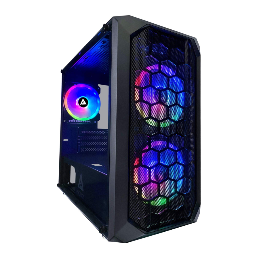
Modern Solid Steel ATX Mid Tower Computer Case
1 x Full Side Window for Max. Viewing
Simple Layout for Better Air Flow and Easy Maintenance
Well Cable Management: 7 x Holes for Cable Routing
Support Micro ATX / Mini ITX Motherboard
Support VGA up to 350mm in Length
Support CPU Cooler up to 162mm in Height
Support Standard ATX Motherboard Size up to 9.6" x 9.6"
Support Standard ATX Power Supply (Not Included)
Top Ports: 1 x USB 3.0, 2 x USB 2.0, 1 x HD Audio (Mic + Headphone), Fan Color Switch
Cooling Options:
- Front: 3 x 120mm Fan / or 2 x 140mm Fan / or 1 x 360/240mm Radiator
- Rear: 1 x 120mm Fan
- Top: 2 x 120mm Fan / or 1 x 240mm Radiator
- Bottom: 2 x 120mm Fan
3 x Superior 120mm RGB Case Fans Are Included (2 x Front, 1 x Rear,)
1 x Bottom Removable Dust Filter for Easy Cleaning
4 x Drive Bay: 2 x 3.5" (Internal) + 2 x 2.5" (Internal)
4 x Expansion Slots Power Supply (Not Included): Bottom Mounted
Material: Chassis-SECC Black Metal, Face Plate-ABS Plastic
Thumb Screws, Case Feet
Dimension: 16" x 8" x 15.5" (L x W x H)
Weight: 11.5 lbs
Documents / Resources
References

Download manual
Here you can download full pdf version of manual, it may contain additional safety instructions, warranty information, FCC rules, etc.
Advertisement


Need help?
Do you have a question about the Prodigy and is the answer not in the manual?
Questions and answers