Advertisement
Quick Links
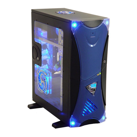
X-Navigator Installation Guide:
1.Install Motherboard, 3.5" & 5.25" Drives:
1.1.Remove two thumb screws
from the back of the side window.
Push the handle towards front
panel a bit, then pull it out.
1.4.Remove 3.5" HDD Cage.
Install 3.5" drives to the cage.
1.7.Remove the 5.25" bay covers.
Insert your index finger on the side,
push with pressure to the left and
and pull out as shown on the picture.
(All screws for MB, DVD, HDD and case keys are provided in Tool Box)
1.2.Install brass standoffs on the
right solid panel for MB.(Some
motherboards have different
layout. Please refer to MB manual.
1.5.Put the 3.5" HDD Cage
back in place.
1.8.Slide 5.25" drive into its bay.
1.3.Place your motherboard on
the brass standoffs. Screw in
your motherboard to standoffs
with motherboard screws.
1.6.Attach drive rails on both sides of
5.25" drives. (You can rails mounted
on the bottom of the case)
Advertisement

Related Manuals for Apevia X-Navigator


Summary of Contents for Apevia X-Navigator
- Page 1 X-Navigator Installation Guide: 1.Install Motherboard, 3.5” & 5.25” Drives: 1.1.Remove two thumb screws from the back of the side window. Push the handle towards front panel a bit, then pull it out. 1.4.Remove 3.5” HDD Cage. Install 3.5” drives to the cage.
- Page 2 2.Install Power Connection, LED’s and Front Panel Leads, USB and 1394 Firewire Cables: 2.1.Install 20-pin cable connector from power supply to motherboard. Please refer to MB manual 2.3.Connect 4-pin cable connectors from power supply to all 3.5” and 5.25” devices. 2.5.Connect LED’s and Front Panel Leads to MB -Power SW: Connect to MB “PWR”...
- Page 3 3.Install Fan Speed Controller, Fan Connectors, Front LED Lights, LCD and Temp. Sensors: 3.1.Find the two black-and-yellow cable connectors from front panel, one with INPUT CD 12V, the other with OUTPUT 0.3A 5 FAN MAX 1.2A. These two connectors are for Fan Speed Connector and fan connection 3.3.Linke all 5 fans(2*Back Fans, 1*Side Window Fan, 1*Front Fan, 1*Top Fan) together(Male to Female).
- Page 4 4.How to take out and insert Front Decorative Masks: 4.1.Take out the Front Decorative Masks: 4.1.1.Open the front door. Press down the upper clip and pull out the upper part 4.1.4.Pull out the upper Mask 4.2.3.Push down on the upper clip to fit into the hole.
- Page 5 X-Navigator Series USB/1394 cable pin assignment Cable USB 2.0 1394 Cable Color WHITE GREEN BLACK WHITE BLACK GREEN BROWN BLUE Function TPB- TPB+ TPA- TPA+...
Need help?
Do you have a question about the X-Navigator and is the answer not in the manual?
Questions and answers