
Related Manuals for Bunn VP17-1SS


Summary of Contents for Bunn VP17-1SS
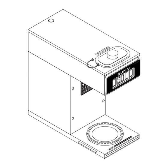
- Page 1 User Manual of Product 1: BUNN 13300.0001 VP17-1SS Pourover Coffee Brewer with 1-Warmer, Stainless Steel, Silver, Standard...
- Page 2 BUNN ® VP17A OPERATING & SERVICE MANUAL BUNN-O-MATIC CORPORATION POST OFFICE BOX 3227 SPRINGFIELD, ILLINOIS 62708-3227 PHONE: (217) 529-6601 FAX: (217) 529-6644 10860.0001C 9/00 ©1997 Bunn-O-Matic Corporation...
- Page 3 SPECIFIED HEREIN, TO REPAIR OR, AT BUNN’S SOLE OPTION, REPLACEMENT OR REFUND. In no event shall Bunn be liable for any other damage or loss, including, but not limited to, lost profits, lost sales, loss of use of equipment, claims of Buyer’s customers, cost of capital, cost of down time, cost of substitute equipment, facilities or services, or any other special, incidental or consequential damages.
- Page 4 USER NOTICES (cont.) # 00658.0000 #00831.0000 # 02763.0000 10860.1 091300 Page 3...
- Page 5 7. After water has stopped flowing from the funnel, let the water in the tank reheat to the proper temperature. 8. Empty the dispenser. The brewer is now ready for use in accordance with the coffee brewing instructions below. COFFEE BREWING 1. Insert a BUNN ® filter into the funnel.
- Page 6 CLEANING 1. The use of a damp cloth rinsed in any mild, non-abrasive, liquid detergent is recommended for cleaning all surfaces on Bunn-O-Matic equipment. 2. Check and clean the sprayhead. The sprayhead holes must always remain open. 3. With the sprayhead removed, insert the deliming spring (provided) all the way into the sprayhead tube. When inserted properly, no more than two inches of spring should be visible.
- Page 7 TROUBLESHOOTING A troubleshooting guide is provided to suggest probable causes and remedies for the most likely problems encountered. If the problem remains after exhausting the troubleshooting steps, contact the Bunn-O-Matic Technical Service Department. • Inspection, testing, and repair of electrical equipment should be performed only by qualified service personnel.
- Page 8 The dispenser must be completely empty before starting a brew cycle. Beverage overflows dispenser ® 1. Filter Type BUNN paper filters must be used for proper extraction. Weak beverage 2. Coffee Grind A fine or drip grind must be used for proper extraction.
- Page 9 TROUBLESHOOTING (cont.) PROBLEM PROBABLE CAUSE REMEDY Weak beverage (cont.) 4. Funnel Loading The BUNN ® paper filter must be centered in the funnel and the bed of grounds leveled by gentle shak- ing. 5. Water Temperature Place an empty funnel on an empty dispenser beneath the sprayhead.
-
Page 10: Table Of Contents
Contents SERVICE This section provides procedures for testing and Control Thermostat ..........10 replacing various major components used in this ON/OFF Warmer Switch ........11 brewer should service become necessary. Refer to Tank Heater ............12 Troubleshooting for assistance in determining the Thermal Cut-Offs .......... -
Page 11: Control Thermostat
SERVICE (cont.) 7. Voltage must not be present when the thermostat is turned to the "OFF" position. CONTROL THERMOSTAT If voltage is present as described, reinstall the capillary tube into the tank to the line 4.5" above the bulb, the control thermostat is operating properly. -
Page 12: On/Off Warmer Switch
SERVICE (cont.) If voltage is present as described, reconnect the red ON/OFF WARMER SWITCH wire and proceed to #5. If voltage is not present as described, refer to the Wiring Diagrams and check the brewer wiring har- ness. 5. With the black wire removed, remove the wire from the lower terminal. -
Page 13: Tank Heater
4. Remove sprayhead and the hex nut securing the SERVICE (cont.) sprayhead tube to the hood. Set aside for reas- TANK HEATER sembly. 5. Remove the eight #8-32 nuts securing the tank lid to the tank. 6. Remove the tank lid with sprayhead tube and tank heater. -
Page 14: Thermal Cut-Offs
SERVICE (cont.) Removal and Replacement: THERMAL CUT-OFFS 1. Disconnect the thermal cut-off from the terminal on the black lead from ready light harness and the black lead from the control thermostat or the tank heater terminal and the red lead from the main harness. -
Page 15: Warmer Elements
SERVICE (cont.) wire, and red/white, brown/black or violet wires on the WARMER ELEMENT(S) warmer element. If continuity is not present as described, replace the warmer element. Removal and Replacement: 1. Remove the three #4-40 screws securing the warmer assembly to the brewer. 2. -
Page 16: Wiring Diagrams
10860.1 091300 Page 15... - Page 17 10860.1 091300 Page 16...
- Page 18 10860.1 091300 Page 17...
Need help?
Do you have a question about the VP17-1SS and is the answer not in the manual?
Questions and answers