Advertisement
Quick Links
Introduction
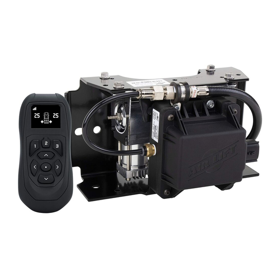
WirelessAIR™ EZ Mount™ combines a manifold and compressor into a single,
easy-to-install unit, along with wiring harness and accessories needed to connect to
vehicle power and air springs (purchased separately).
NOTATION EXPLANATION
Hazard notations highlight information that must be observed to help minimize risk of
personal injury or possible improper installation, which may render the vehicle unsafe.
INDICATES IMMEDIATE HAZARDS WHICH WILL RESULT IN SEVERE PERSONAL
DANGER
INJURY OR DEATH.
INDICATES HAZARDS OR UNSAFE PRACTICES WHICH COULD RESULT IN SEVERE
WARNING
PERSONAL INJURY OR DEATH.
INDICATES HAZARDS OR UNSAFE PRACTICES WHICH COULD RESULT IN DAMAGE
CAUTION
TO THE MACHINE OR MINOR PERSONAL INJURY.
TOOLS LIST
Description ................................................. Qty
Power drill .............................................................1
3/8" Drill bits ...................................................1 ea.
3/8", 1/2", 5/16", 9/16" Sockets & ratchet .....1 ea.
MN-1100 • (032208) • ECR 10025
IMPORTANT: PLEASE READ BEFORE INSTALLING
IT IS IMPORTANT TO READ AND UNDERSTAND THE ENTIRE INSTALLATION GUIDE
BEFORE BEGINNING INSTALLATION OR PERFORMING ANY MAINTENANCE,
SERVICE OR REPAIR. THE INFORMATION HERE INCLUDES A HARDWARE LIST,
STEP-BY-STEP INSTALLATION INFORMATION AND SAFETY INFORMATION.
USING THE SYSTEM
Refer to the WirelessAir™ User Guide included with this kit
to learn how to operate the system, connect the wireless
controller and connect your mobile device to the system.
Manifold
Kit Number
74000EZ
EZ Mount Compressor System
Installation Guide
WirelessAir User Guide
Compressor
Description ................................................. Qty
Wire stripping/crimping tool .................................1
Sharp razor knife ..................................................1
User Guide
1
Advertisement

Related Manuals for Air Lift Wireless AIR EZ Mount 74000EZ


Summary of Contents for Air Lift Wireless AIR EZ Mount 74000EZ
- Page 1 Kit Number 74000EZ EZ Mount Compressor System Installation Guide Introduction WirelessAIR™ EZ Mount™ combines a manifold and compressor into a single, easy-to-install unit, along with wiring harness and accessories needed to connect to vehicle power and air springs (purchased separately). IMPORTANT: PLEASE READ BEFORE INSTALLING IT IS IMPORTANT TO READ AND UNDERSTAND THE ENTIRE INSTALLATION GUIDE BEFORE BEGINNING INSTALLATION OR PERFORMING ANY MAINTENANCE,...
- Page 2 HARDWARE LIST Item Part # Description ....................Qty 73006 Wireless controller ....................1 26564 EZ Mount assembly ....................1 72710 Manifold .........................1 16192 Compressor ......................1 20946 Air line (1/4”) .......................25 ft. 26897 Wiring harness .......................1 Hardware Pack: 21838 Tee 1/4” PTC ......................2 24652 ATC fuse, spade 15A .....................1 24752...
- Page 3 Wiring to the battery CAUTION INSTALL THE FUSE AFTER ALL CONNECTIONS ARE MADE. OPTIONAL Ignition Source Connection Connect the pink wire to any wire that is active when the ignition is on. This will allow WirelessAIR to only make adjust- ments when the ignition is turned on.
- Page 4 Installing WirelessAir EZ Mount 1. There are three choices for mounting: • Hex cap bolts (N) with flat washers (M) and nylon lock nuts (L). • U-bolt (K) with washers (M) and nylon lock nuts (L). See Figure 3 for U-bolt installation.
- Page 6 DRILLING TEMPLATE VERIFICATION IMPORTANT: PRINT THIS CAUTION PAGE AT 100% SCALE. THIS IS A DRILLING TEMPLATE, WHICH WOULD BE RENDERED INCORRECT IN DIMENSION IF PRINTED WITH ANY SCALING. USING AN INCORRECT TEMPLATE TO DRILL HOLES MAY CAUSE DAMAGE TO THE VEHICLE! PLEASE REFER TO THE ONE-INCH OR 1CM SCALES AND USE A MEASURING...
- Page 7 7.00" [177.8 mm] 10.62" [269.7 mm] 8.20" [208.3 mm]...
- Page 9 5. Connect the wiring harness (D) to the manifold (Fig. 2). Press the connector on completely and listen for an audible “click.” Press white lock on connector toward manifold to lock connector in place. Ensure a proper drip loop exists to prevent water intrusion (Fig.
- Page 10 The minimum bend radius for 1/4” air line is 1” (25mm). Air lines are to be installed straight into fittings. Inspect the air line for scratches that run lengthwise. Contact Air Lift customer service if the air line is damaged. Good cut Bad cut fig.
-
Page 12: Need Help
For the latest version of this manual, contact Air Lift Company at (800) 248-0892 or visit www.airliftcompany.com. Air Lift Company • 2727 Snow Road • Lansing, MI 48917 or P.O. Box 80167 • Lansing, MI 48908-0167 Toll Free (800) 248-0892 • Local (517) 322-2144 • Fax (517) 322-0240 • www.airliftcompany.com...
Need help?
Do you have a question about the Wireless AIR EZ Mount 74000EZ and is the answer not in the manual?
Questions and answers