Table of Contents
Advertisement
Quick Links
Introduction
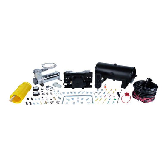
WirelessAIR™ Tank Systems combine a manifold and compressor into a tank system,
along with a wiring harness and accessories needed to connect to vehicle power and air
springs (purchased separately). The upgrade system allows you to upgrade your existing
system into a tank system with all the appropriate integration pieces.
NOTATION EXPLANATION
Hazard notations highlight information that must be observed to help minimize risk of
personal injury or possible improper installation, which may render the vehicle unsafe.
INDICATES IMMEDIATE HAZARDS WHICH WILL RESULT IN SEVERE PERSONAL INJURY
DANGER
OR DEATH.
INDICATES HAZARDS OR UNSAFE PRACTICES WHICH COULD RESULT IN SEVERE
WARNING
PERSONAL INJURY OR DEATH.
INDICATES HAZARDS OR UNSAFE PRACTICES WHICH COULD RESULT IN DAMAGE TO
CAUTION
THE MACHINE OR MINOR PERSONAL INJURY.
TOOLS LIST
Description ................................................. Qty
Power drill .............................................................1
1/4", 3/8" Drill bits ..........................................1 ea.
Grinder ..................................................................1
Standard wrench set ............................................1
3/8", 1/2", 5/16", 9/16" Sockets & ratchet .....1 ea.
MN-1183 • (012304) • ERN 9473
IMPORTANT: PLEASE READ BEFORE INSTALLING
IT IS IMPORTANT TO READ AND UNDERSTAND THE ENTIRE INSTALLATION GUIDE
BEFORE BEGINNING INSTALLATION OR PERFORMING ANY MAINTENANCE,
SERVICE OR REPAIR. THE INFORMATION HERE INCLUDES A HARDWARE LIST,
STEP-BY-STEP INSTALLATION INFORMATION AND SAFETY INFORMATION.
USING THE SYSTEM
Refer to the WirelessAIR™ User Guide included with this kit
to learn how to operate the system, connect the wireless
controller and connect your mobile device to the system.
Kit Number
EZ Mount & Upgrade Tank System
Installation Guide
WirelessAir User Guide
Description ................................................. Qty
3/32 Hex key ........................................................1
Wire stripping/crimping tool .................................1
Sharp razor knife ..................................................1
Lighter or torch .....................................................1
Teflon tape ............................................................1
74100EZ &
74100
User Guide
1
Advertisement
Table of Contents

Related Manuals for Air Lift WirelessAIR 74100EZ


Summary of Contents for Air Lift WirelessAIR 74100EZ
- Page 1 Kit Number 74100EZ & 74100 EZ Mount & Upgrade Tank System Installation Guide Introduction WirelessAIR™ Tank Systems combine a manifold and compressor into a tank system, along with a wiring harness and accessories needed to connect to vehicle power and air springs (purchased separately).
- Page 2 Protect your Air Lift Purchase by Completing your Warranty Registration Thank you for purchasing an Air Lift load support product! Take a photo of your sales receipt and then scan the QR code to complete your online warranty registration.
-
Page 3: Table Of Contents
TABLE OF CONTENTS Introduction Notation Explanation Tools List Hardware Lists Suggested Component Layout EZ Mount Bracket Preparation Remote Mount the Filter/Pressure Switch/Solenoid Assembly (Upgrade Systems Only) Prepare the Tank (Tank Kit) Compressor Installation Remote Air Filter Installation Tank Installation Mounting the Filter/Pressure Switch/Solenoid Bracket (Upgrade Systems Only) Install WirelessAIR Tank + EZ Mount Frame Rail Component Wiring Engine Compartment Component Wiring... -
Page 4: Hardware Lists
Hardware Lists WIRELESS AIR TANK UPGRADE (74100) Item Part # Description ....................Qty 11175 Air tank, 2 gallon ....................1 16544 Compressor, 444C chrome ..................1 26927 Harness, Wireless Air tank ..................1 22043 Air line, tire fill (coiled) ....................1 20230 Air line, 1/4" (30’) ....................1 Hardware Pack (33044): 10466 Zip tie, 8"... - Page 5 Tank + WIRELESS AIR EZ MOUNT TANK SYSTEM (74100EZ) Item Part # Description ....................Qty 11175 Air tank, 2 gallon ....................1 73006 Wireless Air Display ....................1 26566 EZ Mount assembly ....................1 16544 Compressor, 444C chrome ..................1 26927 Harness, Wireless Air tank ..................1 22043 Air line, tire fill (coiled) ....................1 20230...
-
Page 6: Suggested Component Layout
IMPORTANT - PLEASE READ If you purchased the upgrade kit, this installation guide will walk you through the steps to complete the finished installation. Before beginning, be aware that the compressor, wiring harness and electrical connections currently on your vehicle will NOT be used and will have to be removed before this process can be started. -
Page 7: Ez Mount Bracket Preparation
Tank + EZ Mount Bracket Preparation If you purchased the upgrade kit, you Vertical Orientation (How it ships) NOTE can skip to the Remote Mount Filter Air line Assembly section. Once the component layout has been deter- mined, choose how to mount your EZ Mount bracket, horizontally or vertically. -
Page 8: Remote Mount The Filter/Pressure Switch/Solenoid Assembly (Upgrade Systems Only)
Remote Mount the Filter/Pressure Switch/Solenoid Assembly (Upgrade Systems Only) If you purchased the upgrade system, a bracket (7A) comes included that allows you to easily NOTE remote mount this assembly (Fig. 5). You can pre-build this assembly ahead of putting it on your vehicle for greater ease of installation. -
Page 9: Prepare The Tank (Tank Kit)
Tank + Prepare the Tank (Tank Kit) 1. Know which direction you plan to mount the tank with respect to the other components before starting to install the necessary fittings for proper setup (Figs. 6 & 12). 2. Install the drain cock (II) into the tank port that is meant to point to the ground (Fig. 6). Apply tape or pipe dope and install 1 1/2-2 turns beyond finger-tight. -
Page 10: Compressor Installation
Compressor Installation 1. If you are not installing the leader line directly to the tank, attach the straight PTC fitting (KK) to the end of the leader line (Fig. 7). Apply tape or pipe dope and install 1 1/2-2 turns beyond finger-tight. 2. -
Page 11: Tank Installation
Tank + Tank Installation 1. Now that the component layout plan is completed and the tank is prepped, you are ready to install it to the vehicle. Please refer to the Installation Diagram (Fig. 12). 2. There are two mounting options: 1) hex cap screw (N), flat washer (M), lock washer (P) and lock nut (L);... - Page 12 10 2. EZ Mount can be mounted in any orientation except with the Air Lift logo upside down or with the Air Lift logo facing the ground (Fig. 11). There are mounting holes in the web of the EZ Mount bracket and in the top flange.
-
Page 13: Frame Rail Component Wiring
Tank + Frame Rail Component Wiring The integration steps may be different based on the way the system is mounted. Shown below are the connections that need to be made: a. Manifold Connector: Install the connector off the main harness (B) to the manifold. You should hear an audible click when attaching the connector to the manifold. - Page 14 MN-1183...
- Page 15 Tank + MN-1183...
-
Page 16: Remote Mount The Fill Port
1. Attach a supplied female push-on connector to the other end of the fuse holder using the correct size for the needed adapter (Fig. 13). Fuse Adapter Types: Adapter #1 Adapter #2 Adapter fig. 13 Fuse Uses 3/16" (smaller) female push-on connector 2. -
Page 17: Cutting Air Lines
The minimum bend radius for 1/4" air line is 1" (25mm). Air lines are to be installed straight into fittings. Inspect the air line for scratches that run lengthwise. Contact Air Lift customer service if the air line is damaged. Bad cut Good cut fig. - Page 19 fig. 19...
- Page 21 HAS BEEN PRINTED AT 100% SCALE. inch CAUTION DO NOT MOUNT EZ MOUNT WITH THE WIRING HARNESS CONNECTOR OR AIR LIFT LOGO POINTED DOWN (FIG. 11). DO NOT HANG EZ MOUNT FROM A HORIZONTAL SURFACE USING SELF- TAPPING SCREWS. PLACE THE COMPONENTS AND...
- Page 23 fig. 21...
- Page 25 fig. 22...
-
Page 26: Limited Warranty And Return Policy
• To submit a warranty claim, please visit https://www.airliftcompany.com/support/warranty/submit-claim/ Replacement Part Information If replacement parts are needed, contact the local dealer or call Air Lift customer service at (800) 248-0892. Most parts are immediately available and can be shipped the same day. Contact Air Lift Company customer... - Page 28 For the latest version of this manual, contact Air Lift Company at (800) 248-0892 or visit www.airliftcompany.com. Air Lift Company • 2727 Snow Road • Lansing, MI 48917 or P.O. Box 80167 • Lansing, MI 48908-0167 Toll Free (800) 248-0892 • Local (517) 322-2144 • Fax (517) 322-0240 • www.airliftcompany.com...
Need help?
Do you have a question about the WirelessAIR 74100EZ and is the answer not in the manual?
Questions and answers