
Related Manuals for ABB Terra HP Generation 4 CE Ionity


Summary of Contents for ABB Terra HP Generation 4 CE Ionity
- Page 1 Installation manual Terra HP Generation 4 CE Ionity © Copyright ABB. All rights reserved...
- Page 2 Copyright All rights to copyrights, registered trademarks, and trademarks reside with their respective owners. ® Copyright ABB E-mobility Inc.. All rights reserved. 6AGA000032-0115-EN | 004...
-
Page 3: Table Of Contents
Contents Contents About this document................8 Function of this document...................... 8 Target group..........................8 Revision history..........................8 Language.............................8 Illustrations..........................8 Units of measurement......................8 Typographical conventions..................... 8 How to use this document...................... 8 General symbols and signal words..................9 1.10 Special symbols for warnings and dangers............... 10 1.11 Related documents......................... - Page 4 Contents 3.5.5 Cable glands in the power cabinet..............24 3.5.6 Charge post, outside....................24 3.5.7 Charge post, inside....................25 3.5.8 Overview of the cable glands of the charge post..........26 Electric Vehicle Site Solution Control 202 (EVSS)..............26 Tilt Sensor Supply........................27 EV charge cable, CCS 2......................27 Parking sensor..........................27 3.10 Options............................
- Page 5 Contents 6.2.2 Install the cabinet on the foundation..............42 6.2.3 Install the cover plates of the metal foundation..........42 Mechanical installation of the charge post................43 6.3.1 Install the charge post - general procedure............43 6.3.2 Remove the cable gland plates................43 6.3.3 Install the charge post on the foundation............44 6.3.4...
- Page 6 Contents 11.3 Install insulating heatshrink tubing on a wire..............65 11.4 Connect a wire that has a cable lug..................66 11.5 Connect a wire that has a ferrule..................66 Technical data..................67 12.1 EVSE type..........................67 12.2 Parts included in the delivery....................67 12.3 Required tools for installation....................68 12.4...
- Page 7 Contents 12.18.2 DC power installation cables ................93 12.18.3 PE cable........................93 12.18.4 AC auxiliary power cables..................94 12.18.5 Interlock and DC guard cables................94 12.18.6 Ethernet cable between the power cabinet and the charge post....95 12.19 Electrical connection diagram....................96 12.20 Expected wye input.........................97 Appendix....................
-
Page 8: About This Document
About this document About this document Function of this document The document is only applicable for this EVSE: Terra HP Generation 4 Ionity, including the variants and options listed in section 12.1. The document gives the information that is necessary to install the EVSE. Target group The document is intended for qualified installation persons. -
Page 9: General Symbols And Signal Words
About this document General symbols and signal words Signal word Description Symbol Danger If you do not obey the instruction, this Refer to section can cause injury or death. 1.10. Warning If you do not obey the instruction, this Refer to section can cause injury. -
Page 10: Special Symbols For Warnings And Dangers
Qualified installation person EVSS Installation manual Qualified installation person User manual Owner Service manual Qualified service engineer Declaration of conformity (CE) All target groups 1.12 Manufacturer and contact data Manufacturer ABB E-mobility Inc. Heertjeslaan 6 2629 JG Delft 6AGA000032-0115-EN | 004... -
Page 11: Abbreviations
About this document The Netherlands Contact data ABB E-mobility Inc. in your country can give you support on the EVSE. You can find the contact data here: https://new.abb.com/ev-charging 1.13 Abbreviations Abbreviation Definition Alternating current BESS Battery energy storage system Controller area network... -
Page 12: Orientation Agreements
About this document Term Definition Grid provider Company that is responsible for the transport and dis- tribution of electricity Local rules All rules that apply to the EVSE during the entire lifecy- cle of the EVSE. The local rules also include the national laws and regulations Open charge point proto- Open standard for communication with charge sta-... -
Page 13: Safety
Safety Safety Liability The manufacturer is not liable to the purchaser of the EVSE or to third parties for damages, losses, costs or expenses incurred by the purchaser or third parties if any target group mentioned in the related documents does not obey the rules below: •... -
Page 14: Personal Protective Equipment
Safety Personal protective equipment Symbol Description Protective clothing Safety gloves Safety shoes Safety glasses Safety instructions during transport Preliminary requirements • Installation engineer • • Make sure that the hoisting equipment or forklift truck can lift the EVSE safely. Take into account the mass and the center of gravity of the EVSE. •... -
Page 15: Safety Instructions For Earthing
Safety • Make sure that the load capacity of the grid is in accordance with the EVSE. • Earth the EVSE correctly. Refer to section 2.7. • Make sure that the wiring inside the EVSE is protected from damage and cannot get trapped when you open or close the cabinet. -
Page 16: Discard The Evse Or Parts Of The Evse
Safety Symbol Description Appliance class 1 Sign that means that you must read the manual before you install the EVSE Waste from electrical and electronic equipment Note: It is possible that not all symbols are present on the EVSE. Discard the EVSE or parts of the EVSE Incorrect waste handling can have a negative effect on the environment and human health due to potential hazardous substances. - Page 17 Safety The manufacturer (ABB E-mobility Inc.) and its affiliates are not liable for damages and/or losses related to such security breaches, any unauthorized access, interference, intrusion, leakage and/or theft of data or information. 6AGA000032-0115-EN | 004...
-
Page 18: Description
The properties of the electrical grid, the ambient conditions and the EV must comply with the technical data of the EVSE. Refer to chapter 12. • Only use the EVSE with accessories that are approved by the manufacturer (ABB E-mobility Inc.) and that obey the local rules. •... -
Page 19: General Description Of The Evse
Description Note: For the German market the charge post is equipped with energy metering to comply with the 2014/32/EU MID directive. The energy meter is a field installable device. General description of the EVSE The EVSE is an arrangement of these parts: •... -
Page 20: Overview And Functions
Description Lines Description AC input power connections DC power connections Control lines (general) DC auxiliary power supply line Overview and functions 3.5.1 Power cabinet, outside Plinth cover Door Type plate Air outlet Silenced air intake Enclosure Part Function Plinth cover To cover the bottom part of the EVSE Air inlet and outlet To let the air in and out. -
Page 21: Power Cabinet, Inside
Description 3.5.2 Power cabinet, inside AC contactor Cable inlet Main switch DC plate PE busbar DC output terminal block AC plate Part Function AC contactor To connect the AC power Main switch To connect or disconnect the AC power PE busbar To connect PE cables AC plate To connect the AC and the precommissioning cables... -
Page 22: Ac Plate
Description 3.5.3 AC plate Terminal X1 Terminal X3 Terminal X2 Part Function Terminal X1 To connect the precommissioning cables Terminal X2 To connect the AC cables Terminal X3 To connect the AC cables 6AGA000032-0115-EN | 004... -
Page 23: Dc Plate
Description 3.5.4 DC plate Terminal X4 Ethernet connector Earthing terminal Part Function Terminal X4 To connect the interlock and DC guard cables Earthing terminal To connect the ground wire or shield mesh Ethernet connector To connect the Ethernet cable between power cabinet and charge post 6AGA000032-0115-EN | 004... -
Page 24: Cable Glands In The Power Cabinet
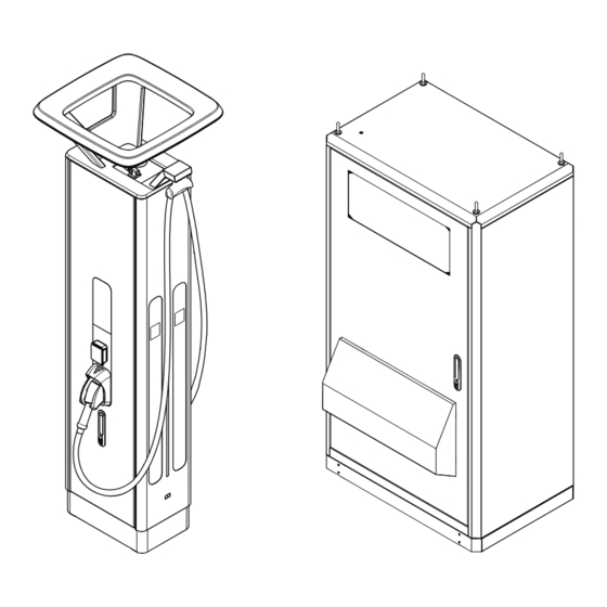
Description 3.5.5 Cable glands in the power cabinet AC and PE cable Charge post interconnection signals DC- and PE connections AC Charge post line feeding and AC precommissioning line input 3.5.6 Charge post, outside 6AGA000032-0115-EN | 004... -
Page 25: Charge Post, Inside
Description Door Air inlet and outlet Touchscreen Enclosure RFID reader and the payment Cable retraction system terminal (option) Antenna Stop button Hoisting points Connector holder LED strip EV charge cable Plinth cover Type plate Parking sensor 3.5.7 Charge post, inside Cooling unit Q1 RCD (residual current circuit DC power busbars... -
Page 26: Overview Of The Cable Glands Of The Charge Post
Description 3.5.8 Overview of the cable glands of the charge post PE wire Interlock and DC guard cable AC auxiliary power cable Ethernet cable PE wire DC+ in cable PE wire DC+ in cable Ethernet cable DC- in cable Not used DC- in cable Electric Vehicle Site Solution Control 202 (EVSS) The EVSS Control 202 basic functionality is the load management of an EV charging... -
Page 27: Ev Charge Cable, Ccs 2
OCPP. 3.10.2 Payment terminal The touchscreen guides the user how to use the payment terminal. Note: • To use and adjust the settings of the payment terminal, you require the ABB Payment Web tool. 6AGA000032-0115-EN | 004... -
Page 28: Fiscal Metering System
Description 3.10.3 Fiscal metering system The EVSE can optionally be equipped with an MID compliant DC energy meter. This upgrade can be installed in the factory or in the field. Time (hh:mm:ss) Delivered DC power (kWh) Date (YY-MM-DD) Note: The presence of the MID compliant DC meter is mandatory in some countries. -
Page 29: Pre-Installation
Pre-installation Pre-installation Pre-installation procedure (site planning) Preliminary requirements • All required permits to comply with the local rules, are granted. Procedure 1. Do a check on the configuration of the EVSE. Refer to the order. 2. Refer to the specifications to prepare and order these items: •... -
Page 30: Make Sure That The Floor Space For The Evse And The Airflow Around The Evse Is Correct
Pre-installation 7. Make sure that the site complies with the relevant usability standards, such as ADA and DIN 18040: a. Limit the curb heights. b. Take into account the limited reach of a wheelchair user. For usability standards specifications, refer to section 12.14.3. 8. -
Page 31: Prepare A Metal Foundation For The Power Cabinet
Pre-installation Procedure 1. Contact the manufacturer to order the foundation for your EVSE. Refer to section 1.12. 2. Dig the hole for the foundation. Caution: Make sure that the top surface of the foundation is above the ground level, to prevent intrusion of water. -
Page 32: Prepare A Prefab Concrete Foundation For The Charge Post
Pre-installation 4.4.4 Prepare a prefab concrete foundation for the charge post Preliminary requirements • Prefab concrete foundation. Refer to section 12.16.5. Procedure 1. Contact the manufacturer to order the foundation for your EVSE. Refer to section 1.12. 2. Dig the hole for the foundation. Caution: •... -
Page 33: Prepare A Metal Foundationfor The Charge Post
Pre-installation 4.4.5 Prepare a metal foundation for the charge post Preliminary requirements • Drill with screw tap • Metal frame. Refer to section 12.16.4. • Torque wrench If you have not included the foundation in the initial order, contact the manufacturer to order the foundation for your power cabinet. -
Page 34: Install The Grommet Plate For The Concrete Foundation Of The Power Cabinet
Pre-installation Procedure 1. Make the custom foundation. Caution: Make sure that the top surface of the foundation is above the ground level, to prevent intrusion of water. 2. Guide the cables into the holes (C1) to (C4) of the foundations. For the relation between the cables and the holes, refer to section 12.16.7. - Page 35 Pre-installation 6AGA000032-0115-EN | 004...
-
Page 36: Inspection And Transport
Inspection and transport Inspection and transport Transport the EVSE to the site A transport company delivers the EVSE close to the site. The movement of the EVSE to its final location is your responsibility. • If you need to store the EVSE before installation, obey the ambient conditions for storage. -
Page 37: Remove The Cabinet From The Pallet
Inspection and transport Remove the cabinet from the pallet Preliminary requirements • Open spanner Procedure 1. Remove the fasteners (A). 2. Discard the fasteners and the pallet. Refer to section 2.9. Transport the EVSE on the site 5.6.1 General transport procedure Preliminary requirements •... -
Page 38: Tilt The Charge Post To The Vertical Position
Inspection and transport Procedure 1. Move the power cabinet to the installation location: • Move the cabinet with a forklift truck. Refer to section 5.6.3. • Hoist the cabinet. Refer to section 5.6.4. 2. Move the charge post to the installation location: Situation Procedure Tilt the charge post to the vertical... -
Page 39: Move The Cabinet With A Forklift Truck
Inspection and transport 5.6.3 Move the cabinet with a forklift truck Preliminary requirements • The cabinet is unpacked. • Forklift truck. Refer to Refer to section 5.4. section 12.3. Warning: Risk of pinching or crushing, the cabinet is heavy • Make sure that the forklift truck can lift the cabinet safely. - Page 40 Inspection and transport Caution: • Do not drop the cabinet. • Make sure that there are no dynamic forces on the hoisting points. • Make sure that the weight is equally distributed between the hoisting points. Procedure 1. Install the swivel eye bolts or bolts with lifting loops (A).
-
Page 41: Installation
Installation Installation General installation procedure Preliminary requirements • The AC input cable is • There is no voltage on available. the AC input cable during the complete installation • The foundations for the procedure. cabinets are prepared. • All cables are in the cable entries or the grommet plate and the full cable slack is applied. -
Page 42: Install The Cabinet On The Foundation
Installation 6.2.2 Install the cabinet on the foundation Preliminary requirements • Hoisting equipment or • Four fasteners M16 and forklift truck washers • Torque wrench Procedure 1. Carefully lower the cabinet on the foundation with a hoisting equipment or a forklift truck. Refer to section 5.6.1. -
Page 43: Mechanical Installation Of The Charge Post
Installation Mechanical installation of the charge post 6.3.1 Install the charge post - general procedure Preliminary requirements • The charge post is above the foundation. Warning: Make sure that you secure the load when you do work below the charge post. Obey all related local regulations. Note: The manufacturer installed the cooling unit at the factory, including the cooling liquid. -
Page 44: Install The Charge Post On The Foundation
Installation 6.3.3 Install the charge post on the foundation Preliminary requirements • Hoisting equipment or • Six fasteners M12 and forklift truck washers • Torque wrench • Drop in anchors, for easy installation and quality Procedure 1. Carefully lower the charge post on the foundation with a hoisting equipment or a forklift truck. -
Page 45: Electrical Installation Of The Power Cabinet
Electrical installation of the power cabinet Electrical installation of the power cabinet General procedure Note: For a detailed overview of all electrical connections, refer to section 12.19. Preliminary requirements • The DC cables are • installed in one of the cable conduits. -
Page 46: Connect The Pe Cable
Electrical installation of the power cabinet Procedure 1. Attach the PE cable (A) to the PE busbar (B). with a loop.Use the fasteners (D). The loop is necessary to make sure that the PE cable is not the first wire that is disconnected when a collision moves the charge post. -
Page 47: Connect The Ac Power Cables In The Power Cabinet
Electrical installation of the power cabinet Connect the DC power cable in the power cabinet Preliminary requirements • Wire stripper pliers • • Wire cutter • Torque wrench • Cable lug • Fasteners M11 Procedure 1. Prepare the DC+ cables: a. -
Page 48: Connect The Ac Auxiliary Power Cable In The Power Cabinet
Electrical installation of the power cabinet Connect the AC auxiliary cable in the power cabinet Preliminary requirements • Torque screwdriver, cross • • Wire cutter • Wire stripper pliers • Crimp pliers • AC auxiliary power cable. Refer to section 12.18.4. •... -
Page 49: Connect The Interlock And Dc Guard Cables To The Power Cabinet
Electrical installation of the power cabinet Connect the interlock and DC guard cables to the power cabinet Preliminary requirements • Interlock and DC guard • cable. Refer to section 12.18.5. Note: The illustration shows the terminal block X9 on the power cabinet and the connections treated in this section. -
Page 50: Connect The Ethernet Cable Between The Power Cabinet And The Charge Post
Electrical installation of the power cabinet Connect the Ethernet cable to the power cabinet Preliminary requirements • Ethernet cable with an RJ45 plug. Refer to section 12.18.7 Procedure 1. Guide the cable to the Ethernet con- nector (A) 2. Connect the RJ45 plug to the Ethernet connector. -
Page 51: Electrical Installation Of The Charge Post
Electrical installation of the charge post Electrical installation of the charge post General procedure Note: For a detailed overview of all electrical connections, refer to section 12.19. Preliminary requirements • The DC power cables are • installed in one of the cable conduits. -
Page 52: Connect The Dc Power Input Cables
Electrical installation of the charge post b. Strip the insulation from the end of the wire. Make sure that the strip length is compatible with the cable lug. c. Attach the cable lug (C) to the end of the wire. 2. -
Page 53: Connect The Ac Auxiliary Power Cable
Electrical installation of the charge post Connect the AC auxiliary power cable Preliminary requirements • Wire cutter • • Wire stripper pliers • Torque screwdriver, cross • Crimp pliers • AC auxiliary power cable • Ferrules Note: The AC auxiliary power cable provides the control power to the charge post. -
Page 54: Connect The Interlock And Dc Guard Cable
Electrical installation of the charge post Procedure 1. Prepare ferrules for the wires that are -X20 mentioned below. Refer to section 11.2. 2. Connect these wires from the power cabinet: Wires from the power Connect to terminal Terminal name cabinet (A) Ground wire or shield X20-1 mesh... -
Page 55: Pre-Commissioning Mode
Electrical installation of the charge post Pre-commissioning mode If it is not possible to complete commissioning because it is not possible to supply the power cabinet from the main power line, it is necessary to set the charger in "precommissioning mode". In this way it is possible to avoid condensation phenomena inside the charger. -
Page 56: Prepare For Commissioning
Prepare for commissioning Prepare for commissioning Preliminary requirements • Installation engineer Danger: Hazardous voltage • Do not commission the EVSE. Only a service engineer of the manufacturer is qualified to commission the EVSE. Procedure 1. Tell the owner that the EVSE is ready for commissioning. 2. -
Page 57: Access To Parts
Access to parts Access to parts 10.1 Open the door of the power cabinet Preliminary requirements • Door key of the power cabinet Danger: Hazardous voltage • Make sure that only qualified personnel has access to the door key. Note: There is one unique door key for each power cabinet. Procedure 1. -
Page 58: Open The Dc Door
Access to parts Procedure 1. Remove these parts: • Fasteners (A) • Plinth covers (B) 10.3 Open the DC door Preliminary requirements • Door key of the DC door Danger: Hazardous voltage • Make sure that only qualified personnel has access to the door key. Procedure 1. -
Page 59: Close The Door Of The Power Cabinet
Access to parts Procedure 1. Set the main switch to off. 2. Remove the fasteners (A). 3. Remove the AC cover (B). 10.5 Close the door of the power cabinet Preliminary requirements • Door key to the power cabinet. Danger: Hazardous voltage •... -
Page 60: Open The Door Of The Charge Post
Access to parts 10.6 Open the door of the charge post Preliminary requirements • Door key of the charge post Danger: Hazardous voltage • Make sure that only qualified personnel has access to the door key. Note: • There is one unique door key for each charge post. •... -
Page 61: Remove The Protection Plate Of The Charge Post
Access to parts Procedure 1. Remove these parts: • Fasteners (A) • Plinth covers (B) 10.8 Remove the protection plate of the charge post Preliminary requirements • Screwdriver, cross Procedure 1. Remove these parts: • Fasteners (A) • Protection plate (B) 10.9 Install the AC cover Preliminary requirements... -
Page 62: Close The Dc Door
Access to parts Procedure 1. Install the AC cover (A). 2. Install the fasteners (B). 3. Set the main switch to on. 10.10 Close the DC door Preliminary requirements • Door key of the DC door Danger: Hazardous voltage • Make sure that only qualified personnel has access to the door key. - Page 63 Access to parts Danger: Hazardous voltage • Make sure that only qualified personnel has access to the door key. Note: There is one unique door key for each charge post. Procedure 1. Close the door (A). 2. Turn the handle (B) counterclockwise. 3.
-
Page 64: Generic Procedures
Generic procedures Generic procedures 11.1 Install a cable lug on a wire Preliminary requirements • Wire cutter • • Wire stripper pliers • Crimp plier • Cable lug Procedure 1. Make sure that the diameter of the cable lug is correct. The cable lug must be compatible with the wire. -
Page 65: Install Insulating Heatshrink Tubing On A Wire
Generic procedures Procedure 1. Make sure that the diameter of the ferrule is correct. The ferrule must be compatible with the wire. Obey the technical specifications set by the manufacturer. Refer to section 12.18. 2. Strip the insulation from the wire. The stripped length must be the same as the length of the cavity of the ferrule. -
Page 66: Connect A Wire That Has A Cable Lug
Generic procedures 11.4 Connect a wire that has a cable lug Preliminary requirements • Torque screwdriver, cross • Procedure 1. Loosen the bolt of the connection pin (A) on the busbar (B). 2. Install the eye of the cable lug (C) on the connection pin. -
Page 67: Technical Data
Technical data Technical data 12.1 EVSE type The EVSE type is a code, mentioned on the type plate. Refer to section 3.2. The code is made out of 3 parts: T U V Code part Description Value Meaning of the value Model Terra high power Part... -
Page 68: Required Tools For Installation
Technical data 12.3 Required tools for installation Parameter Specification Hoisting equipment or forklift truck Capable to lift the EVSE safely. Take into account the dimensions, the mass, and the center of gravity. Swivel eye bolts or bolts with lifting Thread M10 for the charge post loops (to use with hoisting equipment) Thread M16 for the power cabinet As a standard, eye bolts are installed on... -
Page 69: General Specifications
Technical data 12.5 General specifications Parameter Specification Compliance and safety Ingress protection rating IP54 EMC rating for the charge post The charge post complies with these standards: • EN 61000-6-3 : 2007 + A1: 2001 Emis- sion standard for residential, com- mercial and light-industrial environ- ments (Class B) •... -
Page 70: Electrical Installation Specifications
Technical data 12.6 Electrical installation specifications 12.6.1 General requirements Parameter Specification Circuit breaker Use a circuit breaker with the option for an under voltage release device. Surge protection device Type 2 Residual-current device In the range of 30 mA up to 300 mA Power consumption of the power cabi- In standby status: ≤... -
Page 71: Requirements For Charge Post Auxiliary
Technical data Parameter Specification Input voltage range 230 V AC +/- 10 % (50 Hz or 60 Hz) Nomi- nal input Nominal input current 550 A at 400 V AC Maximum input current 15 A at 230 V AC Cores According to IEC 60446 Cross section range 3 x 4 mm... -
Page 72: Current Peaks During The Start Of A Charge Session (Dc Output)
Technical data 12.8 Current peaks during the start of a charge session (DC output) Parameter Specification Duration of the current peaks 25 µs Maximum current peak 60 A 12.9 Logic interfaces specifications Parameter Specification RFID standard ISO/IEC 14443A/B, ISO/IEC 15393 ™... -
Page 73: Center Of Gravity, Charge Post
Technical data Center of gravity Parameter Specification [mm] [in] 23.1 3.93 1068 42.1 12.10.3 Center of gravity, charge post Center of gravity Parameter Specification [mm] [in] 13.9 1096 43.2 12.11 Ambient conditions Parameter Specification Operation temperature -35 °C to +55 °C (-31 °F to +131 °F) Derating applies Storage +5 °C to +40 °C (+41 °F to 104 °F) -
Page 74: Noise Level
Technical data Parameter Specification IK10 (screen: IK08) Altitude Maximum 2000 m (6562 ft) above the sea level 12.12 Noise level Noise level Specification [dB(A)] Charge post, 500 A continuous up to ≤ 60 at 1 m (39.4 in) 35 °C Maximum noise level of the charge post 68 at 1 m (39.4 in) Power cabinet... -
Page 75: Dimensions
Technical data 12.14 Dimensions 12.14.1 Power cabinet Parameter Specification [mm] [in] Width (X-dimension) 1170 46.1 Depth (Y-dimension) 30.3 Height (Z-dimension) (including eye 2243 88.3 bolts) Required cable slack for the AC input ca- from 200 to 250 from 7.9 to 9.9 ble (measured from the top of the foun- dation) Required cable slack for the PE cable... -
Page 76: Height Of User Operable Elements
Technical data Parameter Specification [mm] [in] Required cable slack for the interlock 1200 47.2 and DC guard cable (measured from the top of the foundation) Required cable slack for the ETH cable 1200 47.2 (measured from the top of the founda- tion) Parameter Specification... -
Page 77: Space Requirements
Technical data Parameter Specification [mm] [in] Top of the authentication clus- 37.6 Bottom of the touch screen dis- 1026 play Advised maximum height for 1118 user operable elements if the EVSE is placed on a curb. This requires HMI customization. Top of the touch screen display 1223 48.1... -
Page 78: Charge Post
Technical data Parameter Specification for a single power cabinet [mm] [in] 1170 47.2 25.6 30.3 1050 41.3 25.6 Parameter Specifications for power cabinets side by side [mm] [in] 100 per power cabinet. 3.9 per power cabinet. Parameter Specifications for power cabinets back to back [mm] [in] 100 per power cabinet. -
Page 79: Charge Post: Exceptions For Bollards And Other Minor Fixed Obstacles
Technical data Charge post Space required for cable Total required width for the charge replacement post Total required depth for the charge Space required for the air inlet and post to open the side panel Maximum sideway reach of the Space required at the sides to open wheelchair user the door... -
Page 80: Distance Requirements Between Power Cabinet And Charge Post
Technical data Charge post Required depth to open the side Total width to open the side panels panel Required width to open the side Required depth to open the side panel panel Space required at the sides to open Total required width to open side the door panels Total required width to open the... -
Page 81: Foundation Specifications
Technical data 12.16 Foundation specifications 12.16.1 Power cabinet (prefab concrete) General specifications Parameter Specification Type Base monoblock of support for cabinet, with plasticizer and waterproofing addi- tive Concrete class C32 / 40 Exposure class CX4 and XD25 according to UNI 11104:2018 Dimensions, side view Parameter... - Page 82 Technical data Dimensions, front view Parameter Specification [mm] [in] 1200 47.2 21.8 13.9 23.6 6AGA000032-0115-EN | 004...
- Page 83 Technical data Dimensions, top view Y2 Y3 Parameter Specification [mm] [in] 1200 47.2 17.4 1050 41.3 31.5 25.6 24.2 Parameter Specification A (4x) B (6x) 6AGA000032-0115-EN | 004...
-
Page 84: Power Cabinet (Metal Frame)
Technical data 12.16.2 Power cabinet (metal frame) Gasket for the AC and signal gland Metal frame plate Width of the foundation Gland plates Depth of the foundation Gasket for the DC gland plate Height of the foundation Cover plate left and right Height of the gland plate Cover plate front and rear Parameter... -
Page 85: Gland Plates For The Metal Foundation Of The Power Cabinet
Technical data 12.16.3 Gland plates for the metal foundation of the power cabinet Parameter Specification [mm] [in] 13.8 18.1 6AGA000032-0115-EN | 004... -
Page 86: Charge Post (Metal Frame)
Technical data 12.16.4 Charge post (metal frame) Foundation Footprint of the foundation Front cover Width of the foundation Rear gland plate Depth of the foundation Left gland plate Height of the foundation Right gland plate Distance between the holes Cable trays Distance between the hole and the Tie plate edge of the footprint... -
Page 87: Charge Post (Prefab Concrete)
Technical data 12.16.5 Charge post (prefab concrete) Foundation mass and loads Parameter Specification Mass 1030 kg (2271 lb) 15.06 kN (3386 klbf) 5.25 kN (1180 klbf) 8.36 kNm (74.1 klb-in) Dimensions, side views Parameter Specification [mm] [in] 6.89 25.2 8.66 157.5 6.20 19.7... - Page 88 Technical data Parameter Specification 3° α1 Dimensions, top view D1 D2 Parameter Specification [mm] [in] 5.71 4.72 10.4 10.4 4.92 5.91 5.91 1400 55.1 17.3 D1, diameter 4.92 D2, diameter 4.92 D3, diameter 2.36 Parameter Specification 3° α1 Tube diameter for D1 125/119 mm (4.92/44.1 in) Tube diameter for D2 125/119 mm (4.92/44.1 in)
-
Page 89: Gland Plates For The Metal Foundation Of The Charge Post
Technical data Parameter Specification Tube diameter for D3 60/56 mm (2.36/2.20 in) A (2x) DEMU anchor type 1988 type M16 depth 20 (8.66) B (6x) DEMU T-FIXX A4 anchor type M12 depth 115 (4.53) 12.16.6 Gland plates for the metal foundation of the charge post Drilling area for the side gland Drilling area for the rear gland plate plate... -
Page 90: Charge Post (Custom)
Technical data 12.16.7 Charge post (custom) Note: The arrow shows the front side of the charge post. Parameter Specification A (6x) For M12 fasteners diameter 14 (0.6) Parameter Specification [mm] [in] 22.8 20.7 14.6 6AGA000032-0115-EN | 004... -
Page 91: Overview Of The Cable Conduits
Technical data Parameter Specification [mm] [in] Cable conduit hole Maximum diameter [mm] [in] Function for cable conduit holes, 350 kW static system Cable conduit Cable conduit for these cables hole Primary power cabinet Secondary power cabinet AC power AC power ETH, interlock and DC guard: to ETH, interlock and DC guard: to the secondary power cabinet... -
Page 92: Cable Specifications
Technical data Foundation of the power cabinet Foundation of the charge post Note: The arrows show the front side of the charge post and the power cabinet. Cable conduit Cables DC power AC auxiliary power Interlock DC guard AC power 12.18 Cable specifications 12.18.1... -
Page 93: Dc Power Installation Cables
Technical data Parameter Specification Insulation PVC that is serviceable for outdoor use, UV-protected, and oil resistant Minimum nominal voltage Uo/U 450/750 VAC Minimum test voltage 4 kV Ambient temperature range -40 °C to +80 °C (-40 °F to +176 °F) Diameter of the PE conductor The same as the diameter of the phase conductors... -
Page 94: Ac Auxiliary Power Cables
Technical data Parameter Specification Conductor Fine strand copper wire according to VDE 0295 Cl. 5/ IEC 60228 Cl. 5 Insulation Special PVC that is serviceable for out- door use, UV-protected, and oil resistant Minimum nominal voltage Uo/U 600/1000 Vac Minimum test voltage 4 kV Ambient temperature range -40°C to 80°C (-40 °F to +176 °F) -
Page 95: Ethernet Cable Between The Power Cabinet And The Charge Post
Technical data 12.18.6 Ethernet cable between the power cabinet and the charge post Parameter Specification Type Shielded (tinned copper braid) Number of (twisted) pairs 4 x 2 Core identification Acc. to DIN 47100 Cross section 0.5 - 0.75 mm² Diameter 5 - 10mm Conductor Fine strand copper wire... -
Page 96: Electrical Connection Diagram
Technical data 12.19 Electrical connection diagram 6AGA000032-0115-EN | 004... -
Page 97: Expected Wye Input
Technical data 12.20 Expected wye input Canada 600 V 480 V 347 V 277 V 6AGA000032-0115-EN | 004...