Table of Contents
Advertisement
Quick Links
®
™
EMC
VNX
Family
™
VNX5700
Hardware Information Guide
REV A03
October, 2011
This guide describes one of five models available in the VNX Series, the EMC
VNX5700™. This document provides an overview of the architecture, components, and
features of the VNX5700. The specific aspects of the Block and File (Unified) VNX5700
platform and its major components include the front and rear connectors and LED
indicators on the storage processor enclosure (SPE), the 1U or 2U standby power supply
(SPS), the Control Station, the Data Mover enclosure, and the 2U, 25 (2.5-inch), the 3U, 15
(3.5-inch), or the 4U, 60 (2.5-inch or 3.5-inch) disk drive disk-array enclosure (DAE).
This guide is available online at https://mydocs.emc.com/VNX/. Go to the About VNX
section, and then select Learn about VNX. Next, follow the steps in the wizard.
Topics include:
Product software and hardware release revisions ...................................................... 4
◆
Revision history ........................................................................................................ 4
◆
Where to get help...................................................................................................... 4
◆
How this document is organized ............................................................................... 5
◆
Related documentation............................................................................................. 5
◆
Overview................................................................................................................... 6
◆
VNX5700 Block and File product description ............................................................. 8
◆
System component description ............................................................................... 17
◆
I/O modules............................................................................................................ 45
◆
Disk-array enclosure................................................................................................ 63
◆
Cabling ................................................................................................................... 95
◆
VNX5700 DAE cabling ............................................................................................. 96
◆
®
Advertisement
Table of Contents

Related Manuals for EMC VNX5700


Summary of Contents for EMC VNX5700
-
Page 1: Table Of Contents
This guide describes one of five models available in the VNX Series, the EMC VNX5700™. This document provides an overview of the architecture, components, and features of the VNX5700. The specific aspects of the Block and File (Unified) VNX5700 platform and its major components include the front and rear connectors and LED indicators on the storage processor enclosure (SPE), the 1U or 2U standby power supply (SPS), the Control Station, the Data Mover enclosure, and the 2U, 25 (2.5-inch), the 3U, 15... -
Page 2: Product Software And Hardware Release Revisions
Product software and hardware release revisions Product software and hardware release revisions As part of an effort to improve its product lines, EMC periodically releases revisions of its software and hardware. Therefore, some functions described in this document might not be supported by all versions of the software or hardware currently in use. -
Page 3: How This Document Is Organized
Description “Overview” on page 6 Describes the software and hardware features of a typical VNX5700 along with a front view example of the VNX5700. “VNX5700 Block and File Describes and shows the front and rear views of a typical product description” on page 8 VNX5700. -
Page 4: Overview
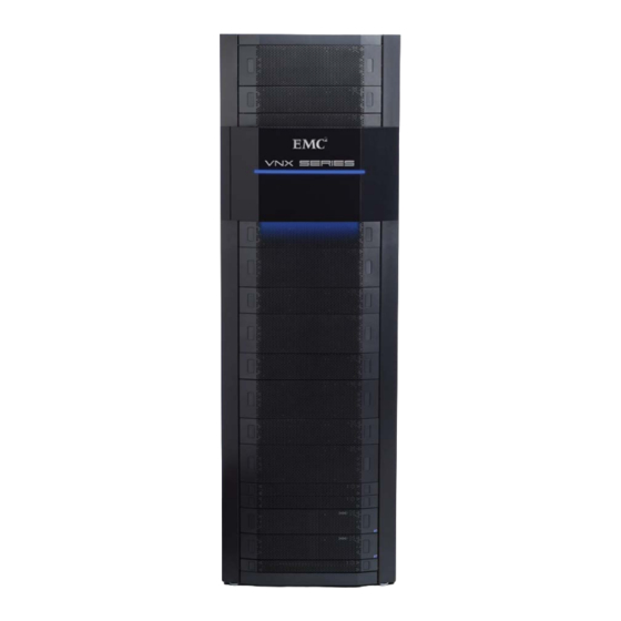
FC, iSCSI, and FCoE I/O connectivity to provide Block services to host simultaneously so as to provide file services to clients. The VNX5700 platform supports three types of DAEs; a 15 drive 3.5-inch disk 3U enclosure, a 25 drive 2.5-inch disk 2U enclosure, and a 60 drive 2.5- or 3.5-inch disk 4U enclosure. - Page 5 Overview ™ Updated unified management with Unisphere now delivering a more cohesive ◆ unified user experience VNX-000591 Figure 1 Example of a VNX5700 platform with front bezel VNX5700 Hardware Information Guide...
-
Page 6: Vnx5700 Block And File Product Description
Figure 2 Example of a Block and File VNX5700 platform (front view) 1. This configuration is true for a Block and File (Unified) VNX5700 platform. In the Block version, up to eight 4U DAEs and one 3U DAE (a maximum of 495 disk drives) is possible. - Page 7 Rear view Figure 3 shows an example of the rear view of the Block and File (Unified) VNX5700 platform configuration having a dual 1U SPS, an SPE with two storage processors (SP A and B, each SP includes a management module and two I/O modules), two Data Mover enclosures (with two Data Movers per enclosure), and two Control Stations.
- Page 8 VNX-000628 Figure 4 Example of a Block and File (Unified) VNX5700 platform using a 2U SPS (front view) 2. The term Data Mover is used throughout this guide. The term Data Mover is also referred to as a blade. These terms are interchangeable and basically mean the same.
- Page 9 Control Station 1 (optional) MGMT Control Station 0 Data Mover enclosure 1 Data Mover enclosure 0 Storage processor enclosure VNX-000630 Figure 5 Example of a Block and File (Unified) VNX5700 platform using a 2U SPS (rear view) VNX5700 Hardware Information Guide...
- Page 10 3 when the storage processor is assembled at the factory. However, if your Block and File (Unified) VNX5700 platform did not come from the factory this way, you can install the FC I/O module in slots 1, 2, or 3.
- Page 11 These cables will be supplied in lieu of the SFP+ when so ordered. 5. A VNX5700 Block and File (Unified) platform can only have 2, 3, or 4 Data Movers. VNX5700 Hardware Information Guide...
- Page 12 The CPU modules and the power supply/cooling (fan) modules plug directly into the midplane connections. 6. A fully loaded Block and File (Unified) VNX5700 platform includes two Control Stations, one SPE, one dual 2U SPS, and two Data Mover enclosures (with four Data Movers).
- Page 13 10 K 1. Does not include DAEs. 2. MPFS = Multi-Path File System 3. pNFS = parallel-NFS Configured for AC-input power, the Block and File VNX5700 platform includes the following hardware features: One dual 2U standby power supply (SPS) ◆...
- Page 14 Any required cables including LAN cables, modem cables, and serial DB-9 cable. ◆ Mounting rails with hardware ◆ Front bezel with VNX5700 badge ◆ 9. A VNX5700 Block and File (Unified) platform can only have 2, 3, or 4 Data Movers. VNX5700 Hardware Information Guide...
-
Page 15: System Component Description
Storage processor enclosure fault LED power LED VNX-000586 Figure 6 Storage processor enclosure LEDs 10. The dual 2U SPS is used in a VNX5700 platform environment when using the 4U, 60 disk drive DAE as a Vault drive. VNX5700 Hardware Information Guide... - Page 16 LED CNS-001669 Figure 7 CPU LEDs Table 4 CPU LEDs Color State Description Power Green Storage processor is powered up and all components in the Data Mover are operating properly. — Storage processor is powered down. VNX5700 Hardware Information Guide...
- Page 17 (fan) power/fault LED CNS-001673 Figure 8 Power supply/cooling (fan) module LED Table 5 Power supply/cooling (fan) module LED Color State Description Power/Fault Green Normal (no faults detected) Amber Blinking Power supplied but external fault detected Amber No power VNX5700 Hardware Information Guide...
- Page 18 System component description DME front view The front of the Block and File (Unified) VNX5700 platform Data Mover enclosure contains two enclosure status (power and fault) LEDs, as shown in Figure Table 6 describes the Data Mover enclosure power and fault LEDs.
- Page 19 Data Mover is unsafe to remove. remove — Data Mover is safe to remove. Note: The fault LED changes color from amber to blue when the operating system is loading, see step 4 in the description. VNX5700 Hardware Information Guide...
- Page 20 (fan) power/fault LED CNS-001673 Figure 11 Power supply/cooling (fan) module LED Table 8 Power supply/cooling (fan) module LED Color State Description Power/Fault Green Normal (no faults detected) Amber Blinking Power supplied but external fault detected Amber No power VNX5700 Hardware Information Guide...
- Page 21 System component description Control Station front view On the front, viewing from left to right, the Block and File (Unified) VNX5700 platform Control Station includes the following hardware components: DVD-ROM drive ◆ USB 2.0 connector (not used) ◆ Control switch and status LEDs ◆...
- Page 22 System component description Control Station switch and LEDs Figure 13 shows the location of the Block and File (Unified) VNX5700 platform Control Station switch and LEDs on the front panel. Table 9 describes the switch located on the front panel.
- Page 23 1. The system status LED flashes green while booting up. VNX5700 rear view On the rear, viewing from top to bottom, a Block and File (Unified) VNX5700 platform includes the following hardware components: One to two Control Stations ◆...
- Page 24 The Block and File (Unified) VNX5700 platform includes a dual 1U, 1.2-kilowatt standby power supplies (SPSs) to maintain power to the Block and File (Unified) VNX5700 platform SP during power loss. Within the SPS, a built-in DC battery pack is charged by way of an AC-DC converter.
- Page 25 Power out socket to the SP A power supply SPS B to SP B management (RJ-12) on the SPE connector Figure 14 Example of 1U SPS B and A viewing from left to right (rear view) VNX5700 Hardware Information Guide...
- Page 26 Both symbols mean that you cannot connect telephone type circuits to this connector (see the following WARNING). This port connects the 1U SPS (A and B) ports to the SP (A and B) ports, respectively. VNX5700 Hardware Information Guide...
- Page 27 RJ-12 connector (SPS side) on one end and a micro DB-9 connector (SP side) on the other end. Figure 17 shows an example of an SPS A to SP A cable. VNX-000283 Figure 17 Example of SP A (micro DB-9) SPS (RJ-12) cable VNX5700 Hardware Information Guide...
- Page 28 System component description 2U SPS rear view When using the Block and File (Unified) VNX5700 platform with the 4U, 60 disk drive DAE as the Vault drive in 40U Dense rack, the dual 2U, 2.2-kilowatt standby power supply (SPS) is used to maintain power to the Block and File (Unified) VNX5700 platform SP during power loss.
- Page 29 R-J12 jack. But an RJ-12 plug will fit into an RJ-45 jack. Use caution when connecting cables. To avoid electric shock, do not attempt to connect TNV circuits to SELV circuits. VNX5700 Hardware Information Guide...
- Page 30 RJ-12 connector (SPS side) on one end and a micro DB-9 connector (SP side) on the other end. Figure 21 shows an example of an SPS A to SP A cable. VNX-000283 Figure 21 Example of SP A (micro DB-9) SPS (RJ-12) cable VNX5700 Hardware Information Guide...
- Page 31 Four-port 8-Gb/s (4-Gb/s) FC I/O module SP management module Filler panel module 1. The management module in the Block and File VNX5700 platform SP comprises two types; one with a USB port and one without a USB port. Figure 23 on page 34 shows an example of the SP management module without the USB port.
- Page 32 Since the Control Station and the management module have the same type of management (RJ-45) ports, “Control Station Ethernet (RJ-45) ports” on page 42 provides detailed information about the SP management module ports, connector, and adapter. VNX5700 Hardware Information Guide...
- Page 33 Note: LED is always illuminated at powerup, until it is initialized. — SP Management module is powered down. Link (each Green Network connection port has — No network connection one) Activity Amber Blinking Transmit/receive activity (each port — No network activity has one) VNX5700 Hardware Information Guide...
- Page 34 System component description SP Management module serial console (DB-9) socket connector The back of the Block and File (Unified) VNX5700 platform SP management module includes two standard serial console Electronics Industries Association (EIA) RS-232 interface (DB-9) socket connectors (one labeled with a symbol depicting a wrench on the right and the other with a symbol depicting a battery on the left).
- Page 35 System component description DME rear view The rear of the Block and File (Unified) VNX5700 platform DME does not contain any LEDs (Figure 27). Only the management module and the I/O modules have LEDs. Note: Figure 27 is a graphical representation of the Block and File (Unified) VNX5700 platform DME rear view with two Data Movers (each Data Mover shows one management module, one four-port 8-Gb/s FC I/O module, and four filler panel modules).
- Page 36 Figure 28 Data Mover management module Data Mover management module Ethernet (RJ-45) ports The Block and File (Unified) VNX5700 platform Data Mover management module comes with three integrated dual-port Ethernet ports (labeled 0, 1, and 2) on the rear of the management module.
- Page 37 Blinking Transmit/receive activity (each port — No network activity has one) numeric — Displays the enclosure ID assigned to the Data Mover (7-segment) enclosure. display for Note: Each enclosure is assigned a number at installation. enclosure VNX5700 Hardware Information Guide...
- Page 38 Clear to send Request to send Ring indicator (not used) Control Station rear view On the rear, viewing from left to right, the Block and File (Unified) VNX5700 platform Control Station includes the following hardware components: AC power in connector ◆...
- Page 39 Control Station. Figure 31 VNX5700 platform Control Station (rear view) Control Station Input/output ports and connectors The Block and File (Unified) VNX5700 platform Control Station supports the following I/O ports on the rear of the Control Station: Four Ethernet (RJ-45) ports ◆...
- Page 40 System component description Control Station Ethernet (RJ-45) ports The Block and File (Unified) VNX5700 platform Control Station comes with two integrated dual-port Ethernet ports (labeled A and CS) and two Peripheral Component Interconnect Express (PCI-E) low profile card dual-port Ethernet ports (labeled B and MGMT) in an expansion slot on the rear of the Control Station.
- Page 41 Ethernet cable extensions for the Control Station B and MGMT ports Each Block and File (Unified) VNX5700 platform Control Station comes with two modular Ethernet cable extensions (or patch cords) for the RJ-45 ports (labeled on the CS as B and MGMT, respectively).
- Page 42 System component description Note: If you received the Block and File (Unified) VNX5700 platform already installed in a cabinet rack with all of the Block and File (Unified) VNX5700 platform components, all the cabling has already been installed. VNX-000564 Figure 34 Example of an Ethernet extension (modular plug to modular jack) cable...
-
Page 43: I/O Modules
I/O modules Control Station modem (DB-9) plug connector The back of the Block and File (Unified) VNX5700 platform Control Station includes a standard modem serial interface (DB-9) plug connector (labeled with a telephone handset icon on the left). Notice the orientation of the pins (Figure 36). - Page 44 I/O modules SP I/O module types The following I/O module types are supported by the Block and File (Unified) VNX5700 platform SP: “Four-port 8-Gb/s FC I/O module” on this page ◆ “Four-port 1-Gb/s copper iSCSI I/O module” on page 48 ◆...
- Page 45 Small form-factor pluggable (SFP+ ) transceiver module Blue faulted, unsupported, or optical cable fault. — No network connection 1. Refer to the VNX5700 Parts Location Guide for the part number label location for the SFP+ part number. VNX5700 Hardware Information Guide...
- Page 46 Push button latch handle RJ-45 link LED Power/fault LED RJ-45 activity LED RJ-45 (copper) port (four) Figure 39 Four-port 1-Gb/s copper iSCSI I/O module 14. iSCSI is a protocol for sending SCSI packets over TCP/IP networks. VNX5700 Hardware Information Guide...
- Page 47 I/O module is powered up. Amber I/O module has faulted. — I/O module is powered down. Link (each Green Network connection port has — No network connection one) Activity Amber Blinking Transmit/receive activity (each port — No activity has one) VNX5700 Hardware Information Guide...
- Page 48 These cables will be supplied in lieu of the SFP+ when so ordered. 16. iSCSI is a protocol for sending SCSI packets over TCP/IP networks. VNX5700 Hardware Information Guide...
- Page 49 SFF-8088 specification mini-SAS 26-circuit cable (plug) with a pull tab. The four-port 6-Gb/s SAS I/O module increases the back end capability of the VNX5700 platform. Basically, it adds an additional four back end buses to each SP in the SPE.
- Page 50 Four-port 6-Gb/s SAS I/O module LEDs The four-port 6-Gb/s SAS I/O module has two types of status LEDs. Figure 44 shows the LEDs and Table 27 describes them. Power/fault LED Link/activity LED VNX-000581 Figure 44 Four-port 6-Gb/s SAS I/O module LEDs VNX5700 Hardware Information Guide...
- Page 51 I/O module can interface at speeds up to 10 Gb/s for Fibre Channel over Ethernet networks. The two-port 10-Gb/s FCoE I/O module uses the SFP+ transceiver module. For VNX5700 Parts Location Guide part number label location, see the...
- Page 52 State Description Power/Fault Green I/O module is powered up. Amber I/O module has faulted. — I/O module is powered down. Link Green Network connection — No network connection Activity Amber Blinking Transmit/receive activity — No activity VNX5700 Hardware Information Guide...
- Page 53 I/O modules Data Mover I/O module types The following I/O module types are supported by the Block and File (Unified) VNX5700 platform Data Mover: “Four-port 8-Gb/s FC I/O module” on this page ◆ “Four-port 1-Gb/s copper I/O module” on page 57 ◆...
- Page 54 — No network connection 18. Be careful when replacing or swapping out SFP+ modules, the Data Mover will lose access to the SP or tape drive to which it is connected. VNX5700 Hardware Information Guide...
- Page 55 I/O modules VNX5700 Parts Location Guide 1. Refer to the for the correct SFP+ part number. Four-port 1-Gb/s copper I/O module The four-port 1-Gb/s copper I/O module comes with four copper ports, one power/fault LED, and a link and activity LED for each copper port (Figure 49).
- Page 56 I/O module is powered up. Amber I/O module has faulted. — I/O module is powered down. Link (each Green Network connection port has one) — No network connection Activity (each Amber Blinking Transmit/receive activity port has one) — No activity VNX5700 Hardware Information Guide...
- Page 57 SFP+ activity LED (left) Power/fault LED RJ-45 (copper) port (two) SFP+ (optical) port (two) RJ-45 link LED (right) SFP+ link LED (right) RJ-45 activity LED (left) Figure 51 Two-port 1-Gb/s copper plus two-port 1-Gb/s optical I/O module VNX5700 Hardware Information Guide...
- Page 58 I/O module is powered up. Amber I/O module has faulted. — I/O module is powered down. Link (each Green Network connection port has one) — No network connection Activity (each Amber Blinking Transmit/receive activity port has one) — No activity VNX5700 Hardware Information Guide...
- Page 59 19. The two-port 10-Gb/s I/O module can also use active twinaxial (Twinax) cables. Twinax is a type of cable similar to coax, but with two inner conductors instead of one. These cables will be supplied in lieu of the SFP+ transceiver module when so ordered. VNX5700 Hardware Information Guide...
- Page 60 State Description Power/Fault Green I/O module is powered up. Amber I/O module has faulted. — I/O module is powered down. Link Green Network connection — No network connection Activity Amber Blinking Transmit/receive activity — No activity VNX5700 Hardware Information Guide...
-
Page 61: Disk-Array Enclosure
DAE is used as the vault drive, the total disk drive count is 450 disk drives. 22. This configuration is true for a Block and File VNX5700 platform. In the Block version, up to eight 4U DAEs and one 3U DAE (a maximum of 495 disk drives) is possible. - Page 62 Each expander manages the drives it is connected to. The only shared resources are the LCC LED and the expander I C (inter-integrated circuit) bus. 25. The EA is sometimes referred to as an enclosure ID. VNX5700 Hardware Information Guide...
- Page 63 3U, 15 (3.5-inch) DAE front view On the front, viewing from left to right, the Block and File (Unified) VNX5700 platform 3U, 15 (3.5-inch) disk drive DAE carrier includes the following hardware components: 3.5-inch 6-Gb/s SAS, 6-Gb/s NL-SAS, or Flash disk drives (hot-swappable) ◆...
- Page 64 DAE power on LED (blue) Figure 55 3U, 15 (3.5-inch) disk drive (front view) Table 33 describes the Block and File (Unified) VNX5700 platform DAE and the 3.5-inch disk drive status LEDs Table 33 3U, 15 (3.5-inch) DAE and disk drive LEDs...
- Page 65 Each LCC independently monitors the environmental status of the entire enclosure, using a microcomputer-controlled monitor program. The monitor communicates the status to the storage processor, which polls disk enclosure status. LCC firmware also controls the SAS PHYs and the disk-module status LEDs. VNX5700 Hardware Information Guide...
- Page 66 DAE placement within a system. For example, the front DAE in some systems is in slot A; the rear enclosure LCC is inverted, and in slot B. 26. The enclosure ID is sometimes referred to as the enclosure address (EA). VNX5700 Hardware Information Guide...
- Page 67 The drives and LCCs have individual soft-start switches that protect the disk drives and LCCs if they are installed while the disk enclosure is powered up. The enclosure cooling system includes two dual-blower modules. VNX5700 Hardware Information Guide...
- Page 68 3U DAE LCC 6-Gb/s SAS port pin signals used on the connector. Table 35 6-Gb/s SAS port connector pinout Signal Signal Rx 0+ Tx 0+ Rx 0- Tx 0- Rx 1+ Tx 1+ Rx 1- Tx 1- Rx 2+ Tx 2+ Rx 2- Tx 2- VNX5700 Hardware Information Guide...
- Page 69 Description Link/activity Blue All lanes are running at 6 GB/s Green One or more lanes is not running at full speed or disconnected Alternating Blinking Port is being marked by the host Blue/Green — Not connected VNX5700 Hardware Information Guide...
- Page 70 (Figure 61). Bus (loop) status LEDs Bus (loop) ID LCC enclosure ID LCC B VNX-000107 Figure 61 Example of LCC B enclosure ID and bus ID Table 37 describes the bus (loop) indicator status LEDs. VNX5700 Hardware Information Guide...
- Page 71 Power off 2U, 25 (2.5-inch) DAE front view On the front, viewing from left to right, the Block and File (Unified) VNX5700 platform 2U, 25 (2.5-inch) disk drive DAE includes the following hardware components: 2.5-inch 6-Gb/s SAS, 6-Gb/s NL-SAS, or Flash disk drives (hot-swappable) ◆...
- Page 72 1. The SAS connector (output) is labeled with a double diamond symbol. 2. The SAS connector (input) is labeled with a double circle (dot) symbol. Figure 63 Example of 2U DAE with two LCCs and two power supply/cooing modules (rear view) VNX5700 Hardware Information Guide...
- Page 73 Figure 64 Example of 2U, 25 (2.5-inch) DAE AC power supply/cooling module power in (recessed) connector (plug) and status LEDs Table 39 describes the 2U, 25 (2.5-inch) DAE power supply/cooling module LEDs. 27. The enclosure ID is sometimes referred to as the enclosure address (EA). VNX5700 Hardware Information Guide...
- Page 74 (socket) and cable connector (plug) with pull tab. Pin A1 VNX-000094 Figure 65 6-Gb/s SAS port and cable connector Table 40 lists the 2U, DAE 6-Gb/s SAS port pin signals used on the connector. VNX5700 Hardware Information Guide...
- Page 75 Note: Looking from the rear of the 2U DAE, LCC B is located on the left and LCC A is located on the right (Figure 66). Latch handle 6 Gb/s SAS port Link LED VNX-000274 Figure 66 6-Gb/s SAS port LED VNX5700 Hardware Information Guide...
- Page 76 Figure 67 LCC RJ-12 port The cable connecting the LCC to the SPS is an RJ-12 to RJ-12. It has an RJ-12 adapter (LCC side) on one end and a RJ-12 (SPS side) adapter on the other end. VNX5700 Hardware Information Guide...
- Page 77 Supporting 6-Gb/s data transfer speeds, this DAE has the following hardware components: three fan (or cooling modules), 60 disks (30 per side), two Link Control Cards (LCCs), two Inter Connect Modules (ICMs), and two power supplies. VNX5700 Hardware Information Guide...
- Page 78 When lifting this DAE, always use two people and a lifting device. For service personnel, when accessing this unit in a rack above 31U, always use an EMC authorized step ladder. When mounting this unit in a partially filled rack, load the rack from the bottom to the top...
- Page 79 CL4663 Figure 69 4U, 60 (2.5- or 3.5-inch) DAE (unlocking top, front ring pull latch mechanism and bottom slide extension release levers) Figure 70 shows an example of a 4U DAE with the top cover closed. VNX5700 Hardware Information Guide...
- Page 80 Disk-array enclosure Top cover VNX-000656 Figure 70 4U, 60 (2.5- or 3.5-inch) DAE (with top cover closed) VNX5700 Hardware Information Guide...
- Page 81 Figure 72 4U, 60 (2.5- or 3.5-inch) DAE (interior view) The ICMs and power supplies shown in Figure 72 are accessed from the rear of the 4U DAE. “Rear view” on page 88 provides more information. VNX5700 Hardware Information Guide...
- Page 82 28. You can add or remove a disk drive while the DAE is powered up, but you should exercise special care when removing modules while they are in use. Drive modules are extremely sensitive electronic components. VNX5700 Hardware Information Guide...
- Page 83 Rows with no or zero (0) drives do not require filler panel modules. Spare filler panel modules do not have to be placed into specific slots, but they must be placed in the same row. VNX5700 Hardware Information Guide...
- Page 84 The fan control module augments the cooling capacity of each 4U, 60 DAE. It plugs directly into the DAE baseboard from the top of the DAE. Inside the fan control module, sensors measure the external ambient temperatures to ensure even cooling throughout the DAE. VNX5700 Hardware Information Guide...
- Page 85 Figure 77 shows the location of the fan or cooling module and the 4U, 60 DAE status LEDs. Cooling module (fan) Power fault LED (amber) Power on LED (blue) VNX-000647 Figure 77 4U, 60 DAE (front view) VNX5700 Hardware Information Guide...
- Page 86 1. The SAS connector (input) is labeled with a double circle (dot) symbol. 2. The SAS connector (output) is labeled with a double diamond symbol. Figure 78 Example of 4U, 60 DAE with two ICMs and two power supply/cooing modules (rear view) VNX5700 Hardware Information Guide...
- Page 87 2. The SAS connector (input) is labeled with a double circle (dot) symbol. Figure 79 Example of ICM connectors and LEDs (rear view) 29. The enclosure ID is sometimes referred to as the enclosure address (EA). VNX5700 Hardware Information Guide...
- Page 88 Figure 80 6-Gb/s SAS port and cable connector Table 47 lists the 4U, DAE ICM 6-Gb/s SAS port pin signals used on the connector. Table 47 6-Gb/s SAS port connector pinout Signal Signal Rx 0+ Tx 0+ Rx 0- Tx 0- VNX5700 Hardware Information Guide...
- Page 89 SAS port LED—a bi-color (blue/green) LED next to the connector, either left or right—that indicates the link/activity of the SAS port. 6 Gb/s SAS input 6 Gb 6 Gb/s SAS output VNX-000655 Figure 81 6-Gb/s SAS connectors and LEDs VNX5700 Hardware Information Guide...
- Page 90 The cable connecting the ICM to the SPS is an RJ-12 to RJ-12. It has an RJ-12 adapter (ICM side) on one end and a RJ-12 (SPS side) adapter on the other end. USB connector The USB connector provides a power connection to the front console. VNX5700 Hardware Information Guide...
- Page 91 ICM. Normally, you would have to turn your head to view these indicators. Bus (loop) ID Bus (loop) status LEDs Enclosure ID VNX-000651 Figure 83 Example of ICM enclosure ID indicator, bus ID indicator, and the bus LEDs VNX5700 Hardware Information Guide...
- Page 92 (recessed plug) (recessed plug) Power on Power on LED (green) LED (green) Power fault LED (amber) VNX-000648 Figure 84 Example of 4U, 60 DAE AC power supply showing the (power in) recessed connector (plugs) and status LEDs VNX5700 Hardware Information Guide...
-
Page 93: Cabling
VNX5700 platform. IMPORTANT The following sections only discuss the DAE cabling of the VNX5700 platform with either the 3U, 15 disk drive DAE or the 2U, 25 disk drive DAE. The 4U, 60 disk drive DAE used in the 40U Dense rack is not discussed. -
Page 94: Vnx5700 Dae Cabling
3U, 15 disk drive DAE or the 2U, 25 disk drive DAE. The 4U, 60 disk drive DAE is not discussed. The VNX5700 platform supports two types of DAEs; a 15 drive 3.5-inch disk 3U enclosure and a 25 drive 2.5-inch disk 2U enclosure. Expansion of up to thirty-three 3U DAEs (a maximum of 495 3.5-inch disk drives) or up to twenty 2U DAEs (a maximum of 500... - Page 95 The rule of load or bus balancing is applied to all DAEs. That is, Bus 0 is Enclosure Address 0 (EA 0), Bus 1 is EA 0, and so on. In the case of the VNX5700 platform, Bus 0 EA 0 is the first DAE.
- Page 96 SPS A SPS B VNX-000588 Figure 86 Example of the VNX5700 Block platform with two DAEs (3U, 15 disks and 2U, 25 disks) cabling Note: Each cable end includes a symbol to denote the direction the cable needs to connect to. The cable end that has a single circle symbol is the input end. While the cable connector with the single diamond symbol is the output end.
- Page 97 The second rack would have thirteen DAEs. And, the third and final rack would have eleven DAEs for a total DAE count of thirty-three having a disk drive count of 495. The SAS ports on the 6-Gb/s SAS I/O module in each SP of the VNX5700 platform SPE are labeled 0 and 1.
- Page 98 2U DAE (25 disks per DAE) Maximum number of DAEs per bus 10 Maximum number of DAEs 20 Maximum number of disks 500 VNX-000587 Figure 87 Example of the VNX5700 Block platform with twenty DAEs (2U, 25 disks) interleaved cabling VNX5700 Hardware Information Guide...
- Page 99 VNX5700 Block platform with twenty DAEs (all are 2U, 25 disk drive DAEs) or a VNX5700 platform with a total of 500 disk drives. This example shows the stacked cabling with two 40U racks, the first rack having fifteen DAEs and the second and final rack having five DAEs.
- Page 100 Figure 88 on page 103 shows 6U of reserved space to allow for upgrading your VNX5700 Block to VNX5700 File/Unified platform. If you are planning to upgrade your Block platform to a File/Unified platform, it is recommended that at least 6U of rack space be reserved for adding one to two Controls Stations and one to two Data Mover enclosures.
- Page 101 2U DAE (25 disks per DAE) Maximum number of DAEs per bus 10 Maximum number of DAEs 20 Maximum number of disks 500 VNX-000638 Figure 88 Example of the VNX5700 Block platform with twenty DAEs (2U, 25 disks) stacked cabling VNX5700 Hardware Information Guide...
- Page 102 The rule of load or bus balancing is applied to all DAEs. That is, Bus 0 is Enclosure Address 0 (EA 0), Bus 1 is EA 0, and so on. If you have several DAEs in your VNX5700 platform, you can daisy chain them within that particular bus.
- Page 103 Switch Power Power VNX-000590 Figure 89 Example of the VNX5700 File/Unified platform with two DAEs (3U, 15 disks) cabling Note: In Figure 89 the VNX5700 File platform shows a dual 1U SPS, an SPE (with two SPs), a CS (with optional CS), two DMEs (with four DMs), a 3U 15 DAE, and the 2U 25 DAE.
- Page 104 VNX5700 File/Unified platform with twenty DAEs (all are 2U, 25 disk drive DAEs) or a VNX5700 File platform with a total of 500 disk drives. This example has two 40U racks with the first rack having ten DAEs and the second rack having ten DAEs.
- Page 105 2U DAE (25 disks per DAE) Maximum number of DAEs per bus 10 VNX-000589 Maximum number of DAEs 20 Maximum number of disks 500 Figure 90 Example of the VNX5700 File/Unified platform with twenty DAEs (2U, 25 disks) interleaved cabling VNX5700 Hardware Information Guide...
- Page 106 VNX5700 File/Unified platform with twenty DAEs (all are 2U, 25 disk drive DAEs) or a VNX5700 platform with a total of 500 disk drives. This example shows the stacked cabling with two 40U racks, the first rack having fifteen DAEs and the second and final rack having five DAEs.
- Page 107 2U DAE (25 disks per DAE) Maximum number of DAEs per bus 10 Maximum number of DAEs 20 Maximum number of disks 500 VNX-000639 Figure 91 Example of the VNX5700 File/Unified platform with twenty DAEs (2U, 25 disks) stacked cabling VNX5700 Hardware Information Guide...
- Page 108 Copyright © 2011 EMC Corporation. All rights reserved. Published in the USA. Published October, 2011 EMC believes the information in this publication is accurate as of its publication date. The information is subject to change without notice. The information in this publication is provided as is. EMC Corporation makes no representations or warranties of any kind with respect to the information in this publication, and specifically disclaims implied warranties of merchantability or fitness for a particular purpose.
Need help?
Do you have a question about the VNX5700 and is the answer not in the manual?
Questions and answers