Advertisement
S e r v i c e L i t e r a t u r e
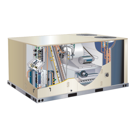
The KGC 7.5, 8.5, 10 and 12.5 ton (092, 102, 120, 150)
packaged gas units are available in standard cooling
efficiency. Units are available in 130,000, 180,000 or
240,000Btuh (38.1, 52.7 or 70.3 kW) heating inputs. Gas
heat sections are designed with aluminized steel tube
heat exchangers.
All KGC units are designed to accept any of several differ-
ent energy management thermostat control systems with
minimum field wiring. Factory- or field-provided control op-
tions connect to the unit with jack plugs. When "plugged
in" the controls become an integral part of the unit wiring.
Units come standard with a lightweight, all-aluminum con-
denser coil; optional, fin/tube condenser coils are avail-
able.
Information contained in this manual is intended for use
by qualified service technicians only. All specifications are
subject to change. Procedures outlined in this manual are
presented as a recommendation only and do not super-
sede or replace local or state codes.
If the unit must be lifted for service, rig unit by attaching
four cables to the holes located in the unit base rail (two
holes at each corner). Refer to the installation instructions
for the proper rigging technique.
WARNING
To prevent serious injury or death:
1- Lock-out/tag-out before performing maintenance.
2- If system power is required (e.g., smoke detector
maintenance), disable power to blower, remove
fan belt where applicable, and ensure all
controllers and thermostats are set to the "OFF"
position before performing maintenance.
3- Always keep hands, hair, clothing, jewelry, tools,
etc., away from moving parts.
WARNING
Improper
installation,
service or maintenance can cause property damage,
personal injury or loss of life. Installation and service
must be performed by a licensed professional HVAC
installer or equivalent, service agency, or the gas
supplier
UNIT INFORMATION
UNIT INFORMATION
KGC092 through 150
adjustment,
alteration,
100097
As with any mechanical equipment, contact with
sharp sheet metal edges can result in personal
injury. Take care while handling this equipment and
wear gloves and protective clothing.
Electric shock hazard. Can cause injury
or death. Before attempting to perform
any service or maintenance, turn the
electrical power to unit OFF at disconnect
switch(es). Unit may have multiple power
supplies.
Options . . . . . . . . . . . . . . . . . . . . . .Page 2
Specifications . . . . . . . . . . . . . . . . . .Page 5
Spec. Gas Heat / High Altitude . . . Page 9
Blower Data . . . . . . . . . . . . . . . . . . Page 7
Electrical Data. . . . . . . . . . . . . . . . . Page 11
I Unit Components . . . . . . . . . . . . . Page 14
II Placement and Installation . . . . . Page 27
III Start Up Operation . . . . . . . . . . . Page 27
IV Charging . . . . . . . . . . . . . . . . . . . Page 30
V System Service Checks . . . . . . . Page 36
VI Maintenance . . . . . . . . . . . . . . . . Page 38
VII Accessories . . . . . . . . . . . . . . . . Page 40
VIII Diagrams . . . . . . . . . . . . . . . . . . Page 48
Page 1
KGC SERIES
7.5 to 12.5 ton
CAUTION
WARNING
Table of Contents
Advertisement
Table of Contents

Related Manuals for Lennox KGC Series


Summary of Contents for Lennox KGC Series
-
Page 1: Table Of Contents
UNIT INFORMATION UNIT INFORMATION KGC SERIES 7.5 to 12.5 ton 100097 S e r v i c e L i t e r a t u r e KGC092 through 150 The KGC 7.5, 8.5, 10 and 12.5 ton (092, 102, 120, 150) packaged gas units are available in standard cooling efficiency. -
Page 2: Options
OPT IONS / A C C ESSORIES Unit Model No Catalog Item Description Number 092 102 120 COOLING SYSTEM Condensate Drain Trap 22H54 Copper 76W27 Conventional Fin/Tube Condenser Coil Factory (replaces Environ™ Coil System) (Required for Humiditrol Dehumidification option) ® Drain Pan Overflow Switch 74W42 Low Ambient Kit (0°F) - Page 3 OPT IONS / A C C ESSORIES Unit Model No Catalog Item Description Number 092 102 120 CONTROLS NOTE - Also see Conventional Thermostat Control Systems on page 13 for additional options. 11K76 Smoke Detector - Supply or Return (Power board and one sensor) Smoke Detector - Supply and Return (Power board and two sensors) 11K80 INDOOR AIR QUALITY...
- Page 4 OPT IONS / A C C ESSORIES Unit Model No Catalog Item Description Number 092 102 120 ECONOMIZER Standard Economizer (Not for Title 24) Standard Economizer with Single Temperature Control 13U45 Downflow or Horizontal Applications - Includes Barometric Relief Dampers and Air Hoods Standard Economizer Controls (Not for Title 24) Single Enthalpy Control 21Z09...
-
Page 5: Specifications
SP ECIF ICATIONS U NIT General Data Nominal Tonnage 7.5 Ton 8.5 Ton 10 Ton 12.5 Ton Model Number KGC092S4M KGC102S4M KGC120S4M KGC150S4M Efficiency Type Standard Standard Standard Standard Blower Type MSAV® MSAV® MSAV® MSAV® Multi-Stage Multi-Stage Multi-Stage Multi-Stage Air Volume Air Volume Air Volume Air Volume... - Page 6 SP EC IFIC ATIONS GA S HEAT Heat Input Type Standard Medium High Number of Gas Heat Stages Gas Heating Input - Btuh 1st Stage 84,500 117,000 156,000 Performance 2nd Stage 130,000 180,000 240,000 Output - Btuh 2nd Stage 104,000 144,000 194,000 Temperature Rise Range - °F...
-
Page 7: Blower Data
BLOWER DATA BELT D R IVE - 7 .5 | 8 .5 TO N KGC092S4M AND KGC102S4M - BASE UNIT BLOWER TABLE INCLUDES RESISTANCE FOR BASE UNIT ONLY (NO HEAT SECTION) WITH DRY INDOOR COIL AND AIR FILTERS IN PLACE. FOR ALL UNITS ADD: 1 −... - Page 8 BLOWER D ATA B ELT DR IVE - 1 0 | 1 2 .5 TO N KGC120S4M AND KGC150S4M - BASE UNIT BLOWER TABLE INCLUDES RESISTANCE FOR BASE UNIT ONLY (NO HEAT SECTION) WITH DRY INDOOR COIL AND AIR FILTERS IN PLACE. FOR ALL UNITS ADD: 1 −...
- Page 9 BLO WER DATA FACTORY INSTALLED BELT DRIVE KIT SPECIFICATIONS Nominal Maximum Drive Kit Number RPM Range 590 - 890 800 - 1105 795 - 1195 3.45 730 - 970 3.45 940 - 1200 3.45 1015 - 1300 5.75 900 - 1135 5.75 1040 - 1315 5.75...
- Page 10 BLO WER DATA CEILING DIFFUSERS AIR RESISTANCE - in. w.g. RTD11 Step-Down Diffuser FD11 Flush Air Volume 1 Side, 2 Ends All Ends & Sides Diffuser Unit Size 2 Ends Open Open Open 2400 0.21 0.18 0.15 0.14 2600 0.24 0.21 0.18 0.17...
-
Page 11: Electrical Data
ELECTRIC AL DATA 7.5 TO N Model No. KGC092S4 Voltage - 60Hz 208/230V - 3 Ph 460V - 3 Ph 575V - 3 Ph Compressor 1 Rated Load Amps (Non-Inverter) Locked Rotor Amps Compressor 2 Rated Load Amps (Non-Inverter) Locked Rotor Amps 36.5 Outdoor Fan Full Load Amps (2 Non-ECM) - Page 12 ELECTRIC AL DATA 10 TO N Model No. KGC120S4 Voltage - 60Hz 208/230V - 3 Ph 460V - 3 Ph 575V - 3 Ph Compressor 1 Rated Load Amps (Non-Inverter) Locked Rotor Amps Compressor 2 Rated Load Amps (Non-Inverter) Locked Rotor Amps 38.9 Outdoor Fan Full Load Amps (2 Non-ECM)
- Page 13 Parts Arrangement REHEAT EVAPORATOR BLOWER FILTERS COIL BLOWER CONDENSER COIL MOTOR (FOUR - 20 X 25 X 2”) FANS ECONOMIZER CONDENSER (OPTIONAL, BEHIND COIL PANEL) BURNERS COMBUSTION AIR INDUCER GAS VALVE INVERTER CONDENSATE COMPRESSORS DRAIN FIGURE 1 KGC Control Box Y, G, J Volt Units TB13 K265 K125...
-
Page 14: I Unit Components
I-UNIT COMPONENTS 4-Terminal Strip TB1 All indoor thermostat connections are made at terminal All 7.5 through 12.5 ton (26.3 through 44 kW) units are block TB1 located in the control area. For thermostats configure to order units (CTO). The KGC unit components without “occupied “... - Page 15 Plumbing and Refrigerant Circuit Detail Outdoor Coil Stage 1 (092 / 102) Outdoor Coil Stage 2 (120/150) Driers Outdoor Coil Stage 1 (120/150 Suction Line Outdoor Coil Discharge Line Stage 2 (092 / 102 Discharge Line Compressor 2 Compressor 1 COMPRESSOR 2 COMPRESSOR 1 S8 THERMAL...
- Page 16 KGC WITH OPTIONAL REHEAT KGC092 - 150 Shown Evaporator Coil Reversing Valve Reheat Coil (bottom) FIGURE 6 B-Cooling Components KGC150 Evaporators use a thermostatic expansion valve as primary refrigerant metering device. KGC092/102/120 All units use independent cooling circuits consisting of use thermostatic expansion valve on stage one and separate compressors, condenser coils and evaporator orifices on stage 2.
- Page 17 1-Compressors B1 and B2 To prevent coil icing, freezestats open during compressor operation to temporarily disable the respective compressor All units use two scroll compressors. Compressor capacity until the coil temperature rises. may vary from stage to stage. In all cases, the capacity of each compressor is added to reach the total capacity If the freezestats are tripping frequently due to coil icing, of the unit.
- Page 18 C-Blower Compartment 2 - Suction pressure must drop, discharge pressure must rise, and blower rotation must match rotation NOTE - Units equipped a Variable Frequency Drive (VFD) marking. are designed to operate on balanced, three-phase power. 3 - Disconnect all remote electrical power supplies. Operating units on unbalanced three-phase power will re- 4 - Reverse any two field-installed wires connected to duce the reliability of all electrical components in the unit.
- Page 19 STANDARD BLOWER ASSEMBLY SIDE VIEW TO INCREASE BELT TENSION 1- Loosen four bolts securing motor mounting base to frame. 2- Turn adjusting bolt to the right, or clockwise, to MOTOR ALLEN move the motor away from the blower housing. SCREW IMPORTANT - Gap between end of frame and motor PULLEY allel along gap.
- Page 20 LOCATION OF STATIC PRESSURE READINGS INSTALLATIONS WITH DUCTWORK INSTALLATIONS WITH CEILING DIFFUSERS ROOFTOP UNIT ROOFTOP UNIT RETURN AIR READING LOCATION RETURN AIR READING LOCATION SUPPLY SUPPLY TURN TURN FIRST BRANCH OFF OF MAIN RUN MAIN DUCT RUN SUPPLY AIR SUPPLY AIR READING READING DIFFUSER...
- Page 21 TABLE 2 MANUFACTURER’S NUMBERS DRIVE COMPONENTS DRIVE NO. ADJUSTABLE SHEAVE FIXED SHEAVE BELT BROWNING NO. OEM PART NO. BROWNING NO. OEM PART NO. BROWNING NO. OEM PART NO. 1VP34x7/8 31K6901 AK61x1 100244-20 AX54 100245-25 1VP40x7/8 79J0301 AK59x1 31K6801 AX55 100245-26 1VP34x7/8 31K6901 AK46x1...
- Page 22 D-GAS HEAT COMPONENTS 2-Burner Box Assembly (FIGURE 12) KGC units are available in 130,000 BTUH (38.1 kW), The burner assembly consists of a spark electrode, 180,000 BTUH (52.7 Kw) or 240,000 BTUH (70.3 kW) flame sensing electrode and gas valve. Ignition board A3 heat sizes.
- Page 23 3-Flame Rollout Limits S47 TABLE 3 Flame rollout limit S47 is a SPST N.C. high temperature S18 Prove Switch Settings limits located just above the burner air intake opening Close“ wc (Pa) Close“ wc (Pa) in the burner enclosures (FIGURE 12). S47 is wired to 0.25 + 5 (62.3+12.4) 0.10+5 (24.8+12.4) the ignition control A3.
- Page 24 8-Gas Valves GV1 NOTE - IN ORDER TO MAXIMIZE SPARK ENERGY Gas valve GV1 is a two-stage redundant valve. Units are- TO ELECTRODE, HIGH-VOLTAGE WIRE SHOULD equipped with valves manufactured by White-Rodgers TOUCH UNIT CABINET AS LITTLE AS POSSIBLE. orHoneywell. On a call for first-stage heat (low fire), the IMPORTANT valve is energized by the ignition control simultaneously with the spark electrode.
- Page 25 INTEGRATED CONTROL BOARD A3 TABLE 6 11-Burner Control A3 P2 TERMINAL DESIGNATIONS WARNING Function PIN # R 24 Volts to thermostat Electric shock hazard. Can cause injury W1 Heat Demand or death. Before attempting to perform any service or maintenance, turn the Y Cool Demand electrical power to unit OFF at disconnect C Common...
- Page 26 Flame rectification sensing is used on all KGC units. Loss IGNITION CONTROL A3 of flame during a heating cycle is indicated by an absence of flame signal (0 microamps). If this happens, the control will immediately restart the ignition sequence and then lock out if ignition is not gained after the third trial.
-
Page 27: Placement And Installation
II-PLACEMENT AND INSTALLATION BEFORE LIGHTING smell all around the appliance area for gas. Be sure to smell next to the floor because some Make sure the unit is installed in accordance with the gas is heavier than air and will settle on the floor. installation instructions and all applicable codes. - Page 28 C-Placing Unit In Operation 7 - Turn gas valve switch to ON. See FIGURE 18. On Honeywell VR8305Q gas valves, turn the knob on WARNING the gas valve counter clockwise to “ON”. Do not force. See FIGURE 19. Danger of explosion and fire. Can cause 8 - Close or replace the heat section access panel.
- Page 29 2 - No Economizer Installed in Unit - REFRIGERANT STAGES - 092, 102, 120, 150 See table 8 for cooling operation. CONDENSER COIL Units Equipped With Economizer - KG/KC 092, 102 - Stage 1 When outdoor suitable, KG/KC 120, 150 - Stage 2 combination thermostat demands...
-
Page 30: Charging
IV-CHARGING 3 - Measure the outdoor ambient temperature and the suction pressure. Refer to the appropriate A-All Aluminum Outdoor Coil circuit charging curve to determine a target liquid WARNING temperature. NOTE - Pressures are listed for sea level Refrigerant can be harmful if it is inhaled. Refrigerant applications. - Page 31 TABLE 10 581125-01 KG/KC 092S Normal Operating Pressures - All-Aluminum Coil Outdoor Coil Entering Air Temperature 65°F 75°F 85°F 95°F 105°F 115°F Suct Disc Suct Disc Suct Disc Suct Disc Suct Disc Suct Disc (psig) (psig) (psig) (psig) (psig) (psig) (psig) (psig) (psig)
- Page 32 TABLE 11 581126-01 KG/KC 102S Normal Operating Pressures - All-Aluminum Coil Outdoor Coil Entering Air Temperature 65°F 75°F 85°F 95°F 105°F 115°F Suct Disc Suct Disc Suct Disc Suct Disc Suct Disc Suct Disc (psig) (psig) (psig) (psig) (psig) (psig) (psig) (psig) (psig)
- Page 33 TABLE 12 581127-01 KG/KC 120S Normal Operating Pressures - All-Aluminum Coil Outdoor Coil Entering Air Temperature 65°F 75°F 85°F 95°F 105°F 115°F Suct Disc Suct Disc Suct Disc Suct Disc Suct Disc Suct Disc (psig) (psig) (psig) (psig) (psig) (psig) (psig) (psig) (psig)
- Page 34 TABLE 13 581128-01 KG/KC 150S Normal Operating Pressures - All-Aluminum Coil Outdoor Coil Entering Air Temperature 65°F 75°F 85°F 95°F 105°F 115°F Suct Disc Suct Disc Suct Disc Suct Disc Suct Disc Suct Disc (psig) (psig) (psig) (psig) (psig) (psig) (psig) (psig) (psig)
- Page 35 B-Refrigerant Charge and Check - Fin/Tube Coil 6 - If discharge pressure is high, remove refrigerant from the system. If discharge pressure is low, add WARNING - Do not exceed nameplate charge under refrigerant to the system. any condition. This unit is factory charged and should require no further •...
- Page 36 Charge Verification - Approach Method - AHRI Testing TABLE 16 581131-01 (Fin/Tube Coil Continued) KGC/KCC120S Fin/Tube - W & W/O Reheat 1 - Using the same thermometer, compare liquid tem- Outdoor CIRCUIT 1 CIRCUIT 2 perature to outdoor ambient temperature. Coil Discharge Suction +...
-
Page 37: System Service Checks
V- SYSTEMS SERVICE CHECKS 3-Testing Gas Supply Pressure When testing gas supply pressure, connect test gauge to A-Heating System Service Checks the inlet pressure tap located on unit gas valve GV1. Test All KGC units are ETL / CSA design certified without supply gas pressure with unit firing at maximum rate (both modification. - Page 38 5-High Altitude 8-Flame Sensing See table of contents for “High Altitude Derate” section for Flame current is an electrical current which passes from altitudes above 2000 feet (610 m). the ignition control through the sensor electrode during unit operation. The current passes from the sensor through 6-Proper Gas Flow the flame to the ground electrode (located on the flame Furnace should operate at least 5 minutes before checking...
-
Page 39: Maintenance
VI-MAINTENANCE 4 - Locate the ignitor under the left burners. Check ignitor spark gap with appropriately sized twist drills WARNING or feeler gauges. See FIGURE 25 and TABLE 20.. Electric shock hazard. Can cause injury 5 - Check the alignment of the ignitor and the sensor or death. - Page 40 IGNITOR AND SENSOR POSITION TOP VIEW Gas Flow Gas Flow 1-3/4” 1-3/8” (45mm) (35mm) 13/16” 3/8” (21mm) (10mm) BURNER BOX FIGURE 26 D-Combustion Air Inducer 4 - Clean inducer wheel blades with a small brush and wipe off any dust from housing. Clean accumulated A combustion air proving switch checks combustion dust from front of flue box cover air inducer operation before allowing power to the gas...
- Page 41 E-Flue Passageway and Flue Box (Gas Units) C-C1CURB Mounting Frames When installing units on a combustible surface for downflow 1 - Remove combustion air inducer assembly as de- discharge applications, the C1CURB roof mounting frame scribed in section D. is used. The roof mounting frames are recommended in 2 - Remove flue box cover.
- Page 42 D-Transitions An IAQ sensor is used when demand control ventilation (DCV) is specified. Damper minimum position can be set Optional supply/return transition C1DIFF30B-1, lower than traditional minimum air requirements resulting C1DIFF31B-1 and C1DIFF32B-1 are available for use in cost savings. The IAQ sensor allows the A6 to open with the KGC 7.5 through 12.5 ton units, utilizing optional dampers to traditional ventilation requirements as room C1CURB roof mounting frames.
- Page 43 C1DAMP20B MOTORIZED OUTDOOR AIR DAMPER MOTORIZED DAMPER COVER PANEL HORIZONTAL SUPPLY AIR OPENING COMPRESSOR HORIZONTAL SECTION RETURN AIR OPENING LOWER PANEL C1 DAMP10B MANUAL OUTDOOR AIR DAMPER COVER PANEL MANUAL DAMPER HORIZONTAL SUPPLY AIR OPENING COMPRESSOR HORIZONTAL SECTION RETURN AIR OPENING LOWER PANEL FIGURE 32...
- Page 44 TABLE 22 A6 ENTHALPY CONTROLLER ENTHALPY FREE COOLING SETPOINTS Control Setting Enthalpy Setpoint At 50% RH 73° F (23° C) MUM POSITION 70° F (21° C) 67° F (19° C) 63° F (17° C) IAQ MAXIMUM POSITION Open *Setting A is recommended (set higher than Damper Minimum Position minimum position)
- Page 45 CHART 1 CALCULATE MINIMUM FRESH AIR PERCENTAGE MIXED AND RETURN AIR TEMPERATURE OUTDOOR AIR TEMPERATURE FIGURE 34 DCV Set and Max Settings During the occupied time period dampers will open to DCV MAX when IAQ reading is above setpoint (regardless of Adjust settings when an optional IAQ sensor is thermostat demand or outdoor air suitability).
- Page 46 TABLE 23 ECONOMIZER OPERATION-OUTDOOR AIR IS SUITABLE FOR FREE COOLING -- FREE COOL LED “ON” Damper Position Thermostat Demand Mechanical Cooling Unoccupied Occupied Closed Closed Closed Minimum Modulating Modulating Modulating Modulating Stage 1 Modulating Modulating Stage 2 TABLE 24 ECONOMIZER OPERATION-OUTDOOR AIR IS NOT SUITABLE FOR FREE COOLING -- FREE COOL LED “OFF” Damper Position Thermostat Demand Mechanical Cooling...
- Page 47 J-Power Exhaust Fan A6 ENTHALPY CONTROLLER The power exhaust fan (PEF) requires the use of a gravity exhaust damper and economizer and is used in downflow ADJUST POWER applications only. See FIGURE 38. The PEF provides EXHAUST FAN exhaust air pressure relief and also runs when return air SETPOINT dampers are closed and the supply air blower is operating.
- Page 48 N-Hot Gas Reheat Start-Up and Operation 1 - Make sure reheat is wired as shown in wiring section. General 2 - Initiate a dehumidification demand by adjusting Hot gas reheat units provide a dehumidifying mode of dehumidistat setpoint knob BELOW indoor operation.
- Page 49 VIII-Wiring Diagrams and Sequence of Operation Page 49...
- Page 50 Sequence of Operation Power: 1st Stage Cooling (compressor B1) 1 - Line voltage from unit disconnect energizes 5 - First stage cooling demand Y1 and G are energized transformer T1. T1 provides 24VAC power to by the thermostat. G energizes blower. 24VAC is terminal strip TB1.
- Page 51 2 J229 P229 P229 J229 J229 P229 IGNITOR-SPARK COMBUSTION AIR BLOWER VESTIBULE HEATER,CONTROL 1 HEATING - GAS Page 51...
- Page 52 GAS HEAT SEQUENCE OF OPERATION First Stage Heat: End of Second Stage Heat: 1 - The thermostat initiates W1 heating demand. 9 - Heating demand is satisfied. Terminal W2 (high fire) is de-energized. 2 - 24VAC is routed from TB1 to ignition control A3 through P2.
- Page 53 ELECTRONIC OR ELECTROMECHANICAL THERMOSTAT Page 53...
- Page 54 ELECTRONIC OR ELECTROMECHANICAL THERMOSTAT Page 54...
- Page 55 ELECTRONIC OR ELECTROMECHANICAL THERMOSTAT A183 USED ON UNITS WITH VFD ONLY Page 55...
-
Page 56: Accessories
ECONOMIZER (POL224) AUX2- AUX2- AUX1- AUX1- RT26 AUX- RT27 S-COM S-24V 0-10 24VAC ACT- BLACK COMMON 2-10 GRAY ACT2-10 ACT- PINK ACT-FB ACT- COMPONENT CONTROL - ECONOMIZER SENSOR - OUTDOOR ENTHALPY OUTDOOR AIR TEMP SENSOR RT26 OR OUTDOOR AIR SENSOR - INDOOR ENTHALPY ENTHALPY SENSOR A7 MAY BE USED.
Need help?
Do you have a question about the KGC Series and is the answer not in the manual?
Questions and answers