Shelly Wave 1PM Extended User Manual
Z-wave smart switch with power measurements
Hide thumbs
Also See for Wave 1PM:
- Quick start manual ,
- Extended user manual (30 pages) ,
- User and safety manuallines (2 pages)
Table of Contents
Advertisement
Quick Links
Advertisement
Table of Contents

Related Manuals for Shelly Wave 1PM


Summary of Contents for Shelly Wave 1PM
- Page 1 Wave 1PM Z-Wave™ smart switch with power measurements Extended User Guide (EN) Device: Wave 1PM Part number EU: QNSW-001P16EU Z-Wave Product type ID: 0x0002 Z-Wave Product ID: 0x0084 Z-Wave Manufacturer: Allterco Z-Wave Manufacturer ID: 0x0460...
-
Page 2: Table Of Contents
Table of contents 1. Terminology and Abbreviations....................4 2. About Shelly Qubino ........................ 4 3. About the Device ........................4 4. Electrical diagrams (110-240 V AC / 24-30 V DC) ..............5 4.1 Installation instruction ......................6 5. About Z-Wave™ ........................8 6. - Page 3 Parameter No. 23 - O (O1) contact type - NO/NC ..............18 Parameter No. 25 - Set timer units to s or ms for O (O1) ............. 19 Parameter No. 36 - O (O1) Power report on change - percentage ........19 Parameter No.
-
Page 4: Terminology And Abbreviations
1. Terminology and Abbreviations • Device - In this document, the term “Device” is used to refer to the Shelly Qubino device that is a subject of this guide. • Gateway (GW) - A Z-Wave™ gateway, also referred to as a Z-Wave™ controller, Z-Wave™... -
Page 5: Electrical Diagrams (110-240 V Ac / 24-30 V Dc)
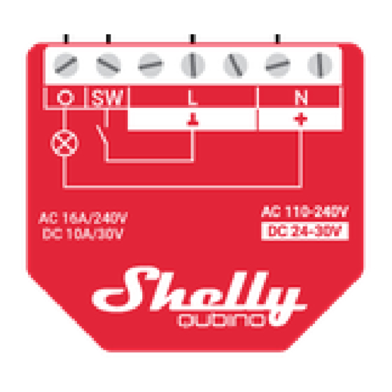
in the Device settings, each press of the push-button will change the output O (O1) state to the opposite state - on, off, on, etc. 4. Electrical diagrams (110-240 V AC / 24-30 V DC) Connecting to the power grid with power supply 110-240 V AC (Fig. 1), or 24-30 V DC (Fig. 2). Fig. -
Page 6: Installation Instruction
L: Live wire (110-240 V AC) +: 24 - 30 V DC positive wire GND: 24 - 30 V DC ground wire Button: S: S button 4.1 Installation instructions The Device can control a various type of loads (e.g., bulbs) in one electrical circuit (up to 16 A) and measures power consumption of the connected device (AC only). - Page 7 ⚠CAUTION! Use only one phase AC circuit. Do not use mixed AC and DC circuits. ⚠CAUTION! Do not allow children to play with the push-buttons/ switches connected to the Device. Keep the devices for remote control of Shelly Qubino (mobile phones, tablets, PCs) away from children.
-
Page 8: About Z-Wave
5. About Z-Wave™ The Z-Wave™ protocol is an interoperable, wireless, RF-based communications technology designed specifically for control, monitoring, and status reading applications in residential and light commercial environments. Mature, proven, and broadly deployed, Z-Wave™ is by far the world market leader in wireless control, bringing affordable, reliable, and easy-to-use 'smart' products to millions of people in every aspect of daily life. -
Page 9: Z-Wave™ Adding / Removing / Factory Reset
6. Z-Wave™ Adding / Removing / Factory reset 6.1 Adding the Device to a Z-Wave™ network (inclusion) Note! All Device outputs (O, O1, O2, etc. - depending on the Device type) will turn the load 1s on/1s off /1s on/1s off if the Device is successfully added to/removed from a Z-Wave™ network. Note! In case of Security 2 (S2) adding (inclusion), a dialog will appear asking you to enter the corresponding PIN Code (5 underlined digits) that are written on the Z-Wave™... -
Page 10: 3Adding (Inclusion) With The S Button
6. The green LED will be blinking in Mode 1 if the Device is successfully added to a Z- Wave™ network. *Learn mode - a state that allows the Device to receive network information from the gateway. 6.1.3 Adding (inclusion) with the S button 1. -
Page 11: Removing (Exclusion) With The S Button
6. The blue LED will be blinking in Mode 1 if the Device is successfully removed from a Z- Wave™ network. 6.2.2 Removing (exclusion) with the S button 1. Connect the Device to a power supply. 2. Check if the green LED is blinking in Mode 1. If so, the Device is added to a Z-Wave™ network. -
Page 12: Remote Factory Reset With Parameter With The Gateway
1. To enter the Setting mode, quickly press and hold the S button on the Device until the LED turns solid blue. 2. Press the S button multiple times until the LED turns solid red. 3. Press and hold (> 2s) S button on the Device until the red LED starts blinking in Mode 3. Releasing the S button will start the factory reset. -
Page 13: Z-Wave™ Security 2 And Device Specific Key (Dsk)
7. Z-Wave™ Security 2 and Device Specific Key (DSK) The Device supports the latest Security 2 (S2) feature. S2 is handled by the strong AES 128 Encryption protocol, which means that the S2 makes Z-Wave™ the most secure IoT (Internet of Things) security platform out there. - Page 14 ⓘ NOTE: This Device must be used in conjunction with a Security Enabled Z-Wave gateway to fully utilize all implemented functions. ⓘ NOTE: This Device is a security enabled Z-Wave Plus™ product that can use encrypted Z- Wave Plus™ messages to communicate to other security enabled Z-Wave Plus™ products. ⓘ...
-
Page 15: Led Signalization
8. LED Signalization General rules • Switching between Normal and Settings mode is done by Single press on the S button • Solid LED means that you are in the Settings mode (this is not valid for Plugs). Once in settings mode, switch to normal mode goes automatically after 10s •... -
Page 17: Z-Wave™ Parameters
9. Z-Wave™ Parameters Parameter No. 1 - SW (SW1) Switch type This parameter defines how the Device should treat the switch (which type) connected to the SW (SW1) terminal. Value size: 1 Byte Default value: 2 Values & descriptions: • 0 - momentary switch, •... -
Page 18: Parameter No. 20 - O (O1) Auto On With Timer
• 1 - 32535 = 1 - 32535 seconds (or milliseconds – see Parameter no. 25. Auto OFF timer enabled for a given amount of seconds (or milliseconds) resolution 100ms Parameter No. 20 - O (O1) Auto ON with timer If the load O (O1) is OFF, you can schedule it to turn ON automatically after the period of time defined in this parameter. -
Page 19: Parameter No. 25 - Set Timer Units To S Or Ms For O (O1)
Parameter No. 25 - Set timer units to s or ms for O (O1) Set the timer units to seconds or milliseconds. Choose if you want to set the timer in seconds or milliseconds in Parameters No. 19, 20. Values size: 1 Byte Default value: 0 Values &... -
Page 20: Parameter No. 91 - Water Alarm
• 0 - reports are disabled • 1-120 (1-120s) - report interval NOTE: This Parameter is in relation to Parameter No. 36. NOTE: Setting the value to less than 30s can cause the Z-Wave network congestion state (slow Device response and decreased network stability). Parameter No. -
Page 21: Parameter No. 94 - Heat Alarm
Values size: 4 Byte Default value: 0 Values & descriptions: • 0 no action • 1 open relay • 2 close relay Parameter No. 94 - Heat Alarm This parameter determines which alarm frames the Device should respond to and how. The parameters consist of 4 bytes, the three most significant bytes are set according to the official Z-Wave protocol specification. -
Page 22: Parameter No. 201 - Serial Number 1
Parameter No. 201 - Serial Number 1 This parameter contains a part of device’s serial number. The parameter is Read-Only and cannot be changed. The parameter is Advanced and may be hidden under the Advanced tag. Values size: 4 Byte Default value: Device specific Values &... - Page 23 Default value: Device specific Values & descriptions: · 0x00000000 - 0x7FFFFFFF...
-
Page 24: Z-Wave™ Command Class
10. Z-Wave™ Command Class 1. ASSOCIATION_V2 [S0, S2]* 2. ASSOCIATION_GRP_INFO_V3 [S0, S2]* 3. BASIC_V2 [S0, S2]* 4. SWITCH_BINARY_V2 [S0, S2]* 5. CONFIGURATION_V4 [S0, S2]* 6. DEVICE_RESET_LOCALLY_V1 [S0, S2]* 7. FIRMWARE_UPDATE_MD_V5 [S0, S2]* 8. INDICATOR_V3 [S0, S2]* 9. MANUFACTURER_SPECIFIC_V2 [S0, S2]* 10. - Page 25 Switch (O) will be turned ON or OFF, after receiving the BASIC_SET command: Basic Command received Mapped Command (binary Switch) Basic Set (0xFF) Switch binary Switch (0xFF) Basic Set (0x00) Switch binary Switch (0x00) Basic GET Basic Report (Current Value, Target Value) Supporting Command Class Indicator The Device supports the Command Class Indicator V3 (ID 0x50).
-
Page 26: Z-Wave™ Notifications Command Class
11. Z-Wave™ Notifications Command class 11.1 Overheat detected Z-Wave Z-Wave Device Device Z-Wave Notification Notification colour Action to restore reaction specific definition Type Name Name status Any of the following activities reset this alarm: power cycle, notification Remote Device type=heat reboot (with Check alarm... -
Page 27: Ac Mains Disconnected
117), short Value=0x06, Version=V3 press on the S button, press on switch/push- button connected to any SW (SW, SW1, SW2, …) terminal. 11.3 AC mains disconnected Z-Wave Z-Wave LED colour Device Action to Device Z-Wave Notification Notification status reaction restore specific definition Type Name... -
Page 28: Z-Wave™ Associations
12. Z-Wave™ Associations Associations are used for direct communication between the Device and other devices within your Z-Wave network without the need of the Z-Wave gateway. Max. number of associated devices per group is 9. This value is fixed and cannot be configured. Each association group supports the association of up to 9 devices (nodes). -
Page 29: Supported Load Types
• BASIC_SET: set On / Off state at the associated device Root device - Association Group 3 Association Group 3 Allowed nodes: 9 It is assigned to switch connected to the SW (SW1) terminal (uses Switch Multilevel command class). Triggered by SW (SW1). It is recommended to use push buttons for this association. -
Page 30: Technical Specifications
14. Technical Specifications Power supply 110-240 V AC / 24–30 V DC Power consumption < 0.3 W Power measurement (W) Max switching voltage AC 240 V Max switching current AC 16 A Max switching voltage DC 30 V Max switching current DC 10 A Overheating protection Overload protection... - Page 31 Colour Ambient temperature -20°C to 40°C / -5°F to 105°F Humidity 30% to 70% RH Max. altitude 2000 m / 6562 ft.
-
Page 32: Important Disclaimer
16. Declaration of Conformity Hereby, Allterco Robotics EOOD declares that the radio equipment type Wave 1PM is in compliance with Directive 2014/53/ EU, 2014/35/EU, 2014/30/EU, 2011/65/EU. The full text of the EU declaration of conformity is available at the following internet address: https://shelly.link/Wave1PM-DoC...
Need help?
Do you have a question about the Wave 1PM and is the answer not in the manual?
Questions and answers