Table of Contents
Advertisement
Quick Links
使用说明书
电动螺丝刀
EYADA 系列
型号
EYADA212XC
EYADA218XC
EYADA407XC
重要信息
使用本产品之前, 请先详细阅读说明书, 并妥加保
管, 以便日后使用。
所在地区不供货的型号, 请参阅最新总目录。
原版说明书: 英文
原版说明书译本: 其他语言
目次
.......................................2
................................4
..............................10
..............................13
.....................................17
.................................22
(设置模式)
c +数字) ..................................25
(
u +数字) ..................................32
(
n +数字) ..................................39
(
b +数字) ..................................41
(
...................................49
...................................51
.....................................52
...........................54
............................................56
索引
使
用
前
准
备
操
作
....................44
其
他
CN
Advertisement
Chapters
Table of Contents

Related Manuals for Panasonic EYADA Series


Summary of Contents for Panasonic EYADA Series
-
Page 1: Table Of Contents
使用说明书 电动螺丝刀 目次 EYADA 系列 型号 使 EYADA212XC ........2 产品特点 用 ........4 安全注意事项 EYADA218XC 前 ......10 各部分的名称 EYADA407XC 准 备 ......13 使用前的准备 ........17 使用方法 设置主体的功能 .........22 (设置模式) 计数菜单 c +数字) ........25 ( 操 实用程序菜单 作 u +数字) ........32 ( 通知菜单 n +数字)... -
Page 2: 产品特点
产品特点 本产品是一款搭载无刷电机的电动螺丝刀, 具有轻便、 易握持 的特点。 本产品易于操作, 无需更换刷子, 具有良好的易维护性, 可让作 业变得更舒适。 ※ 无需控制器即可在本机内进行各种功能的设置。 ■ 请勿忘记紧固螺丝 P. 25 设置要进行紧固的螺丝数量。 ■ 想知道紧固状态 P. 20 、 21 设置判定指示灯。 ■ 想进行螺丝紧固合格与否判定 P. 35 设置旋转时间的上下限值。 ■ 想选择拉杆启动、 按压启动 P. 17 拉杆启动 按压启动 设置启动方式。 ■ 想减少工具的取错率 P. 42 PLC 等)... - Page 3 ■ 螺丝紧固中的主要支持功能 计数完成 紧固 OK 旋转开始 (计数完毕) 1 根 2 根 N 根 第 第 第 下限值设置 上限值设置 计数数量设置 P. 35 P. 25 使 用 前 判定无效设置 软启动设置 软着座设置 计数无效设置 计数完成判定待机时间设置 准 不可 P. 29 P. 32 P. 32 P. 30 P.
-
Page 4: 安全注意事项
安全注意事项 请务必遵守 为了防止对人的危害和财产的损害, 请必须遵守说明事项。 ■ 针对错误使用时产生的危害和损害程度进行区分并说明。 警 告 可能造成死亡或重伤的内容。 注意 可能造成轻伤或发生财产损害危险的内容。 ■ 使用以下图片符号表示必须遵守的内容。 (以下是图片符号的示例) 绝对禁止的内容。 必须执行的内容。 警 告 日常管理扭矩。 如不遵守, 将会因扭矩变动而造成螺丝松动, 引发事故。 中断作业时及不使用时, 确认没有运行。 更换钻头和配件时, 以及保管主体时, 请务必将正 / 反转扳手置于开 关锁定位置, 并拔出电源适配器的电源线。 如不遵守, 可能会因意外运行而引发事故。 使用过程中, 保持主体不动, 避免左右摆动。 否则可能会导致人员受伤。... - Page 5 用 前 作业场所要足够明亮。 昏暗会使视线变差, 从而导致事故或人员受伤。 加工物要牢固固定。 准 否则可能会发生意外移动, 导致人员受伤。 备 使用夹钳或虎钳等固定, 确保安全。 使用过程中, 如果主体使用状况变差, 或发出异音, 请立即关闭开关, 停止使用。 Panasonic 客户咨询中心。 如果继续使用, 将导 请咨询您所购买的销售店或 致人员受伤。 请按照使用说明书牢固安装钻头等尖头工具类及配件。 务必遵守 操 如未安装牢固, 可能会因脱落而导致人员受伤。 作 拆除用于调节的键及扳手等工具类后再使用。 如不遵守, 可能会因意外脱落而导致人员受伤。 穿着整洁的衣物进行作业。 • 请勿穿着宽松的衣物及佩戴项链等饰品, 否则可能会被卷入旋转部。...
- Page 6 安全注意事项 请务必遵守 警 告 使用时请勿超过插座和配线器具的额定值。 仅限在电气额定范围内 使用。 如果由于并联等方式超出额定值, 会因发热而引起火灾。 请勿损坏螺丝刀电源线、 电源线、 电源插头。 (不要损伤、 破坏、 加工、 靠近发热器具、 强行弯曲、 拧扭、 拉伸、 放置重物、 夹入、 捆扎) 如果在本产品损伤的情况下使用, 会造成触电、 短路、 火灾。 定期检查电线和插头, 如有破损, 请咨询销售商。 主体冒烟时, 请勿吸入烟气。 否则会对身体造成损害。 作业刚结束时, 请勿触摸钻头等尖头工具类和螺丝、 切屑。 否则会因高温而烫伤。 ...
- Page 7 警 告 不使用时, 将电源插头从插座中拔出。 如不遵守, 将会因绝缘老化而导致触电或漏电起火。 禁止 打雷后, 请勿触摸本产品及电源插头。 使 否则会触电。 用 前 禁止接触 不得改装。 且不可拆解或维修。 否则可能会引起火灾、 触电、 人员受伤。 准 维修事宜请咨询您所购买的销售店或本公司咨询窗口。 备 禁止拆解 请勿进行以下操作。 请勿在淋雨或潮湿场所使用或放置。 使用时不要浸入水中。 否则可能会出现冒烟、 起火、 破裂。 禁止淋水 请勿用湿手从插座中插拔电源插头。 操 作 否则可能会触电。 禁止湿手...
- Page 8 安全注意事项 请务必遵守 注 意 主体发烫时, 应中断作业, 待温度下降后再使用。 如不遵守, 可能会造成烫伤。 拔出电源插头时, 请务必握住电源插头拔出, 而不是拉扯电源线。 如果拉扯电源线拔出, 将会导致触电、 短路。 使用前, 请确认主体、 尖头工具和其他零件有无损伤, 是否能正常运 转。 如不遵守, 可能会因破损等而造成人员受伤。 请保持作业场所干净整齐。 务必遵守 场所和作业台散乱会引发事故。 充分注意操作、 作业方法及周围状况等, 以常识进行作业。 如不遵守, 可能会引发事故或导致人员受伤。 壁挂安装电源适配器时, 需用螺丝牢牢固定, 防止掉落。 否则可能会因掉落而导致人员受伤。 ...
- Page 9 注 意 请勿在不合理的姿势下作业。 否则可能会摔倒而受伤。 请时刻注意脚底, 保持平衡。 疲劳时请勿使用。 使 否则可能会引发事故或人员受伤。 用 前 请勿让儿童等非作业人员靠近车间或触碰主体。 禁止 否则可能会导致人员受伤。 准 备 请勿随身携带电线。 否则, 可能会因主体掉落导致人员受伤。 操 作 其 他...
-
Page 10: 各部分的名称
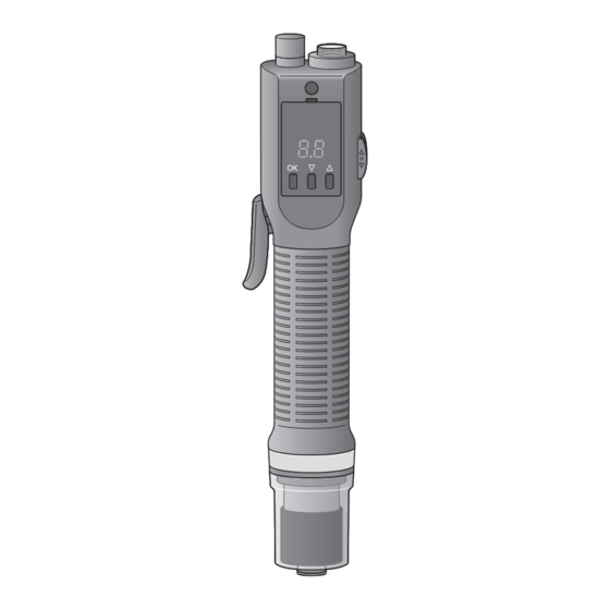
各部分的名称 主体 ■ 正面 ■ 侧面 ⑫ ⑬ ⑭ ③ ⑯ ② ① ③ ④ ⑪ ⑮ ⑤ ⑥ ⑦ ⑩ ⑧ ⑨ ① 螺丝刀电源线 ⑨ 钻套 (六角轴、 6.35 mm ) ② 通信电缆 ⑩ 联轴器盖 ③ 螺丝刀挂具安装孔 ⑪ 序列号牌 ④ 操作面板 ⑫... - Page 11 ■ 操作面板 Ⓐ 使 用 前 Ⓒ Ⓑ Ⓓ 准 备 Ⓐ 显示屏 Ⓒ ▲按钮 Ⓑ Ⓓ ▼按钮 OK 按钮 操 作 其 他...
- Page 12 各部分的名称 (续) 配 件 (不附带钻头) ■ ■ 螺丝刀挂具 ■ 联轴器盖 2 m 螺丝刀电源线 ■ 握柄附件 EYADA407XC 标配 ※ 仅 另 售 件 ■ 电源适配器 EYSZP001 ) ( [ 仅中国适用 ] [ 仅马来西亚适用 ] [ 仅泰国适用 ] 电源线 电源线 电源线 [ 仅印度尼西亚适用 ] [ 仅印度适用 ] 电源线...
-
Page 13: 使用前的准备
使用前的准备 / 反转扳手 使用正 安装螺丝刀挂具 / 反转扳手可以更改电动螺丝刀的 使用正 将螺丝刀挂具向两侧轻拉 旋转方向, 或锁定启动。 如用力拉螺丝刀挂具, 将无法复原。 请用安装、 拆卸所需的力度进行操作。 开关位置 旋转方向 放入螺丝刀挂具安装孔 反转 (左转) 螺丝刀挂具安装孔 ○ 开关锁定状态 使 正转 (右转) 用 前 螺丝刀挂具安装孔 准 备 将螺丝刀挂具向两侧轻拉。 R 位置 ○位置 F 位置 请按图中所示安装螺丝刀挂具和工 具平衡器。 工具平衡器 开关锁定... - Page 14 使用前的准备 (续) ■ 本机可安装的钻头 安装钻头 6.35 mm 要求 A B 安装、 拆卸钻头时, 请将正 / 反转扳手置 于 “○ (开关锁定状态) ” 的位置, 然后 球槽部 ※ 中央 关闭电源适配器的电源开关。 P. 13 、 16 ※ 不可使用不含球槽部的直钻头。 A 的长度 12 mm ~ 17.5 mm 拉伸钻套 (双头钻头)...
- Page 15 套件内容 安装握柄附件 ① 握柄附件 ( A ) … 1 个 所有机型均可安装。 ② 握柄附件 ( EYADA407XC 标配) B ) … 1 个 (仅 ③ 触发器 … 1 个 可阻断联轴器运转时的反作用力, 减轻疲 劳。 ④ 接头 … 1 个 ⑤ 螺丝 … 7 个 以拉杆启动方式使用时...
- Page 16 使用前的准备 (续) 将电源线安装到电源适配器 连接电源 要求 电源适配器 (另售件) 请将正 / 反转扳手置于 “○” 的位置, 锁 定开关后进行连接。 P. 13 请勿使用非本公司的电源 (螺丝刀电 源线、 电源适配器、 电源线) 。 此外, 请勿在其他设备上使用本公司专 用电源和电源线。 长期不使用时, 建议从插座中拔出电源 电源线 (另售件) 线。 即使未打开本产品电源, 也会消耗 电量。 确认电源适配器的电源开关已 将螺丝刀电源线连接到电源适 关闭 配器和本产品 OFF 时,...
-
Page 17: 使用方法
使用方法 ■ 切换为按压启动方式 切换启动方式 / 反转扳手设到 “○” 的 将正 2 种旋转启动方式。 本产品具有 请根据作业, 切换使用。 位置 (出厂时为拉杆启动方式) 变为开关锁定状态。 P. 13 ■ 切换为拉杆启动方式 将钻头前端按压到作业台等处 / 反转扳手设到 “○” 的 将正 5 秒) , 直至判定指示灯亮黄 (约 位置 1 秒) 灯 (约 变为开关锁定状态。 使 请在钻套部分微陷的状态下稍等片 用... - Page 18 使用方法 (续) 用联轴器手柄调节扭矩 通知 如下图所示, 可以拆除拉杆开关。 ① ② ① 要提高输出扭矩时, 将联轴器手柄向右 (顺时针) 转 ② 要降低输出扭矩时, 将联轴器手柄向左 拉杆开关固定 螺丝 (逆时针) 转 请遵守以下事项, 以确保不发生故障, 拉杆开关 长期安全地使用。 请在确认电源适配器的电源开关关 • 请参考紧固扭矩标准表设置扭矩。 闭后, 再拆卸拉杆开关。 P. 19 • 请勿在电机锁定时强行使用。 安装联轴器盖 设置紧固扭矩 请顺时针旋转联轴器盖。 96 档调节联轴器扭矩。 可根据作业, 按 ■...
- Page 19 紧固扭矩标准表 (参考值) 本数据是在以下测量条件下测得的参考值。 实际作业因周围条件 (螺丝、 零配件、 固定方法等) 而异。 使 用 前 EYADA407XC 紧 固 扭 矩 准 EYADA212XC 备 EYADA218XC 刻度 操 作 1 个刻度为 12 档 12 下) (点击 0 】 8 】...
- Page 20 使用方法 (续) 开始旋转 开始作业 如为 “拉杆启动” , 请拉动拉杆。 / 反转扳手设置旋转方向 用正 如为 “按压启动” , 请朝钻头方向按 F ” 位置为正转 (右转) , 设到 设到 “ 压。 R ” 位置为反转 (左转) 。 “ 拉杆启动 按压启动 R 位置 F 位置 启动时, 旋转初期可能会有一瞬间变 慢, 这并非故障。 ...
- Page 21 ■ 计数完成 (计数完毕) 结束作业 OK 的螺丝紧固达到设定的计 判定为紧固 / 反转扳手设为开关锁定 数数量的状态。 将正 - ) 和判定指示灯亮蓝灯通 通过蜂鸣器 (哔 请设到 “○” 位置。 知螺丝紧固已经正常执行完设置次数。 • 请设置计数数量。 P. 25 • 可在菜单中更改指示灯的亮灯颜色。 P. 39 • 可在菜单中更改蜂鸣器模式。 P. 39 • 可在菜单中更改蜂鸣器音量。 P. 40 使 用 ○位置 判定指示灯 前...
-
Page 22: 设置主体的功能
设置主体的功能 (设置模式) 1. 切换为设置模式 可根据作业更改本产品设置。 更改设置时, 请切换为设置模式。 ■ 返回作业模式 作业模式 设置模式 在设置模式中 (判定指示灯闪烁 OK 按钮 黄灯) 长按 3 声短音 (哔哔哔) , 判定 蜂鸣器鸣响 指示灯熄灭。 判定指示灯 判定指示灯 熄灭 闪烁黄灯 ■ 切换为设置模式 / 反转扳手设为开关锁定 将正 哔哔哔 请设到 “○” 位置。 OK 按钮 长按 / 反转扳手... - Page 23 u +数字) 至实用程序菜单 ( ■ 通知菜单 ( n +数字) ■ 计数菜单 ( c +数字) 显示 内容 参照页 显示 内容 参照页 指示灯亮灯颜色设置 计数数量设置 蜂鸣器模式设置 使 计数方式设置 用 指示灯亮灯模式设置 前 计数返回设置 蜂鸣器音量设置 数量复位的许可设置 准 备 判定无效设置 ■ 实用程序菜单 ( u +数字) 显示 内容...
- Page 24 设置主体的功能 (设置模式) (续) 主体复位 (初始化设置) 将主体的设置恢复为厂家出厂时的状态。 b4 主体复位的许可 启用本功能时, 请将 “ 1 ” 。 设置” 设为 “_ P. 43 ■ 设置步骤 切换为设置模式 / 反转扳手设为开关锁定, 长 请将正 OK 按钮。 按 详情见 P. 22 OK 按钮、 ▼按钮、 ▲ 同时长按 按钮 - ) , 显示屏显示 蜂鸣器长鸣...
-
Page 25: 计数菜单 C +数字
c +数字) 计数菜单 ( 计数数量设置 3 ” 时 设置要进行螺丝紧固的数量。 设为 “ OK 的螺丝紧固进行计数, 达到设 对紧固 置的数量后, 会通过蜂鸣器和点亮判定指 示灯进行通知。 哔 哔 哔 P. 20 、 21 • 作业模式时, 在主体的显示屏上显示计数 亮绿灯 亮绿灯 亮蓝灯 数量。 使 • 达到设置的数量后, 会复位显示屏上的计 用 数。 前 1 根 2 根... - Page 26 c +数字) 计数菜单 ( (续) 计数方式设置 可切换螺丝紧固数量的计数方式。 倒数方式 正数方式 1 、 2 … 3 、 2 … ■ 设置步骤 OK 按钮确定 按 切换为设置模式 - ) , 显示 设置完成后, 蜂鸣器长鸣 (哔 / 反转扳手设为开关锁定, 长 请将正 屏返回菜单显示。 OK 按钮。 按 P. 22 返回作业模式...
- Page 27 计数返回设置 OK 的螺丝紧固进行 1 ” 时 可设置对紧固 设为 “_ 重新操作、 拧松等反转作业时的计数 处理。 计数退回 1 个 重新操作 2 根 第 使 (反转) 用 前 准 ■ 设置步骤 备 1 根螺丝的状态下, 即使 ※ 在未紧固任何 切换为设置模式 反转, 计数也不会恢复为超过初始值。 / 反转扳手设为开关锁定, 长 请将正 ※ 在设定的计数数量的最后数量执行反转 OK 按钮。...
- Page 28 c +数字) 计数菜单 ( (续) 数量复位的许可设置 1 ” 时 许可手动复位计数数量。 设为 “_ 1 ” , 无需等待在计数数量设 如果设为 “_ 置中指定的数量, 同时长按▼按钮和▲按 钮即可复位计数。 计数恢复为 初始值 执行手动复位 ■ 设置步骤 OK 按钮确定 按 切换为设置模式 - ) , 显示 设置完成后, 蜂鸣器长鸣 (哔 / 反转扳手设为开关锁定, 长 请将正...
- Page 29 判定无效设置 0.3 ” 时 可将短时间空转及设置按压启动时对准 设为 “ 螺丝孔等与作业无关的意外旋转排除在 判定之外。 请设置排除在判定之外的旋转时间。 判定无效 使 用 0.3 秒以内的旋转 前 0.3 秒以内的旋转排除在紧固判定之外 将 准 ■ 设置步骤 备 OK 按钮确定 按 切换为设置模式 - ) , 显示 设置完成后, 蜂鸣器长鸣 (哔 / 反转扳手设为开关锁定, 长 请将正 屏返回菜单显示。 OK 按钮。 按...
- Page 30 c +数字) 计数菜单 ( (续) 计数无效设置 OK 后, 可设置为即使进行二次紧固 紧固 紧固 也不计数。 OK 后, 请设置排除在计数之外的紧 紧固 计数 固时间。 无效 在设置时间内 • 重新操作或拧松等反转作业的计数有效。 执行紧固 • “ 计数无效设置” 和 “ 作业禁止设 置” 有效时, 优先 “ 作业禁止设置” 。 P. 37 OK 后, 设为计数无效的时间在二次紧固后 紧固...
- Page 31 计数完成判定待机时间设置 3.0 ” 时 设为 “ 可设置最终数量的螺丝紧固变为紧固 后, 到计数完成 (计数完毕) 判定的待机时 间。 设置的待机时间可按照设置的计数数量 的最终数量执行反转作业。 • 在待机时间内无法进行正转作业。 3.0 秒反转 使 可进行 用 作业 前 OK 后, 可以 3.0 秒不进行计 按最终数量紧固 数, 执行松开等重新操作的反转作业。 准 ■ 设置步骤 备 OK 按钮确定 按 切换为设置模式 - ) , 显示 设置完成后,...
-
Page 32: 实用程序菜单 U +数字
u +数字) 实用程序菜单 ( 软启动、 软着座时间设置 可设置软启动的持续时间和软着座的开始时间。 软启动 软着座 时间 u2 软启动转速等级设置” 中设置软启 请在 “ 时间 u3 软着座转速等级设置” 中 动时的转速, 在 “ 设置软着座时的转速。 P. 33 、 34 • 软着座开始时间不可设为小于软启动持续时间。 作业中 作业开始 紧固 (旋转中) 什么是软着座 什么是软启动 钻头在着座前缓慢旋转, 以减少偏离和对基 开始紧固螺丝时缓慢旋转, 以防出现拧 倾, 螺丝卡阻。 材的影响。... - Page 33 软启动转速等级设置 04 ” 时 可设置软启动的转速。 设为 “ u1 软启动、 软着座时间设置” 中设 请在 “ 置软启动的持续时间。 P. 32 • 由于电机结构的原因, 从软启动转速提升 软启动中设置的时间 到通常转速时, 会发生时间滞后。 以最大转速约 的转速缓慢紧固 使 用 前 准 ■ 设置步骤 备 按▲▼按钮进行设置 切换为设置模式 10 ” 。 初始值为 “ / 反转扳手设为开关锁定, 长 请将正...
- Page 34 u +数字) 实用程序菜单 ( (续) 软着座转速等级设置 04 ” 时 可设置软着座的转速。 设为 “ u1 软启动、 软着座时间设置” 中设 请在 “ 置软着座的开始时间。 P. 32 • 由于电机结构的原因, 从通常转速下降到 软着座中设置的时间 软着座转速时会发生时间滞后。 以最大转速约 的转速缓慢紧固 ■ 设置步骤 按▲▼按钮进行设置 切换为设置模式 10 ” 。 初始值为 “ / 反转扳手设为开关锁定, 长 请将正...
- Page 35 按旋转时间的判定设置 0.3 、 上限值 0.6 时 可通过螺丝紧固的旋转时间判定紧固 设置为下限值 情况。 OK 的紧固时间的上下 请设置达到紧固 限值。 紧固 NG 紧固 NG 紧固 u7 秒表模式” 下测量最佳旋转 可在 “ ( NOK ) ( NOK ) 时间。 P. 38 使 以 0.1 秒着座 以 0.5 秒着座 以 0.8 秒着座 •...
- Page 36 u +数字) 实用程序菜单 ( (续) 旋转自动停止设置 1 ” 时 可按设置的时间自动停止旋转。 设为 “_ u4 按旋转时间的判定设置” 中, 在不着座而停止的攻丝工序中, 和因取错 ※ 在 “ 螺丝而导致长螺丝贯穿零部件的工序中 上限值设为 有效。 • 请在 “ 按旋转时间的判定设置” 中设 置旋转时间的上限值。 旋转 P. 35 停止 • 当到达旋转时间的上限值时, 将不进行联 螺丝紧固 轴器运转而停止旋转动作。 不进行螺丝紧 启动 固判定,...
- Page 37 作业禁止设置 OK 后, 在设置时间内不 可设置为紧固 紧固 启动。 • “ 计数无效设置” 和 “ 作业禁止 钻头不转 设置” 有效时, “ 作业禁止设置” 优先。 P. 30 在设置时间内 执行紧固 使 用 OK 后, 电动螺丝刀在作业禁止设置中设 紧固 前 置的时间内不启动。 准 备 ■ 设置步骤 OK 按钮确定 按 切换为设置模式 - ) , 显示 设置完成后,...
- Page 38 u +数字) 实用程序菜单 ( (续) 秒表模式 可测量螺丝紧固的旋转时间的最大值、 在秒表模式下, 显示屏显示螺丝紧固 最小值。 由于螺丝的长度及旋转速度 时间 (秒) 。 不同, 测量值会存在偏差, 因此请进行多 次测量。 • 在秒表模式下, 不进行紧固判定。 • 即使在秒表模式中, 也可设置实用程序 菜单。 在秒表模式中, 判定指示灯 • 退出秒表模式时, 请重新设置为 “_ _” 。 闪烁浅蓝色 (蓝绿色) 秒表模式中的操作 ▲按钮: 显示旋转时间的最大值 长按▲按钮: 复位最大值、 最小值 ▼按钮:...
-
Page 39: 通知菜单 N +数字
n +数字) 通知菜单 ( 指示灯亮灯颜色设置 蜂鸣器模式设置 可设置判定指示灯的亮灯颜色。 可设置计数完成 (计数完毕) 时的蜂鸣 器模式。 ■ 设置步骤 ■ 设置步骤 切换为设置模式 切换为设置模式 使 / 反转扳手设为开关锁定, 长 / 反转扳手设为开关锁定, 长 请将正 请将正 用 OK 按钮。 OK 按钮。 前 按 按 P. 22 P. 22 n1 ” , 再按 n2 ”... - Page 40 n +数字) 通知菜单 ( (续) 指示灯亮灯模式设置 蜂鸣器音量设置 NG ( NOK ) 时及发生错误 可设置紧固 可设置蜂鸣器音量。 OK 时的确认音和操作音的通用 时, 判定指示灯的亮灯模式。 ※ 紧固 设置。 ■ 设置步骤 ■ 设置步骤 切换为设置模式 切换为设置模式 / 反转扳手设为开关锁定, 长 / 反转扳手设为开关锁定, 长 请将正 请将正 OK 按钮。 OK 按钮。 按 按...
- Page 41 b +数字) 基本设置菜单 ( 制动器设置 外部输出时的信号设置 可设置联轴器运转前的旋转停止时有 可从 “计数完成信号” 和 “紧固 NOK ) 信号” 中选择外部输出信号。 无制动器。 ( P. 45 ■ 设置步骤 ■ 设置步骤 切换为设置模式 切换为设置模式 使 / 反转扳手设为开关锁定, 长 / 反转扳手设为开关锁定, 长 请将正 请将正 用 OK 按钮。 OK 按钮。 前 按...
-
Page 42: 基本设置菜单 B +数字
b +数字) 基本设置菜单 ( (续) ■ 设置步骤 外部输入时的驱动许可设置 切换为设置模式 使用通信电缆连接外部设备时, 可从外 / 反转扳手设为开关锁定, 长 请将正 部设备控制本产品。 P. 44 OK 按钮。 按 在使用多个工具的作业中, 通过仅许可 P. 22 作业工具启动, 或确保不许可的工具不 b3 ” , 再按 启动, 防止取错工具。 按▲▼按钮, 选择 “ 此外, 还可切换控制中的电动螺丝刀的 OK 按钮 / 熄灭。... - Page 43 ■ 设置步骤 主体复位的许可设置 切换为设置模式 许可主体复位。 / 反转扳手设为开关锁定, 长 请将正 1 ” 后, 在设置模式下同时长 OK 按钮。 设置为 “_ 按 OK 按钮、 ▼按钮和▲按钮, 可将工具 按 P. 22 初始化。 b4 ” , 再按 P. 24 按▲▼按钮, 选择 “ OK 按钮 1 ” 时 设为...
-
Page 44: 通信电缆的使用方法
通信电缆的使用方法 PLC 等外部设 连接另售的通信电缆, 可与 安装通信电缆 备进行数据收发。 拆下连接器盖 插拔电缆时, 请将电源适配器的电源开关 OFF 后再进行。 置于 连接器盖 确认连接器的方向, 切实安装到 底 将电缆捆扎好, 以防通信电缆 断线 连接外部设备和通信电缆时, 请仔细阅读 外部设备的使用说明书。... - Page 45 输入输出信号 线色 输入输出 信号名 备注 OK 时输出。 紧固 OK 信号 红 输出 紧固 0.5 秒) (固定为 使 NG ( NOK ) 时输出。 用 紧固 NG ( NOK ) 信号 紧固 前 0.5 秒) (固定为 蓝 输出 设置的计数数量完成时输出。 准 计数完成信号 0.5 秒) (固定为...
- Page 46 通信电缆的使用方法 (续) 信号时间 作业实例 N=1/2 N=1/2 • 以 2 根完成作业 联轴器运转 联轴器运转 • 在松开作业中插入 1 次 紧固 (正转) 紧固 (正转) 松开 (反转) 电机正转信号 电机反转信号 c7 计数完成判定待机 “ P. 31 时间设置” OK 信号 紧固 0.5 秒 0.5 秒 NG ( NOK ) 紧固...
- Page 47 内部电路图 PLC 内部 主体内部 外部电源 24 V OK 信号 红色: 紧固 使 NG ( NOK ) 信号 蓝色: 紧固 用 计数完成信号 前 黄色: 电机正转信号 准 备 紫色: 电机反转信号 绿色: 驱动许可信号 4.7 k Ω 浅蓝色: 操 作 其 他...
- Page 48 通信电缆的使用方法 (续) 通知 ■ 输入电路 • 光耦合器输入电路。 • 请在 DC24 V ± 10% 下使用。 • 消耗电流为一次输入约 5 mA 。 ■ 输出电路 • 集电极开路电路。 • 请在 DC24 V ± 10% 下使用。 • 最大输出电流为一次输出 20 mA 。 ■ 输入输出电路 • 绝对最大额定值为电压 30 V 、 电流 20 mA 。 ...
-
Page 49: 性能、 规格
性能、 规格 主体性能 EYADA212XC EYADA218XC EYADA407XC 型号 小螺丝: 小螺丝: 小螺丝: 建议作业 M2.5 ~ M4.5 M2.5 ~ M4 M3.5 ~ M5 0.3 N ・ m ~ 2.5 N ・ m 0.3 N ・ m ~ 2.0 N ・ m 1.5 N ・ m ~ 4.4 N ・ m 扭矩设置范围... - Page 50 性能、 规格 (续) 数量计数时的设置 • 计数方式 • 计数返回 • 计数复位 • 判定无效 • 计数无效 • 计数完成判定待机 螺丝紧固合格与否 / 下限设置) 可以 (旋转时间的上限 判定 • 软启动 螺丝紧固支持 • 软着座 • 作业禁止设置 • 旋转自动停止 PLC 侧设置) 时序控制 可以 (需要在 其他 秒表模式 • 旋转方向切换 (正转 / 反转)...
-
Page 51: 维护、 保管
维护、 保管 维护 保管 ■ 用软布擦拭 ■ 请避免以下条件进行保管 从插座中拔出电源插头, 然后从主体拆下 • 车内等高温场所 螺丝刀电源线, 用干燥的软布擦拭。 • 阳光直射的场所 请勿使用湿布、 稀释液、 苯、 酒精等挥发性 • 有水和潮湿等的场所 物品。 • 垃圾和粉尘多的场所 (否则会造成变色、 变形、 开裂) • 儿童可以触及的场所 • 有汽油等易燃物的场所 使 • 有掉落危险的场所 用 前 ■ 实施定期检查 • 请定期检查螺丝是否存在松动、 破损、 动作 准... -
Page 52: 错误显示
错误显示 如有异常, 主体的显示屏会闪烁错误标记。 请进行以下检查及处理。 • “ E0 ” ~ “ E7 ” : OK 按钮, 错误显示消失。 按下 • “ EE ” 及 “ F2 ” ~ “ Fb ” : OK 按钮, 或者通过操作开关, 错误显示即会消失。 按下 如果处理后仍有异常, 请立即停止使用。 请将产品携至您所购买的销售店。 显示 可能的原因 处理... - Page 53 ■ 作业中发生时的错误显示 显示 可能的原因 处理 这并非产品异常。 在紧固作业中, 联轴器运 请让主体动作, 直至联轴器运 转之前主体停止。 转。 这并非产品异常。 使 在紧固作业中, 超过了旋 用 请确认工件及旋转时间的设 转时间的上限、 下限值范 前 定值。 围。 P. 35 准 / 反 / 反 在紧固作业中更改正 请勿在紧固作业中操作正 备 转扳手。 转扳手。 请消除发生过载的条件, 重新 在紧固作业中, 发生过 进行确认。 载、...
-
Page 54: 设置模式一览表
设置模式一览表 c 系 count ( 与数量计数相关的设置) -- 1 根 P. 25 计数数量设置 P. 26 计数方式设置 _ 倒数方式 _ _ 1 个 P. 27 计数返回设置 _ 退回 _ _ P. 28 数量复位的许可设置 不许可 _ 许可 - . - 0.1 秒 P. 29 判定无效设置... - Page 55 ~ 2 根 99 根 _ 正数方式 _ 恢复为初始值 ~ 0.2 秒 9.9 秒 ~ 0.2 秒 9.9 秒 使 用 ~ 前 0.2 秒 9.9 秒 ~ 0.2 秒 9.9 秒 准 备 Level 10 Level 2 ~ 33 %) (约为最大时的...
- Page 56 索引 安装螺丝刀挂具……………………… 计数完成 (计数完毕) ……………… 安装通信电缆………………………… 计数完成 (计数完毕) 后重新执行 作业时 …………………………… 安装握柄附件………………………… NG ( NOK ) …………………… 21 紧固 安装钻头……………………………… OK ……………………………… 20 紧固 按设置时间自动停止旋转…………… OK 后, 避免在二次紧固时计数 紧固 按压启动方式………………………… …………………………………… OK 后, 设置为在设置时间内不启动 紧固 …………………………………… 测量螺丝紧固的旋转时间…………… OK 后重新执行作业时 ………… 27 紧固...
- Page 57 软启动………………………………… 许可主体复位………………………… 软着座………………………………… 选择外部输出的信号………………… 设置发生异常时的判定指示灯亮灯 因意外旋转而无法计数……………… 模式 ……………………………… 设置计数完成 (计数完毕) 时的蜂鸣器 使 32–34 着座前缓慢旋转………………… 模式 ……………………………… 用 前 正数方式……………………………… 设置计数完成 (计数完毕) 时的蜂鸣器 音量 ……………………………… 13, 20 正转……………………………… 设置紧固扭矩………………………… 准 设置进行螺丝紧固的数量…………… 备 设置判定指示灯的亮灯颜色………… 设置软启动时的转速………………… 设置软着座时的转速………………… 设置外部输入时的驱动许可………… 设置旋转的制动器…………………… / 反转扳手 …………………… 13 使用正...
- Page 58 [ 中国大陆 ] 产品中有害物质的名称及含量 有毒有害物质或元素 部件名称 6 价铬 多溴联苯 多溴二苯醚 (Pb) (Hg) (Cd) 铅 汞 镉 (Cr(VI)) (PBB) (PBDE) 外壳 ○ ○ ○ ○ ○ ○ 回路基板 × ○ ○ ○ ○ ○ 马达 ○ ○ ○ ○ ○ ○ 其他付属品...
- Page 59 Operating Instructions Electric Screwdriver Table of Contents EYADA Series Model No.: FEATURES OF PRODUCT ... 2 EYADA212XC SAFETY PRECAUTIONS ..... 4 EYADA218XC NAMES OF PARTS ..... 10 EYADA407XC PREPARATION BEFORE USE .. 13 HOW TO USE ......17 SETTING FUNCTIONS OF TOOL (SETTING MODE) .......
-
Page 60: Features Of Product
FEATURES OF PRODUCT This unit is a compact and easy-to-grip Electric Screwdriver equipped with a brushless motor. It handles well and is very easy to maintain because there is no need to replace a brush, thereby providing a comfortable working experience. * You can make function settings on this unit without a controller. - Page 61 ■ Support functions helpful for screw fastening Count-up Rotation start Fastening OK (Count complete) 1st screw 2nd screw Nst screw Lower Limit Upper Limit Count Quantity Setting Setting Setting P. 35 P. 25 Ignore Judgement Ignore Count Time Batch Complete Judgement Soft Start Setting Soft Snug Setting Time Setting...
-
Page 62: Safety Precautions
SAFETY PRECAUTIONS Always adhere to the instructions Below are the instructions you should always adhere to, to prevent human harm and property damage. ■ The severity of harm and damage caused by incorrect use is presented with the following. WARNING May cause death or serious injury. - Page 63 If the tool malfunctions or makes abnormal noises during use, immediately turn off the trigger switch and stop using it. Consult your dealer or Panasonic Customer Support Centre. Using it as is may result in injury. Following the Operating Instructions, attach a bit or other pointed tools, and accessories securely.
- Page 64 SAFETY PRECAUTIONS Always adhere to the instructions WARNING Do not use a socket or wiring device in the manner of exceeding the rated value. Use only within electrical rated range. Exceeding the rated value due to an overloaded socket may cause heat generation resulting in fire.
- Page 65 WARNING Disconnect the power plug between uses. Failure to observe this may cause poor insulation resulting in electric shock or fire from electric leakage. Prohibited If it is thundering, do not touch this unit or the power plug. Failure to observe this may result in electric shock.
- Page 66 SAFETY PRECAUTIONS Always adhere to the instructions CAUTION If the tool becomes hot, interrupt the work and wait for it to cool down before use. Failure to observe this may cause burns. To disconnect the power plug, always hold the power plug without pulling the cord.
- Page 67 CAUTION Do not work in an unusual position. Otherwise you may fall over and be injured. Always stand on a stable footing and keep a good balance. Do not use the tool when you are tired. Failure to observe this may cause an accident or injury. ...
-
Page 68: Names Of Parts
NAMES OF PARTS Tool ■ Front View ■ Side View ⑫ ⑬ ⑭ ③ ⑯ ② ① ③ ④ ⑪ ⑮ ⑤ ⑥ ⑦ ⑩ ⑧ ⑨ ① Screwdriver cord ⑨ Bit holder (for hex shaft, 6.35 mm) ② Communication cable ⑩... - Page 69 ■ Operation panel Ⓐ Ⓒ Ⓑ Ⓓ Ⓐ Display Ⓒ ▲ button Ⓑ OK button Ⓓ ▼ button...
- Page 70 NAMES OF PARTS (cont.) Accessories (No bit is supplied.) ■ 2 m Screwdriver Cord ■ Screwdriver Hanger ■ Clutch Cover ■ Grip Attachment * Supplied for EYADA407XC only Separately sold items ■ Power Adapter (EYSZP001) [For China only] [For Malaysia only] [For Thailand only] Power Cord 1 m Power Cord 1 m...
-
Page 71: Preparation Before Use
PREPARATION BEFORE USE Using Forward/Reverse Lever Attaching Screwdriver Hanger With the forward/reverse lever, you Pull the screwdriver hanger can change the rotation direction of the lightly on both sides. Electric Screwdriver or lock the start. Pulling the screwdriver hanger hard Trigger may prevent it from returning to its switch... - Page 72 PREPARATION BEFORE USE (cont.) ■ Bits That Can Be Attached to This Attaching Bit Unit ATTENTION 6.35 mm A B When attaching or removing a bit, set the forward/reverse lever to the “○ (Trigger switch locked)” position, and turn OFF the power Ball groove section* Centre switch of the power adapter.
- Page 73 Attaching Grip Attachment Components of the attachment ① Grip attachment (A) x 1 The grip attachment can be attached to ② Grip attachment (B) x 1 all models. (Supplied for EYADA407XC only) ③ Trigger x 1 It can absorb the reactive force during ④...
- Page 74 PREPARATION BEFORE USE (cont.) Connecting to Power Supply Attach the power cord to the power adapter. ATTENTION Power adapter Before connection, set the forward/ (sold separately) reverse lever to the “○” position to lock the trigger switch. P. 13 ...
-
Page 75: How To Use
HOW TO USE ■ Switching to Push Start Mode Switching Start Modes Set the forward/reverse This unit has two modes for rotation lever to the “○” position. start. The trigger switch gets locked. Switch them according to the work P. 13 before use. - Page 76 HOW TO USE (cont.) Adjust the torque with the NOTE clutch handle. The lever trigger switch can be ① ② removed as shown in the following figure. ① To increase the output torque, turn the clutch handle clockwise. ② To decrease the output torque, turn the clutch handle anticlockwise.
- Page 77 Recommended Fastening Torque Chart (Reference Values) These data are reference values measured under the following measurement conditions. In actual work, they vary depending on the surrounding conditions (such as screws, materials, and fixing methods). EYADA407XC EYADA212XC EYADA218XC ...
- Page 78 HOW TO USE (cont.) Starting Work Start rotation. In “lever start” mode, pull the lever. Set the rotation direction In “push start” mode, push toward with the forward/reverse the bit. lever. Lever start Push start When you set it to the “F” position and the “R”...
- Page 79 ■ Count-up (Count finished) Finishing Work The number of fastened screws Set the forward/reverse determined as OK has reached the set lever to the trigger switch count quantity. With a buzzer (a long beep) and the blue lock position. detection lamp, you are notified that the Set it to the “○”...
-
Page 80: Setting Functions Of Tool (Setting Mode)
SETTING FUNCTIONS OF TOOL (SETTING MODE) 1. Switching to Setting Mode This unit can change settings according to the work. To change settings, switch to setting mode. ■ Back to Operation Mode Operation mode Setting mode Hold down the OK button while you are in setting mode (the detection lamp is blinking yellow). - Page 81 To Utility Menu (u + Number) ■ Notification Menu (n + Number) ■ Count Menu (c + Number) Reference Display Description page Reference Display Description page Lamp Lighting Count Quantity Colour Setting Setting Buzzer Pattern Setting Count Method Setting Lamp Lighting Pattern Setting Count Return Setting...
- Page 82 SETTING FUNCTIONS OF TOOL (SETTING MODE) (cont.) Tool Reset (Initialisation Setting) Put the tool settings back to the manufacturer default settings. To enable this function, set “ b4 Tool Reset Permission Setting” to “_1”. P. 43 ■ Setting Procedure Switch to setting mode. Set the forward/reverse lever to the trigger switch lock position, and hold down the OK button.
-
Page 83: Count Menu (C + Number)
COUNT MENU (c + NUMBER) Count Quantity Setting The number of screws to fasten is set. When it is set to “3” The number of fastened screws determined as OK is counted, and when A short A long it reaches the set quantity, you are A short beep beep... - Page 84 COUNT MENU (c + NUMBER) (cont.) Count Method Setting You can switch count methods for Count-down mode Count-up mode screw fastening. 1, 2… 3, 2… ■ Setting Procedure Switch to setting mode. Press the OK button to Set the forward/reverse lever to confirm it.
- Page 85 Count Return Setting You can set how fastened screws When it is set to “_1” determined as OK are counted when reversing rotations to redo or loosen them. The count goes back by one. The 2nd screw is redone. (Reverse rotations) ■...
- Page 86 COUNT MENU (c + NUMBER) (cont.) Quantity Reset Permission Setting A manual reset of the count quantity is When it is set to “_1” permitted. When it is set to “_1”, you can reset the count by holding down the ▼ and ▲...
- Page 87 Ignore Judgement Time Setting You can exclude unexpected rotations When it is set to “0.3” that are unrelated to work, such as brief idling and screw hole alignment in push start mode, from detection. Ignore Set the duration of rotations to exclude Judgement from detection.
- Page 88 COUNT MENU (c + NUMBER) (cont.) Ignore Count Time Setting You can set screws not to be counted Fastening OK even if they are fastened again after being determined as OK. Set the duration of fastening to exclude Count ignored from counting after fastening is Fastening is determined as OK.
- Page 89 Batch Complete Judgement Waiting Time Setting When it is set to “3.0” You can set the waiting time from when the last screw fastening is determined as OK to when it is determined as count-up (count complete). During the set waiting time, you can reverse rotations after finishing the last screw set in the count quantity.
-
Page 90: Utility Menu (U + Number)
UTILITY MENU (u + NUMBER) Soft Start & Soft Snug Time Setting The duration of soft start and the start time of soft snug can be set. Soft snug Soft start time time The speed of soft start and the speed of soft snug should be set in “... - Page 91 Soft Start Speed Level Setting The speed of soft start can be set. When it is set to “04” The duration of soft start should be set in “ u1 Soft Start & Soft Snug Time Setting”. P. 32 • Because of the structure of the motor, During the time set it requires some time to increase the in soft start, a screw...
- Page 92 UTILITY MENU (u + NUMBER) (cont.) Soft Snug Speed Level Setting The speed of soft snug can be set. When it is set to “04” The start time of soft snug should be set in “ u1 Soft Start & Soft Snug Time Setting”.
- Page 93 Rotation Time-based Detection Setting You can determine whether or not a When the lower limit and the upper limit screw is properly fastened based on the are set to 0.3 and 0.6 respectively rotation time taken to fasten the screw. Set the lower and upper limits for the fastening time to be determined as OK.
- Page 94 UTILITY MENU (u + NUMBER) (cont.) Automatic Rotation Stop Setting Rotation can be stopped automatically When it is set to “_1” after the set time has passed. * The upper limit is set to 0.6 in “ This is effective in a process where it Rotation Time-based Detection is necessary to stop rotation without Setting”.
- Page 95 Disable Fastening Time Setting You can set the tool not to start Fastening OK during the set time after fastening is determined as OK. • When both the “ The bit Ignore Count does not Time Setting” and the “ Disable rotate.
- Page 96 UTILITY MENU (u + NUMBER) (cont.) Stopwatch Mode You can measure the maximum and In stopwatch mode, the screw fastening minimum values of the rotation time time (in seconds) is displayed on the of screw fastening. Perform several display. measurements because there are variations in the measured values due to screw length and rotation speed.
-
Page 97: Notification Menu (N + Number)
NOTIFICATION MENU (n + NUMBER) Lamp Lighting Colour Setting Buzzer Pattern Setting You can set the lighting colour of the You can set the buzzer pattern for detection lamp. count-up (count complete). ■ Setting Procedure ■ Setting Procedure Switch to setting mode. Switch to setting mode. - Page 98 NOTIFICATION MENU (n + NUMBER) (cont.) Lamp Lighting Pattern Setting Buzzer (Volume) Setting You can set the lighting pattern of You can set the buzzer (volume). the detection lamp for fastening NG * This is a common setting for the (NOK) and error occurrence.
-
Page 99: Basic Setting Menu (B + Number)
BASIC SETTING MENU (b + NUMBER) Brake Setting External-Output Signal Setting You can enable or disable braking You can select “Count-up signal” or when rotation stops before clutch “Fastening NG (NOK) signal”, as the activation. external output signal. P. 45 ■... - Page 100 BASIC SETTING MENU (b + NUMBER) (cont.) ■ Setting Procedure External-Input Drive Permission Setting Switch to setting mode. When connected to an external Set the forward/reverse lever to device with a communication cable, the trigger switch lock position, and this unit can be controlled from the hold down the OK button.
- Page 101 ■ Setting Procedure Tool Reset Permission Setting Switch to setting mode. A tool reset is permitted. Set the forward/reverse lever to the trigger switch lock position, and When you set it to “_1”, you can hold down the OK button. P.
-
Page 102: How To Use Communication Cable
HOW TO USE COMMUNICATION CABLE Attaching Communication Cable By connecting a separately sold communication cable, you can perform data transmission and reception with Remove the connector cap. external devices such as PLC. When connecting or disconnecting the cable, turn OFF the power switch of the power adapter. - Page 103 Input/Output Signals Wire Input/ Signal name Remark colour Output Output when fastening is OK. Output Fastening OK signal (Fixed for 0.5 s) Fastening NG (NOK) Output when fastening is NG (NOK). signal (Fixed for 0.5 s) Blue Output Output when the set count quantity is Count-up signal completed.
- Page 104 HOW TO USE COMMUNICATION CABLE (cont.) Signal Timing Example of actual N = 1/2 N = 1/2 work Clutch activation Clutch activation • Work completed with Fastening Fastening two screws. (Forward) (Forward) • Loosening is inserted Loosening once in between. (Reverse) Motor forward signal...
- Page 105 Internal Circuit Diagrams Inside of tool Inside of PLC External power supply 24 V Red: Fastening OK signal Blue: Fastening NG (NOK) signal Count-up signal Yellow: Motor forward signal Purple: Motor reverse signal Green: Drive permission signal 4.7 kΩ Light blue: COM...
- Page 106 HOW TO USE COMMUNICATION CABLE (cont.) Information ■ Input circuit • It is a photocoupler input circuit. • The voltage must be 24 V DC ± 10%. • It consumes a current of approximately 5 mA per input. ■ Output circuit •...
-
Page 107: Capacity And Specifications
CAPACITY AND SPECIFICATIONS Tool Capacity Model No. EYADA212XC EYADA218XC EYADA407XC Machine screw: Machine screw: Machine screw: Recommended Work M3.5 to M5 M2.5 to M4.5 M2.5 to M4 Torque Setting Range 0.3 N ・ m to 2.5 N ・ m 0.3 N ・ m to 2.0 N ・ m 1.5 N ・... - Page 108 CAPACITY AND SPECIFICATIONS (cont.) Notification (Lamp) 5-colour display (Detection lamp) Notification (Buzzer) 3 steps of volume • Count method Settings for Quantity • Count return Count • Count reset • Ignore judgement time • Ignore Count Time • Batch complete judgement waiting time Screw Fastening Possible (Rotation time upper/lower limit setting) Quality Determination...
-
Page 109: Cleaning And Storage
CLEANING AND STORAGE Cleaning Storage ■ Wiping with Soft Cloth ■ Avoid the following conditions during storage. Disconnect the power plug from the outlet, remove the screwdriver cord from • Car cabin or other hot places the tool, and then wipe it with dry soft •... -
Page 110: Error Codes
ERROR CODES If there is any problem, an error code blinks on the display of the tool. Consult the table below and take a necessary action. • [E0] to [E7] Pressing the OK button will clear the error display. • [EE] and [F2] to [Fb]: Press the OK button. - Page 111 ■ Error codes for errors that occur during work. Display Possible cause Action During a fastening Nothing is wrong with the process, the tool was product. stopped before the Keep the tool in action until clutch activated. the clutch activates. During a fastening Nothing is wrong with the process, the rotation time...
-
Page 112: Setting Mode List
SETTING MODE LIST c series count (Settings related to quantity count) - - Count Quantity Setting 1 screw P. 25 _1 Count Method Setting Count-down mode P. 26 _ _ _1 Count Return Setting P. 27 Return 1 count Quantity Reset Permission Setting _... - Page 113 ~ 2 screws 99 screws _2 Count-up mode _2 Return to start ~ 0.2 s 9.9 s ~ 0.2 s 9.9 s ~ 0.2 s 9.9 s ~ 0.2 s 9.9 s Level 2 Level 10 ~ (About 33% of maximum) (Maximum speed) Level 2 Level 10...
-
Page 114: Index
INDEX Attaching Bit ........14 Lever Start Mode ........ 17 Attaching Communication Cable ..44 Attaching Grip Attachment ....15 Making Rotation Stop Automatically after Set Attaching Screwdriver Hanger .... 13 Time Has Passed ......36 Manually Resetting Count ....28 Changing Count Method..... - Page 115 Setting Buzzer (Volume) for Count-up (Count Complete) ..40 Trigger Switch Lock ......13 Setting Buzzer Pattern for Count-up (Count Complete) ..39 Using Forward/Reverse Lever .... 13 Setting Drive Permission for External Input ........ 42 Setting Fastening Torque ....18 When Connecting to PLC ....
- Page 116 −MEMO−...
- Page 117 −MEMO−...
- Page 118 −MEMO−...
- Page 119 Panasonic service center when disposing of this product. Customer care number (Toll free) : 1800 103 1333 ,1800 105 1333 Please see the Panasonic website for further information on collection centers, etc. or call the customer care toll-free number https://www.panasonic.com/in/corporate/e-waste-management.html...
- Page 120 [中国大陆] 松下住宅电器 (上海) 有限公司 上海市松江工业区江田东路 258 号 Panasonic 客户咨询电话 :4008-209-376 Panasonic Corporation https://panasonic.cn 1006, Oaza Kadoma, Kadoma-shi, Osaka 571-8501, Japan https://www.panasonic.com CN, EN EY9310ADA202 2023.12 S 2023 年 12 月 发行: 中国印刷...
Need help?
Do you have a question about the EYADA Series and is the answer not in the manual?
Questions and answers