Table of Contents
Advertisement
Quick Links
Download this manual
See also:
Service Manual
Advertisement
Table of Contents

Related Manuals for Yamaha DA824


Summary of Contents for Yamaha DA824
- Page 1 DA CONVERTER Owner’s Manual PEAK NOMINAL SIGNAL Keep This Manual For Future Reference. PEAK LOCK POWER NOMINAL SIGNAL DA CONVERTER...
-
Page 2: Important Information
設置されるとき EIA 標準のラックにこの機器をマウントす ● る場合は、ラックの背面を開放して、ラッ クを壁から 10cm 以上離す。また、 パワー ア ンプ など の発 熱し やす い機 器と いっ しょにラックにマウントする場合は、機器 と機器の間を空けたり通風パネルなどを 取り付けたり、この機器に熱がこもらない ようにする。 その場合は、この機器を重ねてマウントで きます。放熱が不十分だと機器内部に熱が こもり、故障や火災の原因になることがあ ります。 U.R.G., Pro Audio & Digital Musical Instrument Division, Yamaha Corporation © 2004 Yamaha Corporation... - Page 3 300 ohm ribbon lead, change the lead-in to coaxial type cable. If these corrective measures do not produce satisfactory results, please contact the local retailer authorized to distribute this type of product. If you can not locate the appropriate retailer, please contact Yamaha Corporation of America, Electronic Service Division, 6600 Orangethorpe Ave, Buena Park, CA 90620 The above statements apply ONLY to those products distributed by Yamaha Corporation of America or its subsidiaries.
- Page 4 • Do not subject the DA824 to extreme temperatures, humidity, direct sunlight, or dust, which could be a potential fire or electrical shock hazard. • Do not allow water to enter the DA824 or allow it to become wet. Fire or electrical shock may result.
-
Page 5: Package Contents
• Turn off audio devices when connecting them to the DA824, and use only the cables specified in the relevant owner’s manuals. • If you plan not to use the DA824 for a long period of time, remove the power cord from the AC outlet. Leaving the DA824 connected is a potential fire hazard. - Page 6 Copyright No part of the DA824 software or this Owner’s Manual may be reproduced or distrib- uted in any form or by any means without the prior written authorization of Yamaha Corporation.
-
Page 7: Table Of Contents
Turning On the Power ..........1 2 Touring the DA824 ......2 Front Panel . -
Page 8: Introduction
DA824 (at least 10 cm of free space behind). If the DA824 is mounted in a portable rack case, keep the rear of the case open when using the DA824, so as not to obstruct the flow of air from the air vents. Do not mount the DA824 next to equipment that produces a lot of heat, such as a power amplifier. -
Page 9: Touring The Da824
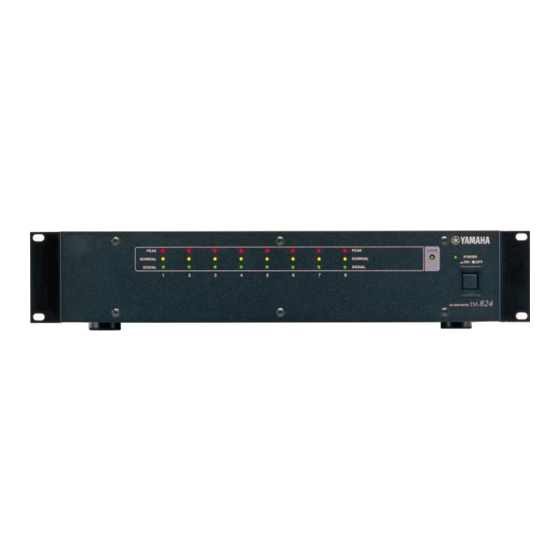
This indicator lights up when the DA824 is powered up. POWER switch This switch is used to turn on the power to the DA824. It’s recessed to prevent accidental operation. See “Turning On the Power” on page 1 for more information. -
Page 10: Rear Panel
MODEL DA824 THRU SLOT COM port This port is for updating the DA824’s internal firmware and is not used in normal oper- ation. WORD CLOCK THRU connector This BNC connector transmits the wordclock signal received at the WORD CLOCK IN. -
Page 11: Digital I/O Cards
3 Digital I/O Cards About Digital I/O Cards For digital input, the DA824 uses optional mini YGDAI (Yamaha General Digital Audio Interface) cards, which are available in all the popular digital audio interconnect for- mats, including AES/EBU, ADAT, and Tascam TDIF-1. -
Page 12: Installing I/O Cards
Keep the cover and fixing screws in a safe place for future use. Insert the card between the guide rails and slide it all the way into the slot, as shown below. You may have to push firmly to plug the card into the DA824 connector. -
Page 13: Hookup Examples
4 Hookup Examples In the following hookup examples, the “Digital Audio Device” could be any device with a compatible AES/EBU or ADAT interface, including the following Yamaha products with the necessary I/O cards installed: DME32 Digital Mixing Engine, 02R Digital Recording Console, 03D Digital Mixing Console, 01V Digital Mixing Console, or D24 Digital Multitrack Recorder. -
Page 14: Aes/Ebu Connection With Splitter Cable
AES/EBU Connection with Splitter Cable This example shows how both an AD824 and DA824 can be connected to a digital audio device with a single AES/EBU interface by using MY8-AE I/O cards and a custom AES/EBU splitter cable. Pin wiring details for the AES/EBU interface are supplied with each MY8-AE I/O card. -
Page 15: Wordclocks
WORD CLOCK IN con- nector, this is used instead. The LOCK indicator lights up when the DA824 is locked to the wordclock source and synchronized to the digital audio signal. It flashes if the DA824 is not synchronized to the digital audio signal. -
Page 16: Wordclock Termination
The DA824’s WORD CLOCK 75 ON/OFF switch allows the DA824 to be connected in a variety of ways. The following examples show three ways in which wordclock signals can be distributed and how ter- mination should be applied in each case. -
Page 17: Appendix
2. 6 dB/octave filter @ 80 kHz. * Where dB represents a specific voltage, 0 dB is referenced to 0.775 V rms, 0 dBV is refer- enced to 1.00 V rms. DA824—Owner’s Manual MY8-AE, MY8-TD 39.69–50.88 kHz MY8-AT 41.013–50.88 kHz... - Page 18 TTL, 75 (ON/OFF) TTL, 75 — Specifications Connector Max. +24 dB XLR-3-32 (12.28 V) type +18 dB (balanced) (6.16 V) & +15 dB TRS phone (4.36 V) jack +4 dBV (balanced) (1.58 V) Connector 9-pin D-sub (male) — DA824—Owner’s Manual...
-
Page 19: Dimensions
Dimensions W: 480 67.5 Specifications and external appearance subject to change without notice. For European Model Purchaser/User Information specified in EN55103-1 and EN55103-2. Inrush Current: 10A Conformed Environment: E1, E2, E3 and E4 DA824—Owner’s Manual H: 97.5 67.5 Unit: mm... - Page 20 YAMAHA CORPORATION V554060 R2 1 IP 20 Pro Audio & Digital Musical Instrument Division P.O. Box 3, Hamamatsu, 430-8651, Japan 00 06 1000 AP Printed in Japan...