Table of Contents
Advertisement
Quick Links
Advertisement
Table of Contents
Troubleshooting

Related Manuals for GE 9100c


Summary of Contents for GE 9100c
- Page 1 GE Healthcare 9100c Anesthesia Machine Technical Reference Manual Software Revision 1.x Approved 2010−12−9 06:37 EET Junmin Ji (Rick) M1207027 MANUAL−DOC, Technical Reference Manual, Technical Reference Manual for 9100c, English Reproduced from the electronic master in MATRIX...
- Page 2 M1207027 MANUAL−DOC, Technical Reference Manual, Technical Reference Manual for 9100c, English Reproduced from the electronic master in MATRIX...
- Page 3 Datex-Ohmeda, Ohmeda Drive, PO Box 7550, Madison, Wisconsin, 53707. © 2007 Datex-Ohmeda Inc. M1207026 M1207027 MANUAL−DOC, Technical Reference Manual, Technical Reference Manual for 9100c, English Reproduced from the electronic master in MATRIX...
-
Page 4: Service Disclaimer
Manglende overholdelse af denne advarsel kan medføre skade på grund af elektrisk stød, mekanisk eller anden fare for teknikeren, operatøren eller patienten. M1207026 M1207027 MANUAL−DOC, Technical Reference Manual, Technical Reference Manual for 9100c, English Reproduced from the electronic master in MATRIX... - Page 5 • Käesoleva hoiatuse eiramine võib põhjustada teenuseosutaja, operaatori või patsiendi vigastamist elektrilöögi, mehaanilise või muu ohu tagajärjel. M1207026 M1207027 MANUAL−DOC, Technical Reference Manual, Technical Reference Manual for 9100c, English Reproduced from the electronic master in MATRIX...
- Page 6 • Brot á sinna þessari aðvörun getur leitt til meiðsla á þjónustuveitanda, stjórnanda eða sjúklings frá raflosti, vélrænu eða öðrum áhættum. M1207026 M1207027 MANUAL−DOC, Technical Reference Manual, Technical Reference Manual for 9100c, English Reproduced from the electronic master in MATRIX...
- Page 7 Š br din juma neiev rošanas rezult t var rasties elektrisk s str vas trieciena, meh nisku vai citu faktoru izrais tu traumu risks apkopes sniedz jam, operatoram vai pacientam. M1207026 M1207027 MANUAL−DOC, Technical Reference Manual, Technical Reference Manual for 9100c, English Reproduced from the electronic master in MATRIX...
- Page 8 • A não observância deste aviso pode ocasionar ferimentos no técnico, operador ou paciente decorrentes de choques elétricos, mecânicos ou outros. M1207026 M1207027 MANUAL−DOC, Technical Reference Manual, Technical Reference Manual for 9100c, English Reproduced from the electronic master in MATRIX...
- Page 9 • Zanedbanie tohto upozornenia môže spôsobi zranenie poskytovate a služieb, obsluhujúcej osoby alebo pacienta elektrickým prúdom, mechanické alebo iné ohrozenie. M1207026 M1207027 MANUAL−DOC, Technical Reference Manual, Technical Reference Manual for 9100c, English Reproduced from the electronic master in MATRIX...
- Page 10 Bu uyarõya uyulmamasõ, elektrik, mekanik veya di er tehlikelerden dolayõ teknisyen, operatör veya hastanõn yaralanmasõna yol açabilir. (ZH-CN) (ZH-HK) (ZH-TW) • viii M1207026 M1207027 MANUAL−DOC, Technical Reference Manual, Technical Reference Manual for 9100c, English Reproduced from the electronic master in MATRIX...
-
Page 11: Important
Important The information contained in this Technical Reference Manual pertains only to those models of products which are marketed by GE Healthcare as of the effective date of this manual or the latest revision thereof. This Technical Reference manual was prepared for exclusive use by GE Healthcare service personnel in light of their training and experience as well as the availability to them of parts, proper tools and test equipment. - Page 12 9100c M1207026 M1207027 MANUAL−DOC, Technical Reference Manual, Technical Reference Manual for 9100c, English Reproduced from the electronic master in MATRIX...
-
Page 13: Table Of Contents
1.5 System components ......1-6 1.6 Symbols used in the manual or on the equipment ..1-8 M1207026 M1207027 MANUAL−DOC, Technical Reference Manual, Technical Reference Manual for 9100c, English Reproduced from the electronic master in MATRIX... - Page 14 2.4 General Description ......2-14 2.5 9100c Ventilator features ..... . . 2-15 2.5.1 Safety features .
- Page 15 4.5.3 O2 Cell ....... . 4-16 M1207026 xiii M1207027 MANUAL−DOC, Technical Reference Manual, Technical Reference Manual for 9100c, English Reproduced from the electronic master in MATRIX...
- Page 16 6 Installation and Maintenance 6.1 9100c Installation Checklist ..... . 6-2 6.2 9100c Planned Maintenance ..... 6-4 6.2.1 Every twelve (12) months .
- Page 17 9.7 Replace system switch assembly ....9-13 M1207026 M1207027 MANUAL−DOC, Technical Reference Manual, Technical Reference Manual for 9100c, English Reproduced from the electronic master in MATRIX...
- Page 18 10.1.2 Test Tools ......10-4 M1207026 M1207027 MANUAL−DOC, Technical Reference Manual, Technical Reference Manual for 9100c, English Reproduced from the electronic master in MATRIX...
- Page 19 10.20.2 Adjustable AGSS ..... 10-38 M1207026 xvii M1207027 MANUAL−DOC, Technical Reference Manual, Technical Reference Manual for 9100c, English Reproduced from the electronic master in MATRIX...
- Page 20 10.20.3 Active AGSS ......10-40 10.21 CGO Valve, AGSS Installation, AGSS Flowtube . . 10-42 11 Schematics and Diagrams xviii M1207026 M1207027 MANUAL−DOC, Technical Reference Manual, Technical Reference Manual for 9100c, English Reproduced from the electronic master in MATRIX...
-
Page 21: Introduction
1 Introduction In this section This section provides a general overview of the 9100c line of anesthesia machines. 1.1 What this manual includes ..... . . 1-2 1.2 Standard service procedures . -
Page 22: What This Manual Includes
9100c 1.1 What this manual includes Anesthesia Machine This manual covers the service information for the 9100c anesthesia machine and ventilator. It details the following components: • Ventilator components • Gas delivery components • Breathing system components • Frame components... -
Page 23: Standard Service Procedures
1.2 Standard service procedures 1.2.1 User’s Some sections of this manual refer you to the User’s Reference Manual for the 9100c anesthesia machine. To expedite repairs, you Reference Manual must have and be familiar with the User’s Reference Manual. Refer to the User’s Reference Manual for further information about the operation of the system. -
Page 24: Overview
Mode, and other optional features. Note Configurations available for this product depend on local market and standards requirements. Illustrations in this manual may not represent all configurations of the product. The 9100c product is not suitable for use in an MRI environment. M1207026 M1207027 MANUAL−DOC, Technical Reference Manual, Technical Reference Manual for 9100c, English... -
Page 25: Configuration Options
• EZchange Canister (CO Bypass) • Gas scavenging (active, adjustable or passive) • Localized isolated electrical power outlets • Mounting arm M1207026 M1207027 MANUAL−DOC, Technical Reference Manual, Technical Reference Manual for 9100c, English Reproduced from the electronic master in MATRIX... -
Page 26: System Components
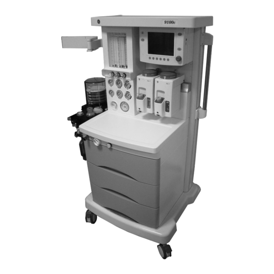
10. ACGO switch (option) 11. ACGO (option) 12. Breathing system 13. Flow controls 14. Mounting arm (option) Figure 1-1 • Front View M1207026 M1207027 MANUAL−DOC, Technical Reference Manual, Technical Reference Manual for 9100c, English Reproduced from the electronic master in MATRIX... - Page 27 3. Equipotential stud 4. Cylinder inlet (option) 5. Pipeline inlet 6. Mains supply inlet 7. System circuit breaker Figure 1-2 • Rear view M1207026 M1207027 MANUAL−DOC, Technical Reference Manual, Technical Reference Manual for 9100c, English Reproduced from the electronic master in MATRIX...
-
Page 28: Symbols Used In The Manual Or On The Equipment
9100c 1.6 Symbols used in the manual or on the equipment Symbols replace words on the equipment, on the display, or in GE Healthcare manuals. No one device or manual uses all the symbols. Warnings and Cautions tell you about dangerous conditions that can occur if you do not follow all instructions in this manual: •... - Page 29 Read to top of float EZchange Canister (CO bypass) Caution: federal law prohibits dispensing without prescription Alarm silence touch key Menu touch key M1207026 M1207027 MANUAL−DOC, Technical Reference Manual, Technical Reference Manual for 9100c, English Reproduced from the electronic master in MATRIX...
- Page 30 This way up Positive pressure of flow sensor Pneumatic Output Negative pressure of flow sensor 1-10 M1207026 M1207027 MANUAL−DOC, Technical Reference Manual, Technical Reference Manual for 9100c, English Reproduced from the electronic master in MATRIX...
-
Page 31: Theory Of Operation
2.4 General Description ......2-14 2.5 9100c Ventilator features ..... . . 2-15 2.5.1 Safety features . - Page 32 2.8.8 Free Breathing Valve ..... 2-27 2.8.9 Breathing Circuit Flow Sensor ....2-27 M1207026 M1207027 MANUAL−DOC, Technical Reference Manual, Technical Reference Manual for 9100c, English Reproduced from the electronic master in MATRIX...
-
Page 33: Theory Overview
The flow of gas through the breathing system. • Electrical signals between the anesthesia machine, including the breathing system, and the ventilator. • Ventilator mechanical subsystems. M1207026 M1207027 MANUAL−DOC, Technical Reference Manual, Technical Reference Manual for 9100c, English Reproduced from the electronic master in MATRIX... -
Page 34: Gas Flow Through The Anesthesia Machine
ON, to the common gas outlet, and into the breathing system. A pressure relief valve limits the maximum outlet pressure. M1207026 M1207027 MANUAL−DOC, Technical Reference Manual, Technical Reference Manual for 9100c, English Reproduced from the electronic master in MATRIX... - Page 35 53. Flow indicator 26. Free breathing check valve 54. To disposal system 27. Atmosphere 55. Active AGSS interface 28. Pop-off valve M1207026 M1207027 MANUAL−DOC, Technical Reference Manual, Technical Reference Manual for 9100c, English Reproduced from the electronic master in MATRIX...
-
Page 36: Physical Connections
2900 2900 1450 2900 1450 1450 N 2 0 ‡ ‡ ‡ ‡ Figure 2-2 • Typical tubing connections - pictorial M1207026 M1207027 MANUAL−DOC, Technical Reference Manual, Technical Reference Manual for 9100c, English Reproduced from the electronic master in MATRIX... -
Page 37: Flow Control
Decreasing the N O flow from the engagement point rotates the O sprocket away on the O knob, increasing the O concentration. M1207026 M1207027 MANUAL−DOC, Technical Reference Manual, Technical Reference Manual for 9100c, English Reproduced from the electronic master in MATRIX... -
Page 38: Flow Through The Breathing System
Scavenged gas paths: APL or pop-off valve. • Flow through the optional EZchange Canister: EZchange ON and EZchange OFF (CO bypass). M1207026 M1207027 MANUAL−DOC, Technical Reference Manual, Technical Reference Manual for 9100c, English Reproduced from the electronic master in MATRIX... -
Page 39: Manual Ventilation
During inspiration, common gas flows from the machine into the inspiratory limb, upstream of the inspiratory check valve. M1207026 M1207027 MANUAL−DOC, Technical Reference Manual, Technical Reference Manual for 9100c, English Reproduced from the electronic master in MATRIX... - Page 40 As circuit pressure approaches the pressure placed on the APL disc, any additional pressure will cause the disc to lift and gas vents to the scavenging system. 2-10 M1207026 M1207027 MANUAL−DOC, Technical Reference Manual, Technical Reference Manual for 9100c, English Reproduced from the electronic master in MATRIX...
-
Page 41: Mechanical Ventilation
(inspiratory check valve) to the patient. During inspiration, common gas flows into the inspiratory limb, upstream of the inspiratory check valve. M1207026 2-11 M1207027 MANUAL−DOC, Technical Reference Manual, Technical Reference Manual for 9100c, English Reproduced from the electronic master in MATRIX... - Page 42 PEEP level. During exhalation, common gas flows backwards through the absorber into the expiratory limb, downstream of the expiratory check valve. 2-12 M1207026 M1207027 MANUAL−DOC, Technical Reference Manual, Technical Reference Manual for 9100c, English Reproduced from the electronic master in MATRIX...
- Page 43 Excess gas vents to the scavenging system through the pop-off valve and the exhalation valve. M1207026 2-13 M1207027 MANUAL−DOC, Technical Reference Manual, Technical Reference Manual for 9100c, English Reproduced from the electronic master in MATRIX...
-
Page 44: General Description
9100c Anesthesia Machine. Figure 2-3 • 9100c Ventilator functional block diagram 2-14 M1207026 M1207027 MANUAL−DOC, Technical Reference Manual, Technical Reference Manual for 9100c, English Reproduced from the electronic master in MATRIX... -
Page 45: 9100C Ventilator Features
Proven mechanical components used. • 10 VA electrical power limiting to potential oxygen enriched environment. • 105 psi burst overpressure protection. M1207026 2-15 M1207027 MANUAL−DOC, Technical Reference Manual, Technical Reference Manual for 9100c, English Reproduced from the electronic master in MATRIX... -
Page 46: 9100C Ventilator Components
9100c 2.6 9100c Ventilator components Major components of the 9100c ventilator are found in different locations of the anesthesia machine. The ventilator package consists of: 1. Display Module – The Display Module includes: • Display Monitor Board • LCD Display •... -
Page 47: Display Module
2. Display Monitor Board (DMB) 3. Speaker 4. LCD display 5. Keyboard front panel 6. Rotary encoder Figure 2-5 • 9100c Display Module M1207026 2-17 M1207027 MANUAL−DOC, Technical Reference Manual, Technical Reference Manual for 9100c, English Reproduced from the electronic master in MATRIX... -
Page 48: Control Sample Board
9100c 2.6.2 Control Sample The Control Sample Board (CSB) is located underneath the tabletop. Board 2-18 M1207026 M1207027 MANUAL−DOC, Technical Reference Manual, Technical Reference Manual for 9100c, English Reproduced from the electronic master in MATRIX... -
Page 49: Pneumatic Vent Engine
PEEP safety valve • Supply pressure sense switch • PEEP control valve • 200 mL reservoir • Calibrated bleed orifice M1207026 2-19 M1207027 MANUAL−DOC, Technical Reference Manual, Technical Reference Manual for 9100c, English Reproduced from the electronic master in MATRIX... -
Page 50: Electronic And Electrical Components
9100c ventilator system. • Input: 90~264 VAC • Output: 15.0 VDC (±2%) at 0–3 A Figure 2-6 • 9100c Ventilator power supply 2-20 M1207026 M1207027 MANUAL−DOC, Technical Reference Manual, Technical Reference Manual for 9100c, English Reproduced from the electronic master in MATRIX... -
Page 51: Sealed Lead Acid Battery
2 Theory of Operation 2.7.3 Sealed Lead A sealed lead acid battery supplies battery backup for the 9100c Acid Battery ventilator. The battery provides: • capacity to operate ventilator system for 30 minutes (fully charged); • the battery is internally fused (auto-resettable). -
Page 52: Control Sample Board
Flow valve control • PEEP valve drive and PEEP safety valve drive Figure 2-7 • Control Sample Board block diagram 2-22 M1207026 M1207027 MANUAL−DOC, Technical Reference Manual, Technical Reference Manual for 9100c, English Reproduced from the electronic master in MATRIX... -
Page 53: Display Monitor Board
Inverter interface • Universal Serial Bus (USB) interface • Alarm audio circuit Figure 2-8 • Display Monitor Board block diagram M1207026 2-23 M1207027 MANUAL−DOC, Technical Reference Manual, Technical Reference Manual for 9100c, English Reproduced from the electronic master in MATRIX... -
Page 54: Ventilator Mechanical Subsystems
8. PEEP safety valve 9. Supply pressure switch Exhalation valve Bellows assembly Breathing circuit flow sensor Figure 2-9 • 9100c Vent Engine 2-24 M1207026 M1207027 MANUAL−DOC, Technical Reference Manual, Technical Reference Manual for 9100c, English Reproduced from the electronic master in MATRIX... -
Page 55: Drive Gas
Pilot control of the exhalation valve is done with PEEP Control Valve (7), Supply Pressure Switch (9), and the PEEP Safety Valve (8). M1207026 2-25 M1207027 MANUAL−DOC, Technical Reference Manual, Technical Reference Manual for 9100c, English Reproduced from the electronic master in MATRIX... -
Page 56: Reservoir And Bleed Resistor
If the pressure in the patient circuit exceeds 4 cm O, the pop-off valve opens to exhaust excess fresh gas flow at a rate up to 4 L/min. 2-26 M1207026 M1207027 MANUAL−DOC, Technical Reference Manual, Technical Reference Manual for 9100c, English Reproduced from the electronic master in MATRIX... -
Page 57: Mechanical Overpressure Valve
The tube closest to the patient connection (13) must be connected to the port labeled “ P+”. Large Small Port Port M1207026 2-27 M1207027 MANUAL−DOC, Technical Reference Manual, Technical Reference Manual for 9100c, English Reproduced from the electronic master in MATRIX... - Page 58 9100c 2-28 M1207026 M1207027 MANUAL−DOC, Technical Reference Manual, Technical Reference Manual for 9100c, English Reproduced from the electronic master in MATRIX...
-
Page 59: Checkout Procedure
3.13 Electrical safety tests ......3-24 M1207026 M1207027 MANUAL−DOC, Technical Reference Manual, Technical Reference Manual for 9100c, English Reproduced from the electronic master in MATRIX... - Page 60 9100c WARNING After any repair or service of the 9100c system, complete all tests in this section. Before you do the tests in this section: • Complete all necessary calibrations and subassembly tests. Refer to the individual procedures for a list of necessary calibrations.
-
Page 61: Ventilator Post-Service Checkout
• Flow Sensor Negative • Flow Sensor Positive Then, complete the checkout procedure for the entire machine in the following sections. M1207026 M1207027 MANUAL−DOC, Technical Reference Manual, Technical Reference Manual for 9100c, English Reproduced from the electronic master in MATRIX... -
Page 62: Inspect The System
• The power cord is connected to a wall outlet. The mains indicator comes on when AC Power is connected. M1207026 M1207027 MANUAL−DOC, Technical Reference Manual, Technical Reference Manual for 9100c, English Reproduced from the electronic master in MATRIX... -
Page 63: Pipeline And Cylinder Tests
6. Connect the pipeline supplies one at a time and ensure that the corresponding gauge indicates pipeline pressure. M1207026 M1207027 MANUAL−DOC, Technical Reference Manual, Technical Reference Manual for 9100c, English Reproduced from the electronic master in MATRIX... -
Page 64: Flow Control Tests
If you overshoot a setting, turn the O flow control clockwise until the N O flow decreases to the previous setting before continuing the test. M1207026 M1207027 MANUAL−DOC, Technical Reference Manual, Technical Reference Manual for 9100c, English Reproduced from the electronic master in MATRIX... -
Page 65: Without O2 Monitoring
2. Connect the pipeline supplies or slowly open the cylinder valves. 3. Turn all flow controls full clockwise (zero flow). 4. If equipped, set the ACGO selector switch to Breathing System. M1207026 M1207027 MANUAL−DOC, Technical Reference Manual, Technical Reference Manual for 9100c, English Reproduced from the electronic master in MATRIX... - Page 66 Set the N O flow (using the The O flow must be greater flow control) to (L/min) than (L/min) M1207026 M1207027 MANUAL−DOC, Technical Reference Manual, Technical Reference Manual for 9100c, English Reproduced from the electronic master in MATRIX...
-
Page 67: Pressure Relief Test
Note: Hold the test adapter to the common gas outlet to avoid loosening. 8. Remove the test device and the adapter. 9. Replace the breathing system. M1207026 M1207027 MANUAL−DOC, Technical Reference Manual, Technical Reference Manual for 9100c, English Reproduced from the electronic master in MATRIX... -
Page 68: O2 Supply Alarm Test
5. Turn all of the flow controls fully clockwise (zero flow). 6. Reconnect the O pipeline supply. 3-10 M1207026 M1207027 MANUAL−DOC, Technical Reference Manual, Technical Reference Manual for 9100c, English Reproduced from the electronic master in MATRIX... -
Page 69: Flush Flow Test
Large leak (if long filling time). Failure • The output of the pressure regulator is incorrect. • The pressure regulator is incorrectly connected. M1207026 3-11 M1207027 MANUAL−DOC, Technical Reference Manual, Technical Reference Manual for 9100c, English Reproduced from the electronic master in MATRIX... -
Page 70: Vaporizer Back Pressure Test
8. Complete steps 5 through 7 for each vaporizer and vaporizer position. 9. Set the system switch to Standby. 10. Turn all of the flow controls fully clockwise (closed). 3-12 M1207026 M1207027 MANUAL−DOC, Technical Reference Manual, Technical Reference Manual for 9100c, English Reproduced from the electronic master in MATRIX... -
Page 71: Low-Pressure Leak Test
(1 L/min for one minute). Turn off all vaporizers at the end of the low-pressure leak test. 6. Flush the system with O M1207026 3-13 M1207027 MANUAL−DOC, Technical Reference Manual, Technical Reference Manual for 9100c, English Reproduced from the electronic master in MATRIX... - Page 72 Set the vaporizer to Off. • Test the remaining vaporizers. 5. Disconnect the test device. 6. Replace the breathing system. 3-14 M1207026 M1207027 MANUAL−DOC, Technical Reference Manual, Technical Reference Manual for 9100c, English Reproduced from the electronic master in MATRIX...
-
Page 73: Positive Low-Pressure Leak Test
4. Keep the flowmeter of the test device vertical for accurate results. 5. Fully open the needle valve on the test device (counterclockwise). M1207026 3-15 M1207027 MANUAL−DOC, Technical Reference Manual, Technical Reference Manual for 9100c, English Reproduced from the electronic master in MATRIX... - Page 74 3. Connect the test adapter port 1 to the common gas outlet. 4. Connect the test device to the test adapter port 2. 3-16 M1207026 M1207027 MANUAL−DOC, Technical Reference Manual, Technical Reference Manual for 9100c, English Reproduced from the electronic master in MATRIX...
- Page 75 Agent mixtures from the low-pressure leak test stay in the WARNING system. Always flush the system with O after the low- pressure leak test (1 L/min for one minute). M1207026 3-17 M1207027 MANUAL−DOC, Technical Reference Manual, Technical Reference Manual for 9100c, English Reproduced from the electronic master in MATRIX...
- Page 76 1 L/min. • Continue the O flow for one minute. • Turn the O flow control fully clockwise (closed). 3-18 M1207026 M1207027 MANUAL−DOC, Technical Reference Manual, Technical Reference Manual for 9100c, English Reproduced from the electronic master in MATRIX...
-
Page 77: Alarm Tests
11. Test the apnea and low airway pressure alarms: • Turn all flow controls fully clockwise. • Set the Bag/Vent switch to Bag. M1207026 3-19 M1207027 MANUAL−DOC, Technical Reference Manual, Technical Reference Manual for 9100c, English Reproduced from the electronic master in MATRIX... - Page 78 100%. • Turn the O flow control fully clockwise (zero flow). 14. Set the system switch to Standby. 3-20 M1207026 M1207027 MANUAL−DOC, Technical Reference Manual, Technical Reference Manual for 9100c, English Reproduced from the electronic master in MATRIX...
-
Page 79: Breathing System Tests
O flush button to approximately 30 cm H • Release the O flush button. The pressure must not M1207026 3-21 M1207027 MANUAL−DOC, Technical Reference Manual, Technical Reference Manual for 9100c, English Reproduced from the electronic master in MATRIX... - Page 80 10. Set the system switch to Standby. Make sure that there are no test plugs or other objects WARNING caught in the breathing system. 3-22 M1207026 M1207027 MANUAL−DOC, Technical Reference Manual, Technical Reference Manual for 9100c, English Reproduced from the electronic master in MATRIX...
-
Page 81: Power Failure Test
5. Make sure the following message is on the ventilator display: • “On Battery - Power OK?” 6. Connect the power cord again. 7. Make sure the alarm cancels. M1207026 3-23 M1207027 MANUAL−DOC, Technical Reference Manual, Technical Reference Manual for 9100c, English Reproduced from the electronic master in MATRIX... -
Page 82: Electrical Safety Tests
2. Make sure that the resistance to ground is less than 0.2 between an exposed metal surface and the ground pin on the power cord. 3-24 M1207026 M1207027 MANUAL−DOC, Technical Reference Manual, Technical Reference Manual for 9100c, English Reproduced from the electronic master in MATRIX... -
Page 83: Service Tests And Service Mode
4.5 Calibration ........4-13 M1207026 M1207027 MANUAL−DOC, Technical Reference Manual, Technical Reference Manual for 9100c, English Reproduced from the electronic master in MATRIX... - Page 84 4.6.4 Altitude Setting ......4-29 M1207026 M1207027 MANUAL−DOC, Technical Reference Manual, Technical Reference Manual for 9100c, English Reproduced from the electronic master in MATRIX...
-
Page 85: Self Tests
CSB and alarm MCU communication If one or more of these tests fail, the display provides a readout of the problem. M1207026 M1207027 MANUAL−DOC, Technical Reference Manual, Technical Reference Manual for 9100c, English Reproduced from the electronic master in MATRIX... -
Page 86: Service Mode
The following sections in this manual are sequenced in the order that they appear on the screen. M1207026 M1207027 MANUAL−DOC, Technical Reference Manual, Technical Reference Manual for 9100c, English Reproduced from the electronic master in MATRIX... -
Page 87: Ventilator Information
The Software Version includes: • CSB Version • DMB Version • Alarm Version The “System Time” displays the time set in the ventilator screen. M1207026 M1207027 MANUAL−DOC, Technical Reference Manual, Technical Reference Manual for 9100c, English Reproduced from the electronic master in MATRIX... -
Page 88: Diagnostic Test/Tools
4.4 Diagnostic Test/Tools The Diagnostic Tests/Tools menu includes a selection of items that look at individual subsystems of the 9100c Ventilator. M1207026 M1207027 MANUAL−DOC, Technical Reference Manual, Technical Reference Manual for 9100c, English Reproduced from the electronic master in MATRIX... -
Page 89: Discrete I/O Signal
— On or Off Electronic switches • Sensor Status — Connected or Disconnected • Breathing Circuit — Connected or Disconnected M1207026 M1207027 MANUAL−DOC, Technical Reference Manual, Technical Reference Manual for 9100c, English Reproduced from the electronic master in MATRIX... -
Page 90: Display Battery Status
Battery Status “Battery Charging” — Battery is charging. “Battery is ON - Power is OK??” — System is running on battery. M1207026 M1207027 MANUAL−DOC, Technical Reference Manual, Technical Reference Manual for 9100c, English Reproduced from the electronic master in MATRIX... -
Page 91: Test Keypad
If any of the select buttons test fails, replace the front panel keyboard assembly. If the encoder knob test fails, replace the rotary encoder assembly. M1207026 M1207027 MANUAL−DOC, Technical Reference Manual, Technical Reference Manual for 9100c, English Reproduced from the electronic master in MATRIX... -
Page 92: Self - Test
When the result is “Fail”, the icon background should be red. Remarks If one or more of these tests fail, please check the CSB, DMB, Vent Engine and the harnesses. 4-10 M1207026 M1207027 MANUAL−DOC, Technical Reference Manual, Technical Reference Manual for 9100c, English Reproduced from the electronic master in MATRIX... -
Page 93: Valve - Test Tool
When setting the Inspiratory Valve or the PEEP Valve: • Turn the encoder clockwise to increase the values. • Turn the encoder counterclockwise to decrease the values. M1207026 4-11 M1207027 MANUAL−DOC, Technical Reference Manual, Technical Reference Manual for 9100c, English Reproduced from the electronic master in MATRIX... -
Page 94: Breathing System Leak Test
The leak rate is the fresh gas flow needed to maintain 30 cm • The system should have a leak rate < 200 mL/min. 4-12 M1207026 M1207027 MANUAL−DOC, Technical Reference Manual, Technical Reference Manual for 9100c, English Reproduced from the electronic master in MATRIX... -
Page 95: Calibration
These procedures require you to disassemble and reassemble parts of the breathing system. Accordingly, the procedures are arranged to minimize the disassembly and reassembly process. M1207026 4-13 M1207027 MANUAL−DOC, Technical Reference Manual, Technical Reference Manual for 9100c, English Reproduced from the electronic master in MATRIX... -
Page 96: Paw Zero
Remarks Ensure that the breathing system is removed. “Fail” indicates a problem in the CSB (Airway pressure transducer) 4-14 M1207026 M1207027 MANUAL−DOC, Technical Reference Manual, Technical Reference Manual for 9100c, English Reproduced from the electronic master in MATRIX... -
Page 97: Paw Gain
9. Set the fresh gas flow to zero upon the completion of calibration Remarks “Fail” indicates a problem in the CSB (Airway pressure transducer). M1207026 4-15 M1207027 MANUAL−DOC, Technical Reference Manual, Technical Reference Manual for 9100c, English Reproduced from the electronic master in MATRIX... -
Page 98: O2 Cell
Place the sensor that passed the 21% test in the breathing system and expose it to 100% O “Fail” incidents a problem in the O Cell. Replace if necessary. 4-16 M1207026 M1207027 MANUAL−DOC, Technical Reference Manual, Technical Reference Manual for 9100c, English Reproduced from the electronic master in MATRIX... -
Page 99: Peep Valve
8. Connect the pediatric bag(1L) (F) to the calibration pipe using elbow fitting (G). Ensure that the test tubing is leak free. M1207026 4-17 M1207027 MANUAL−DOC, Technical Reference Manual, Technical Reference Manual for 9100c, English Reproduced from the electronic master in MATRIX... - Page 100 The data is stored in EEPROM and is used during normal operation to compensate for the individual valve’s output characteristics. 4-18 M1207026 M1207027 MANUAL−DOC, Technical Reference Manual, Technical Reference Manual for 9100c, English Reproduced from the electronic master in MATRIX...
-
Page 101: Flow Zero
“ P+” and “ P-”. If the calibration procedure fails, it indicates a problem in the flow measurement differential pressure transducers of the CSB. M1207026 4-19 M1207027 MANUAL−DOC, Technical Reference Manual, Technical Reference Manual for 9100c, English Reproduced from the electronic master in MATRIX... -
Page 102: Inspiratory Flow Valve
6. Connect the tubing from calibration pipe to the calibration fitting. Ensure that the test tubing is leak free and the flow sensor tubes are connected. 4-20 M1207026 M1207027 MANUAL−DOC, Technical Reference Manual, Technical Reference Manual for 9100c, English Reproduced from the electronic master in MATRIX... - Page 103 The data is stored in EEPROM and is used during normal operation to compensate for the individual valve’s output characteristics. M1207026 4-21 M1207027 MANUAL−DOC, Technical Reference Manual, Technical Reference Manual for 9100c, English Reproduced from the electronic master in MATRIX...
-
Page 104: Flow Sensor Positive
5. Connect the calibration fitting (E) to the inspiratory flow port. 6. Connect the tubing from calibration pipe to the calibration fitting. Ensure that the test tubing is leak free. 4-22 M1207026 M1207027 MANUAL−DOC, Technical Reference Manual, Technical Reference Manual for 9100c, English Reproduced from the electronic master in MATRIX... - Page 105 The data is stored in EEPROM and is used during normal operation to compensate for the individual flow sensor output characteristics. M1207026 4-23 M1207027 MANUAL−DOC, Technical Reference Manual, Technical Reference Manual for 9100c, English Reproduced from the electronic master in MATRIX...
-
Page 106: Flow Sensor Negative
The data is stored in EEPROM and is used during normal operation to compensate for the individual flow sensor output characteristics. 4-24 M1207026 M1207027 MANUAL−DOC, Technical Reference Manual, Technical Reference Manual for 9100c, English Reproduced from the electronic master in MATRIX... -
Page 107: Calibration Coefficient
The data is stored in EEPROM and is used during the calibration to compensate for the individual calibration orifice characteristics. M1207026 4-25 M1207027 MANUAL−DOC, Technical Reference Manual, Technical Reference Manual for 9100c, English Reproduced from the electronic master in MATRIX... -
Page 108: Configuration/Upgrade
If the ventilator “Key Code” is changed, the new code should be recorded on the display module side panel label. 4-26 M1207026 M1207027 MANUAL−DOC, Technical Reference Manual, Technical Reference Manual for 9100c, English Reproduced from the electronic master in MATRIX... -
Page 109: Software Upgrade
Remarks Ensure the AC power is ON during the upgrade. M1207026 4-27 M1207027 MANUAL−DOC, Technical Reference Manual, Technical Reference Manual for 9100c, English Reproduced from the electronic master in MATRIX... -
Page 110: Language
Korean • French • Spanish • Portuguese The language setting is stored in EEPROM with the default setting as English. 4-28 M1207026 M1207027 MANUAL−DOC, Technical Reference Manual, Technical Reference Manual for 9100c, English Reproduced from the electronic master in MATRIX... -
Page 111: Altitude Setting
Altitude settings range from -400 to 3600 meters in increments of 100 meters. Remarks The setting is saved in EEPROM; the default value is 0 meter. M1207026 4-29 M1207027 MANUAL−DOC, Technical Reference Manual, Technical Reference Manual for 9100c, English Reproduced from the electronic master in MATRIX... - Page 112 9100c 4-30 M1207026 M1207027 MANUAL−DOC, Technical Reference Manual, Technical Reference Manual for 9100c, English Reproduced from the electronic master in MATRIX...
-
Page 113: Calibration
5.4.1 Zero the pressure gauge ....5-8 5.4.2 Checking the pressure gauge accuracy ..5-9 M1207026 M1207027 MANUAL−DOC, Technical Reference Manual, Technical Reference Manual for 9100c, English Reproduced from the electronic master in MATRIX... -
Page 114: Cylinder Regulators
5. Remove the plug from the test port and connect a test device capable of measuring 689 kPa (100 psi). Remove Plug M1207026 M1207027 MANUAL−DOC, Technical Reference Manual, Technical Reference Manual for 9100c, English Reproduced from the electronic master in MATRIX... -
Page 115: Test Cylinder Regulators
7 kPa (1 psi). This adjusts the “low flow” regulated output to the high side of the specification so that the M1207026 M1207027 MANUAL−DOC, Technical Reference Manual, Technical Reference Manual for 9100c, English Reproduced from the electronic master in MATRIX... - Page 116 7 kPa (1 psi). This adjusts the “low flow” regulated output to M1207026 M1207027 MANUAL−DOC, Technical Reference Manual, Technical Reference Manual for 9100c, English Reproduced from the electronic master in MATRIX...
-
Page 117: Adjusting Cylinder Regulators
11. Replace the large rear upper panel. 12. Perform the checkout procedure (Section 3). 5.1.3 Adjusting Important: Cylinder supplies in a 9100c machine must have all high- Cylinder Regulators pressure regulators set to the same pressure range. If a regulator is replaced, the replacement regulator must be set (as required) to the same specification as the one removed. -
Page 118: Low-Pressure Regulators
8. Disconnect the pressure meter and reconnect the tubings. 9. After all regulators have been tested, perform the Post-service checkout (Section 3). M1207026 M1207027 MANUAL−DOC, Technical Reference Manual, Technical Reference Manual for 9100c, English Reproduced from the electronic master in MATRIX... -
Page 119: Hypoxic Guard
The hypoxic guard is an internal system that is not serviceable. If the hypoxic guard is out of calibration or is malfunctioning, replace the entire flow control assembly. M1207026 M1207027 MANUAL−DOC, Technical Reference Manual, Technical Reference Manual for 9100c, English Reproduced from the electronic master in MATRIX... -
Page 120: Airway Pressure Gauge
9. If required, repeat zero and span procedure (Section 5.4.1 and 5.4.2). 10. Replace the lens cover. Zero Adjust M1207026 M1207027 MANUAL−DOC, Technical Reference Manual, Technical Reference Manual for 9100c, English Reproduced from the electronic master in MATRIX... -
Page 121: Checking The Pressure Gauge Accuracy
0±1 cm H 40 cm H 40±2 cm H -5 cm H -5±2 cm H Pressure Gauge Fitting Test Device Low-pressure Source (Syringe) M1207026 M1207027 MANUAL−DOC, Technical Reference Manual, Technical Reference Manual for 9100c, English Reproduced from the electronic master in MATRIX... - Page 122 9100c 5-10 M1207026 M1207027 MANUAL−DOC, Technical Reference Manual, Technical Reference Manual for 9100c, English Reproduced from the electronic master in MATRIX...
-
Page 123: Installation And Maintenance
In this section 6.1 9100c Installation Checklist ..... . 6-2 6.2 9100c Planned Maintenance ..... 6-4 6.2.1 Every twelve (12) months . -
Page 124: 9100C Installation Checklist
Pipeline and cylinder tests (Section 3.3). c. Flow control test (Section 3.4). d. Pressure relief tests (Section 3.5). e. O supply alarm test (Section 3.6). M1207026 M1207027 MANUAL−DOC, Technical Reference Manual, Technical Reference Manual for 9100c, English Reproduced from the electronic master in MATRIX... - Page 125 Low-pressure leak test (Section 3.9). Alarm tests (Section 3.10). Breathing system tests (Section 3.11). k. Power failure test (Section 3.12). Electrical safety tests (Section 3.13). M1207026 M1207027 MANUAL−DOC, Technical Reference Manual, Technical Reference Manual for 9100c, English Reproduced from the electronic master in MATRIX...
-
Page 126: 9100C Planned Maintenance
Flow Sensor Positive (Section 4.5.7) • • Flow Sensor Negative (Section 4.5.8) 4. Inspect the system (Section 3.2) 5. Pipeline and cylinder tests (Section 3.3) M1207026 M1207027 MANUAL−DOC, Technical Reference Manual, Technical Reference Manual for 9100c, English Reproduced from the electronic master in MATRIX... -
Page 127: Every Twenty-Four (24) Months
1. Replace the free breathing flapper valve. 2. Replace the free breathing valve o-ring. M1207026 M1207027 MANUAL−DOC, Technical Reference Manual, Technical Reference Manual for 9100c, English Reproduced from the electronic master in MATRIX... -
Page 128: Free Breathing Valve Maintenance
6. Scissor the tail, ensure the tail is not longer than 3 mm. 7. Reassemble the system. 8. Perform the Preoperative Checkout Procedure. (refer to the 9100c User’s Reference manual). M1207026 M1207027 MANUAL−DOC, Technical Reference Manual, Technical Reference Manual for 9100c, English Reproduced from the electronic master in MATRIX... -
Page 129: Adjust Drive Gas Regulator
You can verify this pressure by attaching a pressure test device to the regulator pressure port (shown below) and adjusting the regulator to 172 ±1.72 kPa (25 ±0.25 psi). M1207026 M1207027 MANUAL−DOC, Technical Reference Manual, Technical Reference Manual for 9100c, English Reproduced from the electronic master in MATRIX... -
Page 130: Mopv Pressure Relief Valve Test
5. Remove the test adapter from the common gas outlet. 6. Reassemble the system. 7. Perform the Preoperative Checkout Procedure (refer to the 9100c User’s Reference Manual). M1207026 M1207027 MANUAL−DOC, Technical Reference Manual, Technical Reference Manual for 9100c, English Reproduced from the electronic master in MATRIX... -
Page 131: Exhalation Valve Relief Valve Test
Remove the patient Y-piece from the bag port handle. 10. Reassemble in reverse order. 11. Perform the Preoperative Checkout Procedure (refer to the 9100c User’s Reference Manual). M1207026 M1207027 MANUAL−DOC, Technical Reference Manual, Technical Reference Manual for 9100c, English Reproduced from the electronic master in MATRIX... - Page 132 9100c 6-10 M1207026 M1207027 MANUAL−DOC, Technical Reference Manual, Technical Reference Manual for 9100c, English Reproduced from the electronic master in MATRIX...
-
Page 133: Troubleshooting
7.4 Alarm and Shutdown messages ....7-8 M1207026 M1207027 MANUAL−DOC, Technical Reference Manual, Technical Reference Manual for 9100c, English Reproduced from the electronic master in MATRIX... -
Page 134: General Troubleshooting
Inspect the bellows for damage; replace. M1207026 M1207027 MANUAL−DOC, Technical Reference Manual, Technical Reference Manual for 9100c, English Reproduced from the electronic master in MATRIX... - Page 135 O flow Unable to begin mechanical No O supply Check O supply. ventilation Defective Manual/Mechanical Check Manual/Mechanical ventilation switch. ventilation switch M1207026 M1207027 MANUAL−DOC, Technical Reference Manual, Technical Reference Manual for 9100c, English Reproduced from the electronic master in MATRIX...
-
Page 136: Breathing System Leak Test Guide
Do not use a test plug that is small enough to fall into the breathing system. • Make sure that there are no test plugs or other objects caught in the breathing system. M1207026 M1207027 MANUAL−DOC, Technical Reference Manual, Technical Reference Manual for 9100c, English Reproduced from the electronic master in MATRIX... -
Page 137: Breathing System Leak Test
The pressure must not decrease. A pressure decrease large enough to see on the gauge indicates an unacceptable leak. M1207026 M1207027 MANUAL−DOC, Technical Reference Manual, Technical Reference Manual for 9100c, English Reproduced from the electronic master in MATRIX... - Page 138 10. Set the system switch to Standby. Make sure that there are no test plugs or other objects WARNING caught in the breathing system. M1207026 M1207027 MANUAL−DOC, Technical Reference Manual, Technical Reference Manual for 9100c, English Reproduced from the electronic master in MATRIX...
-
Page 139: Troubleshooting Guide
Power for the speaker comes from the Power Section of the DMB. Drive for the speaker comes from the Digital Section of the DMB board. M1207026 M1207027 MANUAL−DOC, Technical Reference Manual, Technical Reference Manual for 9100c, English Reproduced from the electronic master in MATRIX... -
Page 140: Alarm And Shutdown Messages
0.5 seconds. to save power. Is the mains indicator light on? Make sure power is connected and circuit breakers are closed. M1207026 M1207027 MANUAL−DOC, Technical Reference Manual, Technical Reference Manual for 9100c, English Reproduced from the electronic master in MATRIX... - Page 141 Does the sensor see 21% O in room air? Calibrate O sensor. Replace O sensor. As sensors wear out, the measured% O decreases. M1207026 M1207027 MANUAL−DOC, Technical Reference Manual, Technical Reference Manual for 9100c, English Reproduced from the electronic master in MATRIX...
- Page 142 This Check tubing connections. alarm is suspended for 9 Check alarm settings. breaths after you change the ventilator settings. 7-10 M1207026 M1207027 MANUAL−DOC, Technical Reference Manual, Technical Reference Manual for 9100c, English Reproduced from the electronic master in MATRIX...
-
Page 143: Software Installation
8.4 Software Installation ......8-6 M1207026 M1207027 MANUAL−DOC, Technical Reference Manual, Technical Reference Manual for 9100c, English Reproduced from the electronic master in MATRIX... -
Page 144: Before Replacing The Display Monitor Board
When new Display Monitor Board is installed, the Function Upgrade options are reset to “not installed” (Section 4.6.1). To help ensure that, after repair or software replacement, the 9100c system will include all features that are currently installed and enabled, record the current Function Upgrade options installed. -
Page 145: Key/Bid Label (Key Code)
The Control Board here only refer to the replacement Display Monitor Note Board for the 9100c system. The replacement Control Sample Board doesn’t need the appropriate optional features Key Code. 2. Access the Key Code Generator on the following web site. -
Page 146: After Replacing The Dmb (Display Module)
Board kit (or on the Display Module) and the Key Code sticker to the left side panel of the Display Module. M1207026 M1207027 MANUAL−DOC, Technical Reference Manual, Technical Reference Manual for 9100c, English Reproduced from the electronic master in MATRIX... -
Page 147: After Replacing The Csb
Load the appropriate software revision (Section 8.4) using software USB disk that matches the software revision of the replaced Control Sample Board (CSB). M1207026 M1207027 MANUAL−DOC, Technical Reference Manual, Technical Reference Manual for 9100c, English Reproduced from the electronic master in MATRIX... -
Page 148: Software Installation
8. On the Altitude Setting menu of the Service Mode, reset the Altitude (Section 4.6.4). 9. Perform the preoperative checkout procedure. M1207026 M1207027 MANUAL−DOC, Technical Reference Manual, Technical Reference Manual for 9100c, English Reproduced from the electronic master in MATRIX... -
Page 149: Repair Procedure
9.8 Replace O2 supply switch ..... . 9-15 M1207026 M1207027 MANUAL−DOC, Technical Reference Manual, Technical Reference Manual for 9100c, English Reproduced from the electronic master in MATRIX... - Page 150 9.17.1 To remove the Vent Engine ....9-39 9.17.2 Replacing Vent Engine components ..9-40 M1207026 M1207027 MANUAL−DOC, Technical Reference Manual, Technical Reference Manual for 9100c, English Reproduced from the electronic master in MATRIX...
- Page 151 After repairs are completed, always perform the checkout procedure before returning the system to clinical use. Refer to Section 3 of this manual. M1207026 M1207027 MANUAL−DOC, Technical Reference Manual, Technical Reference Manual for 9100c, English Reproduced from the electronic master in MATRIX...
-
Page 152: How To Bleed Gas Pressure From The Machine
(or close the O cylinder valve). • Push the O flush button to bleed O from the system. M1207026 M1207027 MANUAL−DOC, Technical Reference Manual, Technical Reference Manual for 9100c, English Reproduced from the electronic master in MATRIX... -
Page 153: How To Remove The Rear Panels
5. Remove the small upper rear panel (B) to access the access the electrical enclosure. M1207026 M1207027 MANUAL−DOC, Technical Reference Manual, Technical Reference Manual for 9100c, English Reproduced from the electronic master in MATRIX... -
Page 154: To Remove The Lower Access Panel
3. If present, remove the inboard cylinders. 4. To remove the lower access panel, fully loosen the six screws that hold the panel in place. M1207026 M1207027 MANUAL−DOC, Technical Reference Manual, Technical Reference Manual for 9100c, English Reproduced from the electronic master in MATRIX... -
Page 155: How To Remove The Tabletop
(access from below the rim of the tabletop). To remove the tabletop: 1. Loosen the two screws (A). 2. Slide the tabletop forward and lift to remove. M1207026 M1207027 MANUAL−DOC, Technical Reference Manual, Technical Reference Manual for 9100c, English Reproduced from the electronic master in MATRIX... -
Page 156: How To Remove The Upper Shelf
To remove the upper shelf: 1. Loosen the ten screws (A). 2. Lift the upper shelf. M1207026 M1207027 MANUAL−DOC, Technical Reference Manual, Technical Reference Manual for 9100c, English Reproduced from the electronic master in MATRIX... -
Page 157: Service The Pipeline Inlet Manifold Components
Note: Make sure to push the new check valve all the way back into the opening until it bottoms out on the shoulder. 6. Install the pipeline inlet fitting. M1207026 M1207027 MANUAL−DOC, Technical Reference Manual, Technical Reference Manual for 9100c, English Reproduced from the electronic master in MATRIX... -
Page 158: Replace The Inlet Manifold
(5) 5. To reassemble, perform the previous steps in reverse order. 6. Perform the checkout procedure (Section 3). 9-10 M1207026 M1207027 MANUAL−DOC, Technical Reference Manual, Technical Reference Manual for 9100c, English Reproduced from the electronic master in MATRIX... -
Page 159: Service The Cylinder Supply Modules
Note: A brass retaining ring keeps the filter inside the inlet adapter. 3. Thread a 6-mm screw (two turns only) into the brass retaining ring and pull it out. M1207026 9-11 M1207027 MANUAL−DOC, Technical Reference Manual, Technical Reference Manual for 9100c, English Reproduced from the electronic master in MATRIX... -
Page 160: Replace Cylinder Check Valve
The cylinder check valve is not a replaceable item. If the check valve cylinder check valve is defective, you must replace the complete cylinder supply module. 9-12 M1207026 M1207027 MANUAL−DOC, Technical Reference Manual, Technical Reference Manual for 9100c, English Reproduced from the electronic master in MATRIX... -
Page 161: Replace System Switch Assembly
Install the switch assembly through the gauge panel. • Push the knob collar in with the indicator up and turn it clockwise until it locks. M1207026 9-13 M1207027 MANUAL−DOC, Technical Reference Manual, Technical Reference Manual for 9100c, English Reproduced from the electronic master in MATRIX... - Page 162 • Make sure that the display turns Off. 11. Reinstall the rear panel. 12. Perform the checkout procedure (Section 3). 9-14 M1207026 M1207027 MANUAL−DOC, Technical Reference Manual, Technical Reference Manual for 9100c, English Reproduced from the electronic master in MATRIX...
-
Page 163: Replace O2 Supply Switch
10. Disconnect the gauge and plug the test port. 11. To reassemble, perform the previous steps in reverse order. 12. Perform the checkout procedure (Section 3). M1207026 9-15 M1207027 MANUAL−DOC, Technical Reference Manual, Technical Reference Manual for 9100c, English Reproduced from the electronic master in MATRIX... -
Page 164: Replace The Flowmeter Module
Note: Two screws from each side panel. Mounting Screw 8. To reinstall, perform the previous steps in reverse order. 9. Perform the checkout procedure (Section 3). 9-16 M1207026 M1207027 MANUAL−DOC, Technical Reference Manual, Technical Reference Manual for 9100c, English Reproduced from the electronic master in MATRIX... -
Page 165: Service Vaporizer Manifold Parts
8. To reassemble, perform the previous steps in reverse order. 9. Complete the port valve checkout procedure described below (Section 9.10.2). M1207026 9-17 M1207027 MANUAL−DOC, Technical Reference Manual, Technical Reference Manual for 9100c, English Reproduced from the electronic master in MATRIX... -
Page 166: Checkout Procedure For Manifold Port Valve
WARNING If the valve test tool is not removed before flowing gas through the system, pneumatic head damage could result. 9-18 M1207026 M1207027 MANUAL−DOC, Technical Reference Manual, Technical Reference Manual for 9100c, English Reproduced from the electronic master in MATRIX... -
Page 167: Replace Vaporizer Manifold Check Valve
The valve body, o-ring, and flapper do not come out with the block. They stay intact at the back of the vaporizer manifold. M1207026 9-19 M1207027 MANUAL−DOC, Technical Reference Manual, Technical Reference Manual for 9100c, English Reproduced from the electronic master in MATRIX... - Page 168 16. Install the vaporizer front panel. 17. Perform the checkout procedure (Section 3). 9-20 M1207026 M1207027 MANUAL−DOC, Technical Reference Manual, Technical Reference Manual for 9100c, English Reproduced from the electronic master in MATRIX...
-
Page 169: Replace Vaporizer Pressure Relief Valve
7. Reassemble the machine in reverse order. 8. Perform the checkout procedure (Section 3). M1207026 9-21 M1207027 MANUAL−DOC, Technical Reference Manual, Technical Reference Manual for 9100c, English Reproduced from the electronic master in MATRIX... -
Page 170: Service Acgo Switch
9. Remove the knob assembly and protective shroud from the machine. 10. Remove the valve from the silicone output tubes. 9-22 M1207026 M1207027 MANUAL−DOC, Technical Reference Manual, Technical Reference Manual for 9100c, English Reproduced from the electronic master in MATRIX... - Page 171 13. Reconnect the wires to the flush pressure switch at the top of the valve(upper and lower terminals). 14. Replace the tabletop. M1207026 9-23 M1207027 MANUAL−DOC, Technical Reference Manual, Technical Reference Manual for 9100c, English Reproduced from the electronic master in MATRIX...
-
Page 172: Clean Or Replace Acgo Port Flapper Valve
6. Lubricate the o-ring sparingly with Krytox (do not get Krytox on the flapper). 7. Insert the flapper assembly into the ACGO outlet with the flapper 8. Replace the cap. 9-24 M1207026 M1207027 MANUAL−DOC, Technical Reference Manual, Technical Reference Manual for 9100c, English Reproduced from the electronic master in MATRIX... -
Page 173: Replace The Breathing System Components
5. Reassemble in reverse order. 6. Reinstall the breathing system. 7. Perform the checkout procedure (Section 3). M1207026 9-25 M1207027 MANUAL−DOC, Technical Reference Manual, Technical Reference Manual for 9100c, English Reproduced from the electronic master in MATRIX... -
Page 174: Replace Bag/Vent Switch Assembly
O-rings 5. Replace the Bag/Vent in reverse order. 6. Reinstall the breathing system. 7. Perform the checkout procedure (Section 3). 9-26 M1207026 M1207027 MANUAL−DOC, Technical Reference Manual, Technical Reference Manual for 9100c, English Reproduced from the electronic master in MATRIX... -
Page 175: Replace The Bag Port
5. Replace the bag port in reverse order. 6. Reinstall the breathing system. 7. Perform the checkout procedure (Section 3). M1207026 9-27 M1207027 MANUAL−DOC, Technical Reference Manual, Technical Reference Manual for 9100c, English Reproduced from the electronic master in MATRIX... -
Page 176: Replace The Disc Seat Of Inspiratory/Expiratory Check Valves
• The inspiratory check valve rises during inspiration and falls at the start of expiration. Perform the post-service checkout procedure. 9-28 M1207026 M1207027 MANUAL−DOC, Technical Reference Manual, Technical Reference Manual for 9100c, English Reproduced from the electronic master in MATRIX... -
Page 177: Ezchange Canister Spring Replacement
8. Install the module cover. 9. Install the EZchange module. 10. Verify that the ‘No CO2 absorption’ message appears on the screen when the absorber canister is released. 11. Perform the Preoperative Checkout Procedure (refer to the 9100c User’s Reference manual). M1207026 9-29 M1207027 MANUAL−DOC, Technical Reference Manual, Technical Reference Manual for 9100c, English... -
Page 178: Replace Casters
2. Remove the absorber, the vaporizers, gas cylinders, drawers and all auxiliary equipment. To prevent damage, do not tip the 9100c machine more CAUTION than 10 degrees from vertical. 3. Block the opposite wheels; then, block up the machine until there is enough room to remove the defective caster. -
Page 179: Replace Task Light Switch
3. Remove the switch from the top shelf using the small needle- nose pliers. 4. To replace the switch, reassemble in reverse order. Connectors Switch M1207026 9-31 M1207027 MANUAL−DOC, Technical Reference Manual, Technical Reference Manual for 9100c, English Reproduced from the electronic master in MATRIX... -
Page 180: Replace Display And Cable
• the rear upper panel (Section 9.2), • the AC inlet access panel (Section 9.2), • the tabletop (Section 9.3). 9-32 M1207026 M1207027 MANUAL−DOC, Technical Reference Manual, Technical Reference Manual for 9100c, English Reproduced from the electronic master in MATRIX... -
Page 181: Service The Display Module
2. Loosen the screws (C) that hold the two enclosures together (one in each corner). 3. Carefully separate the rear enclosure (A) from the front enclosure (B). M1207026 9-33 M1207027 MANUAL−DOC, Technical Reference Manual, Technical Reference Manual for 9100c, English Reproduced from the electronic master in MATRIX... -
Page 182: Display Monitor Board
The flex cable (B) for the LCD display inserts into a ZIF (zero Note insertion force) connector on the DMB. 9-34 M1207026 M1207027 MANUAL−DOC, Technical Reference Manual, Technical Reference Manual for 9100c, English Reproduced from the electronic master in MATRIX... - Page 183 Carefully insert the cable until all the “fingers” are below the surface of the shell. Push the shell to the locked position. M1207026 9-35 M1207027 MANUAL−DOC, Technical Reference Manual, Technical Reference Manual for 9100c, English Reproduced from the electronic master in MATRIX...
-
Page 184: Front Enclosure With Dmb Removed
2. Remove the nut and washer that hold the encoder to the keyboard. 3. Replace the encoder switch in reverse order (note the orientation of the attached ribbon cable). 9-36 M1207026 M1207027 MANUAL−DOC, Technical Reference Manual, Technical Reference Manual for 9100c, English Reproduced from the electronic master in MATRIX... - Page 185 LCD display to the mounting bracket. 2. If required, clean the enclosure window (if new, remove the protective film). 3. Reassembly in reverse order. M1207026 9-37 M1207027 MANUAL−DOC, Technical Reference Manual, Technical Reference Manual for 9100c, English Reproduced from the electronic master in MATRIX...
-
Page 186: Service The Vent Engine
Inlet Filter - located under the gas inlet valve (7) • Flow Control Valve (8) • Drive Gas Regulator (9) 9-38 M1207026 M1207027 MANUAL−DOC, Technical Reference Manual, Technical Reference Manual for 9100c, English Reproduced from the electronic master in MATRIX... -
Page 187: To Remove The Vent Engine
6. Loosen the four screws to remove the Vent Engine. 7. To replace the Vent Engine, reassemble in reverse order. M1207026 9-39 M1207027 MANUAL−DOC, Technical Reference Manual, Technical Reference Manual for 9100c, English Reproduced from the electronic master in MATRIX... -
Page 188: Replacing Vent Engine Components
Note orientation of the flow valve. Also inspect the two o-rings that seal it to the manifold. Replace as necessary. 9-40 M1207026 M1207027 MANUAL−DOC, Technical Reference Manual, Technical Reference Manual for 9100c, English Reproduced from the electronic master in MATRIX... -
Page 189: Illustrated Parts
10.14 Breathing System ......10-19 10.14.1 Breathing system - front view ... . 10-19 M1207026 10-1 M1207027 MANUAL−DOC, Technical Reference Manual, Technical Reference Manual for 9100c, English Reproduced from the electronic master in MATRIX... - Page 190 10.20.3 Active AGSS ......10-40 10.21 CGO Valve, AGSS Installation, AGSS Flowtube . . 10-42 10-2 M1207026 M1207027 MANUAL−DOC, Technical Reference Manual, Technical Reference Manual for 9100c, English Reproduced from the electronic master in MATRIX...
-
Page 191: Service Tools
Refer to section 5.1 Low-pressure test device (digital manometer or test Refer to section 5.4.2 gauge) with an accuracy of ±2% of reading M1207026 10-3 M1207027 MANUAL−DOC, Technical Reference Manual, Technical Reference Manual for 9100c, English Reproduced from the electronic master in MATRIX... -
Page 192: Test Tools
Not Shown Plug, stopper Refer to Section 6.6 M1210946 Tool to help disconnect tubing from Legris fittings 2900-0000-000 Test lung 0219-7210-300 10-4 M1207026 M1207027 MANUAL−DOC, Technical Reference Manual, Technical Reference Manual for 9100c, English Reproduced from the electronic master in MATRIX... -
Page 193: External Components - Front View
Screw, ST4.2x13, GB/T845-1985, Fe/Ep Ni M1168734-S Slide, drawer 1009-3084-000 Screw, M4x8 Nyloc 1009-3183-000 Sticker, shelf top M1162712-S (10) Screw with washer, M4x10 M1168760-S (10) M1207026 10-5 M1207027 MANUAL−DOC, Technical Reference Manual, Technical Reference Manual for 9100c, English Reproduced from the electronic master in MATRIX... -
Page 194: External Components - Front View References
Refer to section 10.14 “Display Module” Refer to section 10.16 “Vaporizer manifold” Refer to section 10.10 “Tabletop pan components” Refer to section 10.12 10-6 M1207026 M1207027 MANUAL−DOC, Technical Reference Manual, Technical Reference Manual for 9100c, English Reproduced from the electronic master in MATRIX... -
Page 195: External Components - Rear View
Refer to section 10.9 “Rear panel components” Refer to section 10.6 “Anesthetic Gas Scavenging System - AGSS” Refer to section 10.21 M1207026 10-7 M1207027 MANUAL−DOC, Technical Reference Manual, Technical Reference Manual for 9100c, English Reproduced from the electronic master in MATRIX... -
Page 196: Front Panel, Gauges And System Switch
Tubing, OD.125IN HPO Wall. 032IN LG 450mm CP 1006-3716-000 Plate, gauge blanking 1009-3045-000 Plate, gauge blank backing 1009-3147-000 Palnut 1009-3090-000 10-8 M1207026 M1207027 MANUAL−DOC, Technical Reference Manual, Technical Reference Manual for 9100c, English Reproduced from the electronic master in MATRIX... -
Page 197: Rear Panel Components
M1198713-S Adapter, N O inlet and outlet M1169131-S regulator valve assembly M1198712-S Adapter, O inlet M1169127-S Adapter, O outlet M1169128-S M1207026 10-9 M1207027 MANUAL−DOC, Technical Reference Manual, Technical Reference Manual for 9100c, English Reproduced from the electronic master in MATRIX... -
Page 198: Ac Power Components
10.7 AC Power components 8 (9,10) CEE 7/7 AS 3112/GB2099 Euro China CEE 7/4 France Nema 5-15 BS 546 India and South Africa 10-10 M1207026 M1207027 MANUAL−DOC, Technical Reference Manual, Technical Reference Manual for 9100c, English Reproduced from the electronic master in MATRIX... - Page 199 Stud, Equal Potential, 6 mm 0208-0070-300 * Apply heatshrink tubing to terminals of black and white wires if not being used. M1207026 10-11 M1207027 MANUAL−DOC, Technical Reference Manual, Technical Reference Manual for 9100c, English Reproduced from the electronic master in MATRIX...
-
Page 200: Pipeline Inlet Fittings
* If Air is selected as drive gas, the legris fitting will be connected to the Air adapter. Replace as necessary. 10-12 M1207026 M1207027 MANUAL−DOC, Technical Reference Manual, Technical Reference Manual for 9100c, English Reproduced from the electronic master in MATRIX... -
Page 201: Cylinder Gas Supplies
Label Set, cylinder supply, O 1006-3854-000 1006-3855-000 Label Set, cylinder supply, N 1006-3856-000 Label Set, cylinder supply, Air * Lubricate sparingly with Krytox M1207026 10-13 M1207027 MANUAL−DOC, Technical Reference Manual, Technical Reference Manual for 9100c, English Reproduced from the electronic master in MATRIX... -
Page 202: Vaporizer Manifold
Screw, M4 x 30, cap head M1168479-S Valve, relief, 5.5 psi, 7/16-20 THD 1006-4128-000 Flexible tubing, 1/4 inch, mixed gas 1001-3064-000 10-14 M1207026 M1207027 MANUAL−DOC, Technical Reference Manual, Technical Reference Manual for 9100c, English Reproduced from the electronic master in MATRIX... -
Page 203: Flowmeter Module
Neutral M1169288-S Screw, M4x8 M1168622-S Flowhead panel, for 3 gases M1186905-S Flowhead panel, for 2 gases M1186901-S M1207026 10-15 M1207027 MANUAL−DOC, Technical Reference Manual, Technical Reference Manual for 9100c, English Reproduced from the electronic master in MATRIX... -
Page 204: Tabletop Pan Components
Legris Tee connector B Refer to section 10.18 Blank label (for machines without ACGO) M1203029-S * Lubricate sparingly with Krytox. 10-16 M1207026 M1207027 MANUAL−DOC, Technical Reference Manual, Technical Reference Manual for 9100c, English Reproduced from the electronic master in MATRIX... -
Page 205: Acgo Selector Switch
1a Flush pressure switch 1006-3972-000 1b O-ring 1006-3213-000 1c Screws, M3x20 0144-2124-201 Guard 1009-3140-000 Tubing, silicone 1009-3164-000 Tie wrap 0203-5915-300 M1207026 10-17 M1207027 MANUAL−DOC, Technical Reference Manual, Technical Reference Manual for 9100c, English Reproduced from the electronic master in MATRIX... -
Page 206: Breathing System Interface
Screw, M2.5x10 1009-3153-000 Switch, subminiature w/QDISC terminals 1406-3285-000 Screw, M3x12 M1168429-S Bracket Paddle Hinge M1187404-S * Lubricate sparingly with Krytox. 10-18 M1207026 M1207027 MANUAL−DOC, Technical Reference Manual, Technical Reference Manual for 9100c, English Reproduced from the electronic master in MATRIX... -
Page 207: Breathing System
Lock seat, Bellows M1208731-S O-ring, 2.9 ID 6.46 OD 1.78 W EP 70 DURO 1407-3409-000 * Lubricate sparingly with Krytox. M1207026 10-19 M1207027 MANUAL−DOC, Technical Reference Manual, Technical Reference Manual for 9100c, English Reproduced from the electronic master in MATRIX... -
Page 208: Breathing System - Rear View
(or plug) and the cell cable are not included in the breathing system module. ** Lubricate sparingly with Krytox. 10-20 M1207026 M1207027 MANUAL−DOC, Technical Reference Manual, Technical Reference Manual for 9100c, English Reproduced from the electronic master in MATRIX... -
Page 209: Apl Valve
O-ring, 17 ID 20.6 OD M1198751-S Handspike bolt M1192913-S O-ring, 3.55 ID 7.15 OD M1168817-S * Lubricate sparingly with Krytox. M1207026 10-21 M1207027 MANUAL−DOC, Technical Reference Manual, Technical Reference Manual for 9100c, English Reproduced from the electronic master in MATRIX... -
Page 210: Bag/Vent Switch
O-ring, 26 ID 31 OD M1198748-S O-ring, 31.5 ID 36.8 OD M1198747-S Pin, BTV M1187381-S * Lubricate sparingly with Krytox. 10-22 M1207026 M1207027 MANUAL−DOC, Technical Reference Manual, Technical Reference Manual for 9100c, English Reproduced from the electronic master in MATRIX... -
Page 211: Absorber Canister
(does not include absorbent) Cover assembly, CO canister 1009-8240-000 Foam, CO canister (pack of 40) 1407-3201-000 O-ring 1407-3204-000 Canister, CO with handle 1407-3200-000 M1207026 10-23 M1207027 MANUAL−DOC, Technical Reference Manual, Technical Reference Manual for 9100c, English Reproduced from the electronic master in MATRIX... -
Page 212: Shelf Canister Interface
M1168758-S Shaft hook, 61mm M1165452-S O-ring, 12.37 ID 17.61 OD M1169930-S Screw, M4x10 M1168626-S (10) * Lubricate sparingly with Krytox. 10-24 M1207026 M1207027 MANUAL−DOC, Technical Reference Manual, Technical Reference Manual for 9100c, English Reproduced from the electronic master in MATRIX... -
Page 213: Exhalation Valve
Thumbscrew, M6x43 10mm head 1406-3306-000 Seat, exhalation valve 1407-3704-000 Diaphragm assembly 1503-8121-000 Base, exhalation valve M1187365-S * Lubricate sparingly with Krytox. M1207026 10-25 M1207027 MANUAL−DOC, Technical Reference Manual, Technical Reference Manual for 9100c, English Reproduced from the electronic master in MATRIX... -
Page 214: Bellows
Bellows housing 1500-3117-000 Bellows 1500-3378-000 1500-3351-000 Pressure relief valve assembly 1500-3377-000 Latch, rim 1500-3352-000 Manifold, bellows base 1500-3350-000 Seal, base 1500-3359-000 10-26 M1207026 M1207027 MANUAL−DOC, Technical Reference Manual, Technical Reference Manual for 9100c, English Reproduced from the electronic master in MATRIX... -
Page 215: Flow Sensor
10 Illustrated Parts 10.14.9 Flow Sensor Item Description Stock number Flow sensor assembly M1174442-S1 Elbow connector M1171751-S M1207026 10-27 M1207027 MANUAL−DOC, Technical Reference Manual, Technical Reference Manual for 9100c, English Reproduced from the electronic master in MATRIX... - Page 216 * Apply Loctite 242. ** Lubricate sparingly with Krytox. *** Rubber valve seats can not be removed from assembly (Item 12). 10-28 M1207026 M1207027 MANUAL−DOC, Technical Reference Manual, Technical Reference Manual for 9100c, English Reproduced from the electronic master in MATRIX...
-
Page 217: Vent Engine
O-ring, 28.24 ID x 33.48 OD M1173359-S Filter, 2-micron (install course side DOWN) 1504-3708-000 Plug, 6 mm M1169143-S Screw, M4x20 M1168565-S Washer, M4 M1168751-S M1207026 10-29 M1207027 MANUAL−DOC, Technical Reference Manual, Technical Reference Manual for 9100c, English Reproduced from the electronic master in MATRIX... -
Page 218: Display Module
Blank Cover Label M1198389-S Screw, relieved M4x12 1504-3001-000 Bracket, Display Back M1187294-S Screw, M4x8, pan head, SST, Cross recess M1168622-S 10-30 M1207026 M1207027 MANUAL−DOC, Technical Reference Manual, Technical Reference Manual for 9100c, English Reproduced from the electronic master in MATRIX... -
Page 219: Display Components
Speaker, with harness M1081516-S Screw, M3x6 0140-6219-128 * Refer to Section 8.2 for instructions regarding a replaced DMB or Display Module M1207026 10-31 M1207027 MANUAL−DOC, Technical Reference Manual, Technical Reference Manual for 9100c, English Reproduced from the electronic master in MATRIX... -
Page 220: Display Keyboard And Lcd Assembly
Screw, M3x6 0140-6219-128 Gasket, EMC 2.2 OD hollow RND (per enclosure) M1120773-S Front Enclosure M1187240-S LCD with protect spiral wrap M1197817-S 10-32 M1207026 M1207027 MANUAL−DOC, Technical Reference Manual, Technical Reference Manual for 9100c, English Reproduced from the electronic master in MATRIX... -
Page 221: Legris Quick-Release Fittings
Elbow - (tube/standpipe) 8mm (Air) 1006-3535-000 8mm Y with tailpiece 1009-3360-000 Plug 4mm (N 1006-3530-000 6mm (O 1006-3531-000 8mm (Air) 1006-3532-000 M1207026 10-33 M1207027 MANUAL−DOC, Technical Reference Manual, Technical Reference Manual for 9100c, English Reproduced from the electronic master in MATRIX... -
Page 222: Tubings
Vent pilot pressure OUT – BS Interface drive gas port 210 mm - 1/4 inch 1009-3164-000 CGO Valve – BS interface CGO 135 mm - 1/4 inch 1009-3164-000 10-34 M1207026 M1207027 MANUAL−DOC, Technical Reference Manual, Technical Reference Manual for 9100c, English Reproduced from the electronic master in MATRIX... -
Page 223: Cables And Harnesses
Harness, Bag/Vent switch 1009-5585-000 Harness, CO bypass 1407-3144-000 Harness, O cell to CSB M1194573-S Harness, CSB to Breathing system interface M1194577-S M1207026 10-35 M1207027 MANUAL−DOC, Technical Reference Manual, Technical Reference Manual for 9100c, English Reproduced from the electronic master in MATRIX... -
Page 224: Anesthetic Gas Scavenging System - Agss
9100c 10.20 Anesthetic Gas Scavenging System - AGSS 10.20.1 Passive AGSS 4 (5) (9,10) 6 (5) 10-36 M1207026 M1207027 MANUAL−DOC, Technical Reference Manual, Technical Reference Manual for 9100c, English Reproduced from the electronic master in MATRIX... - Page 225 Body valve, AGSS M1192889-S Pin, AGSS M1193409-S Screw, M6x20 M1189745-S Hook, AGSS M1192883-S Receiver cover, AGSS M1192887-S * Lubricate sparingly with krytox. M1207026 10-37 M1207027 MANUAL−DOC, Technical Reference Manual, Technical Reference Manual for 9100c, English Reproduced from the electronic master in MATRIX...
-
Page 226: Adjustable Agss
9100c 10.20.2 Adjustable AGSS 4 (5) (9,10) 6 (5) 10-38 M1207026 M1207027 MANUAL−DOC, Technical Reference Manual, Technical Reference Manual for 9100c, English Reproduced from the electronic master in MATRIX... - Page 227 Screw, M6x20 M1189745-S Hook, AGSS M1192883-S Receiver cover, AGSS M1192887-S Bag with 30mm male connector 8004460 * Lubricate sparingly with krytox. M1207026 10-39 M1207027 MANUAL−DOC, Technical Reference Manual, Technical Reference Manual for 9100c, English Reproduced from the electronic master in MATRIX...
-
Page 228: Active Agss
9100c 10.20.3 Active AGSS 4 (5) (9,10) 6 (5) 14 (23) 10-40 M1207026 M1207027 MANUAL−DOC, Technical Reference Manual, Technical Reference Manual for 9100c, English Reproduced from the electronic master in MATRIX... - Page 229 Active low flow with 30mm taper connector specific parts Connector, 30-mm ISO, male 1406-3555-000 Orifice, low flow 1407-3919-000 * Lubricate sparingly with krytox. M1207026 10-41 M1207027 MANUAL−DOC, Technical Reference Manual, Technical Reference Manual for 9100c, English Reproduced from the electronic master in MATRIX...
-
Page 230: Cgo Valve, Agss Installation, Agss Flowtube
Label, blank (for machines without flow indicator) 1009-3241-000 Flowtube, AGSS 1406-3560-000 Spring, AGSS flowtube M1093853 * For machines without ACGO, CGO assembly will be installed. 10-42 M1207026 M1207027 MANUAL−DOC, Technical Reference Manual, Technical Reference Manual for 9100c, English Reproduced from the electronic master in MATRIX... - Page 231 Schematic, AC inlet module; 220 - 240 V ... . . 11-9 M1207026 11-1 M1207027 MANUAL−DOC, Technical Reference Manual, Technical Reference Manual for 9100c, English Reproduced from the electronic master in MATRIX...
- Page 232 53. Flow indicator 26. Free breathing check valve 54. To disposal system 27. Atmosphere 55. Active AGSS interface 28. Pop-off valve 11-2 M1207026 M1207027 MANUAL−DOC, Technical Reference Manual, Technical Reference Manual for 9100c, English Reproduced from the electronic master in MATRIX...
- Page 233 Note: Active AGSS systems with a 12.7 mm connector do not include the Flow Orifice and the Flow indicator. Figure 11-2 • Gas scavenging circuits M1207026 11-3 M1207027 MANUAL−DOC, Technical Reference Manual, Technical Reference Manual for 9100c, English Reproduced from the electronic master in MATRIX...
- Page 234 2175 2175 2175 2900 1450 2900 1450 2900 1450 N 2 0 ‡ ‡ ‡ ‡ Figure 11-3 • Tubing 11-4 M1207026 M1207027 MANUAL−DOC, Technical Reference Manual, Technical Reference Manual for 9100c, English Reproduced from the electronic master in MATRIX...
- Page 235 11 Schematics and Diagrams Figure 11-4 • Wiring harnesses M1207026 11-5 M1207027 MANUAL−DOC, Technical Reference Manual, Technical Reference Manual for 9100c, English Reproduced from the electronic master in MATRIX...
- Page 236 9100c Figure 11-5 • Ventilator functional block diagram 11-6 M1207026 M1207027 MANUAL−DOC, Technical Reference Manual, Technical Reference Manual for 9100c, English Reproduced from the electronic master in MATRIX...
- Page 237 11 Schematics and Diagrams Figure 11-6 • Control sample board block diagram M1207026 11-7 M1207027 MANUAL−DOC, Technical Reference Manual, Technical Reference Manual for 9100c, English Reproduced from the electronic master in MATRIX...
- Page 238 9100c Figure 11-7 • Display monitor board block diagram 11-8 M1207026 M1207027 MANUAL−DOC, Technical Reference Manual, Technical Reference Manual for 9100c, English Reproduced from the electronic master in MATRIX...
- Page 239 Figure 11-8 • Schematic, AC inlet module; 100 - 120 V Figure 11-9 • Schematic, AC inlet module; 220 - 240 V M1207026 11-9 M1207027 MANUAL−DOC, Technical Reference Manual, Technical Reference Manual for 9100c, English Reproduced from the electronic master in MATRIX...
- Page 240 9100c 11-10 M1207026 M1207027 MANUAL−DOC, Technical Reference Manual, Technical Reference Manual for 9100c, English Reproduced from the electronic master in MATRIX...
- Page 241 Wangzhuang Industrial Zone Phase II Wuxi, Jiangsu, P.R. China 214028 9100c Tel +86-510-85360178 Technical Reference Manual Fax +86-510-85360119 English M1207026 Printed in China All rights reserved M1207027 MANUAL−DOC, Technical Reference Manual, Technical Reference Manual for 9100c, English Reproduced from the electronic master in MATRIX...
Need help?
Do you have a question about the 9100c and is the answer not in the manual?
Questions and answers
The oxygen is internally leaking from the pressure switch valve. What's the possible solution towards this?
@Samwel Try trimming the plastic O2 tubing to make sure it is flat, smooth and seats firmly into the quick connect ports. Other than that you may need to replace the manifold, which I believe is part # M1195025-S.