Table of Contents
Advertisement
Quick Links
Advertisement
Table of Contents

Related Manuals for LS ELECTRIC Xmotion L7P Series


Summary of Contents for LS ELECTRIC Xmotion L7P Series
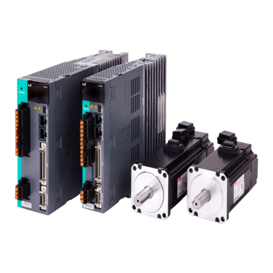
- Page 1 Xmotion L7P Series...
- Page 3 The reproduction of part or all of the contents of this manual in any form, by any means or for any purpose is strictly prohibited without the explicit written consent of LS ELECTRIC. LS ELECTRIC retains all patents, trademarks, copyrights and other intellectual property rights to the material in this manual.
- Page 4 Safety Precautions Safety precautions are categorized as either Danger or Cautions, depending on the severity of the precaution. Precautions Meaning Failure to comply with these guidelines may cause serious injury or death. Danger Failure to comply with these guidelines may cause personal injury or property Caution damage.
- Page 5 Installation Precautions Store and operate this product under the following environmental conditions. Conditions Environment Servo Drive Servo Motor 0 ~ 50 ℃ 0 ~ 40 ℃ Ambient -20 ~ 65 ℃ -10 ~ 60 ℃ temperature Storage temperature. Ambient humidity Below 90% RH (no condensation) 20~80% RH(no condensation)
- Page 6 Caution Install the product with the correct orientation. Do not drop the product or expose it to hard impact. Install this product in a location that is free from water, corrosive gas, combustible gas, or flammable materials. ...
- Page 7 Handling and Operating Precautions Caution Check and adjust each parameter before operation. Do not touch the rotating unit of the motor during operation. Do not touch the heat sink during operation. Be sure to attach or remove the I/O and ENCODER connectors when the power is off. ...
- Page 8 Product Application Caution This product is not designed or manufactured for machines or systems intended to sustain human life. This product is manufactured under strict quality control conditions. Nevertheless, install safety devices if installing the device in a facility where product malfunctions may result in a major accident or a significant loss.
-
Page 9: Table Of Contents
Table of Contents Product configuration ......... 1-1 Product Verification ......................1-1 Product Specifications ..................... 1-2 Part Names ........................1-4 1.3.1 Servo Drive Parts ................... 1-4 1.3.2 Servo Motor Parts ..................1-15 System configuration example ..................1-16 Product feature ........... 2-1 Servo Motor ........................ - Page 10 3.5.4 Names and Functions of Encoder Output Signals ........3-31 3.5.5 Examples of Connecting Input/Output Signals ..........3-32 3.5.6 Pulse string input signal................3-36 3.5.7 Connection diagram of I/O Signal ..............3-37 Encoder signal (ENCODER connector) wiring ............... 3-38 3.6.1 Option cable connection example ..............
- Page 11 Operation mode Change ........9-1 10. High speed homing .......... 10-1 10.1 Homing Method ......................10-2 11. Drive Application Function ....... 11-1 11.1 Drive Front Panel ......................11-1 11.1.1 7-Segment for indicating servo status ............11-1 11.1.2 Configuration of Drive Node Address ............11-4 11.1.3 Terminating resistor setting ................
- Page 12 12.3 Manual Gain Tuning ....................12-7 12.3.1 Gain Tuning Sequence ................. 12-7 12.4 Vibration Control ......................12-10 12.4.1 Notch Filter ....................12-10 12.4.2 Adaptive Filter ..................... 12-11 12.4.3 Vibration Control (Damping) Filter .............. 12-12 12.5 Analog Monitor ......................12-13 13. Procedure Function .......... 13-1 13.1 Manual JOG Operation ....................
- Page 13 16.2.1 Sending and receiving packet structure ............16-3 16.2.2 Protocol Command Code ................16-5 16.3 L7P Indexer Servo Drive Communication Address Table ........... 16-58 16.3.1 General Objects ..................16-58 16.3.2 System Configuration Parameters .............. 16-59 16.3.3 Control Parameters ..................16-61 16.3.4 Input and Output Parameters ..............
- Page 14 1. Product configuration...
-
Page 15: Product Configuration
1. Product configuration Product configuration Product Verification 1. Check the name tag to verify that the product received matches the model ordered Does the servo driver's name plate match? Does the servo motor's name plate match? 2. Check the product components and options. ... -
Page 16: Product Specifications
1. Product configuration Product Specifications L7P Series Product Type Series name Drive type Input voltage Capacity(200[V]) Capacity(400[V]) Encoder Option Standar 100[W] 1[kW] Universal Blank Standard I/O Marke Exclusi 200[W] 2[kW] 400[W] 3.5[kW] 800[W] 5.0[kW] Network A : 200[Vac] 1[kW] 7.5[kW] L series 2[kW]... - Page 17 1. Product configuration Servo Motor Product Format APM C – F E P 30 A M K 1 Input voltage Rated RPM SERVO MOTOR Option spec. Blank : 200Vac None : 3000 [rpm] : Not attached : 400Vac : 2000 [rpm] : Oil Seal attached : Brake attached : 1500 [rpm]...
-
Page 18: Part Names
1. Product configuration Part Names 1.3.1 Servo Drive Parts 100W, 200W, 400W (200[V]) Display Analog Monitor Connector Shows the status and alarms of the drive. Connector for monitoring of analog output signal Terminating Resistor Setting Node Address Switch When the switch is on, the drive’s internal This switch sets the drive’s node address. - Page 19 1. Product configuration 800W, 1kW (200[V]) Analog Monitor Connector Display window Connector for monitoring of analog output signal Shows the status and alarms of the drive Node Address Switch CHARGE Lamp This switch sets the drive’s node address. You Lamp lights up when the main circuit is powered can set node address at from 0 to 31 Terminating Resistor Setting Switch...
- Page 20 1. Product configuration 2kW, 3.5kW (200[V]) Analog Monitor Connector Display Window Connector for monitoring of analog Shows the status and alarms of the drive output signal Node Address Setting Switch CHARGE lamp This switch sets the drive’s node address. The lamp lights up when the main circuit is You can set node address at from 0 to 31 powered on.
- Page 21 1. Product configuration 5KW(200[V]) Connector for analog monitors Display It is a connector for checking the analog It shows drive status, alarms, etc. output signal. Terminating resistor setting switch Node address setting switch When the switch is On, the terminating This switch is to set the node address of resistance (120Ω) inside the drive is used.
- Page 22 1. Product configuration 7.5KW(200[V]) Display Connector for analog monitors It shows drive status, alarms, etc. It is a connector for checking the analog output signal. Terminating resistor setting switch Node address setting switch When the switch is On, the terminating This switch is to set the node address of resistor (120Ω) inside the drive is used.
- Page 23 1. Product configuration 15KW (200[V]) Display It shows drive status, alarms, etc. Connector for analog monitors It is a connector for checking the Terminating resistor setting switch analog output signal. When switch Node address setting switch terminating resistor (120Ω) inside the This switch is to set the node address drive is used.
- Page 24 1. Product configuration 1kW (400[V]) Analog monitor connector Display Connector to check analog output signals Shows drive status, alarms, etc. CHARGE lamp Node address setting switch Lights on when the main circuit power is on. Switch to set the node address of the drive. You can set the node addresses from 0 to 31.
- Page 25 1. Product configuration 2kW, 3.5kW (400[V]) Analog monitor connector Display Connector to check analog output signals Shows drive status, alarms, etc. Node address setting switch CHARGE lamp Switch to set the node address of the drive. Lights on when the main circuit power is on. You can set the node addresses from 0 to 31.
- Page 26 1. Product configuration 5KW(400[V]) Analog monitor connector Connector to check analog output signals Display Shows drive status, alarms, etc. Node address setting switch Switch to set the node address of the drive. Terminating resistor switch You can set the node addresses from 0 to 31. Turn on this switch to use the terminating resistor (120Ω) inside the drive.
- Page 27 1. Product configuration 7.5kW (400[V]) Analog monitor connector Connector to check analog output signals Display Shows drive status, alarms, etc. Node address setting switch Switch to set the node address of the drive. Terminating resistor switch You can set the node addresses from 0 to 31. Turn on this switch to use the terminating resistor (120Ω) inside the USB connectors (USB/Mini B type)
- Page 28 1. Product configuration 15kW (400[V]) Analog monitor connector Connector to check analog output signals Display Shows drive status, alarms, etc. Node address setting switch Switch to set the node address of the drive. You can set the node addresses from 0 to 31. Terminating resistor switch Turn on this switch to use the USB connectors (USB/Mini B type)
-
Page 29: Servo Motor Parts
1. Product configuration 1.3.2 Servo Motor Parts •80 Flange or less Motor Power Motor Cable Encoder Connector Connector Encoder Cable Encoder Cover Shaft Frame Flange Housing Bearing Cap •80 Flange or less (L series) Encoder connector Power connector Shaft Flange Frame Housing Encoder... -
Page 30: System Configuration Example
1. Product configuration System configuration example The figure below shows an example of system configuration using this drive. •200[V]/100[W] drive example Three-phase AC220V Handy Host device R S T loader Oscilloscope Circuit Breaker Shuts off the circuit when excessive current flows, to protect the power lines. -
Page 31: Product Feature
2. Product feature Product feature Servo Motor 2.1.1 Product feature ■ Heat Sink Spec. Classification Size(mm) Classification AP04 250x250x6 AP06 250x250x6 AP08 250x250x12 Aluminum AP13 350x350x20 AP18 550x550x30 AP22 650x650x35 ※ In the case of product specifications, it is the data measured after applying the heat sink. ※... - Page 32 2. Product feature ■ Procuct Features [200V] SAR3A SAR5A SA01A SA015A Servo Motor Name (APM- Applicable Drive (L7□A□□) L7□A001 L7□A002 Rated output [kW] 0.03 0.05 0.10 0.15 [N⋅m] 0.10 0.16 0.32 0.48 Rated torque [kgf⋅cm] 0.97 1.62 3.25 4.87 0.29 0.48 0.96 1.43...
- Page 33 2. Product feature ■ Procuct Features [200V] SB01A SB02A SB04A Servo Motor Name (APM- Applicable Drive (L7□A□□) L7□A002 L7□A004 Rated output [kW] 0.10 0.20 0.40 0.32 0.64 1.27 [N⋅m] Rated torque [kgf⋅cm] 3.25 6.49 12.99 [N⋅m] 0.96 1.91 3.82 Instantaneous maximum torque [kgf⋅cm] 9.74...
- Page 34 2. Product feature ■ Procuct Features [200V] SC04A SC06A SC08A SC10A Servo Motor Name (APM- Applicable Drive (L7□A□□) L7□A004 L7□A008 L7□A010 Rated output [kW] [N⋅m] 1.27 1.91 2.55 3.19 Rated torque [kgf⋅cm] 12.99 19.49 25.98 32.48 3.82 5.73 7.64 9.56 [N⋅m] Instantaneous maximum torque...
- Page 35 2. Product feature ■ Procuct Features [200V] SC03D SC05D SC06D SC07D Servo Motor Name (APM- Applicable Drive (L7□A□□) L7□A004 L7□A008 Rated output [kW] 0.30 0.45 0.55 0.65 [N⋅m] 1.43 2.15 2.63 3.10 Rated torque [kgf⋅cm] 14.61 21.92 26.79 31.66 4.30 6.45 7.88 9.31...
- Page 36 2. Product feature ■ Procuct Features [200V] Servo Motor Name (APM- FALR5A FAL01A FAL015A FBL01A FBL02A FBL04A Applicable Drive (L7□A□□) L7□A001 L7□A002 L7□A001 L7□A002 L7□A004 Rated output [kW] 0.05 0.10 0.15 0.10 0.20 0.40 [N⋅m] 0.16 0.32 0.48 0.32 0.64 1.27 Rated torque 1.62...
- Page 37 2. Product feature ■ Procuct Features [200V] FCL04A FCL06A FCL08A FCL10A Servo Motor Name (APM- Applicable Drive (L7□A□□) L7□A004 L7□A008 L7□A010 Rated output [kW] 0.40 0.60 0.75 1.00 [N⋅m] 1.27 1.91 2.39 3.18 Rated torque [kgf⋅cm] 12.99 19.49 24.36 32.48 [N⋅m] 3.82 5.73...
- Page 38 2. Product feature ■ Procuct Features [200V] FCL03D FCL05D FCL06D FCL07D Servo Motor Name (APM- Applicable Drive (L7□A□□) L7□A004 L7□A008 Rated output [kW] 0.30 0.45 0.55 0.65 [N⋅m] 1.43 2.15 2.63 3.10 Rated torque [kgf⋅cm] 14.62 21.92 26.80 31.67 [N⋅m] Instantaneous 4.30 6.45...
- Page 39 2. Product feature ■ Procuct Features [200V] HB01A HB02A HB04A HE09A HE15A HE30A Servo Motor Name (APM- Applicable Drive (L7□A□□) L7□A002 L7□A004 L7□A008 L7□A020 L7□A035 Rated output [kW] 0.32 0.64 1.27 2.86 4.77 [N⋅m] 9.55 Rated torque [kgf⋅cm] 3.25 6.49 12.99 29.23 48.72...
- Page 40 2. Product feature ■ Procuct Features [200V] FE09A FE15A FE22A FE30A Servo Motor Name (APM- Applicable Drive (L7□A□□) L7□A010 L7□A020 L7□A035 Rated output [kW] [N⋅m] 2.86 4.77 7.00 9.55 Rated torque 29.20 48.70 71.40 97.40 [kgf⋅cm] [N⋅m] 8.59 14.32 21.01 28.65 Instantaneous maximum torque...
- Page 41 2. Product feature ■ Procuct Features [200V] FE06D FE11D FE16D FE22D Servo Motor Name (APM- L7□A008 L7□A010 L7□A020 Applicable Drive (L7□A□□) Rated output [kW] [N⋅m] 2.86 5.25 7.63 10.5 Rated torque 29.2/0 53.60 77.90 107.10 [kgf⋅cm] [N⋅m] 8.59 15.75 22.92 31.51 Instantaneous maximum torque...
- Page 42 2. Product feature ■ Procuct Features [200V] FE05G FE09G FE13G FE17G Servo Motor Name (APM- Applicable Drive (L7□A□□) L7□A008 L7□A010 L7□A020 Rated output [kW] 0.45 0.85 2.86 5.41 8.27 10.82 [N⋅m] Rated torque [kgf⋅cm] 29.22 55.19 84.41 110.38 8.59 16.23 24.82 32.46 [N⋅m]...
- Page 43 2. Product feature ■ Procuct Features [200V] FE03M FE06M FE09M FE12M Servo Motor Name (APM- L7□A004 L7□A008 L7□A010 L7□A020 Applicable Drive (L7□A□□) Rated output [kW] [N⋅m] 2.86 5.72 8.59 11.46 Rated torque 29.22 58.4 87.7 116.9 [kgf⋅cm] [N⋅m] 8.59 17.18 25.77 34.22 Instantaneous...
- Page 44 2. Product feature ■ Procuct Features [200V] FF30A FF50A FF22D FF35D FF55D FF75D Servo Motor Name (APM- L7□A035 L7□A050 L7□A020 L7□A035 L7□A050 L7□A075B Applicable Drive (L7□A□□) Rated output [kW] [N⋅m] 9.55 15.91 10.50 16.70 26.25 35.81 Rated torque 97.40 162.30 107.1 170.4 267.8...
- Page 45 2. Product feature ■ Procuct Features [200V] FF20G FF30G FF44G FF60G FF75G Servo Motor Name (APM- Applicable Drive (L7□A□□) L7□A020 L7□A035 L7□A050 L7□A075B Rated output [kW] [N⋅m] 11.45 18.46 28.00 38.20 47.70 Rated torque 116.9 188.3 285.7 [kgf⋅cm] 389.80 487.20 [N⋅m] 34.35 55.38...
- Page 46 2. Product feature ■ Procuct Features [200V] FF12M FF20M FF30M FF44M Servo Motor Name (APM- L7□A020 L7□A035 L7□A050 Applicable Drive (L7□A□□) Rated output [kW] [N⋅m] 11.46 19.09 28.64 42.02 Rated torque 116.9 194.8 292.2 428.7 [kgf⋅cm] [N⋅m] 34.38 57.29 85.94 105.05 Instantaneous maximum torque...
- Page 47 2. Product feature ■ Procuct Features [200V] FG22D FG35D FG55D FG75D FG110D Servo Motor Name (APM- Applicable Drive (L7□A□□) L7□A020 L7□A035 L7□A050 L7□A075B L7□A150B Rated output [kW] [N⋅m] 10.50 16.71 26.25 35.81 52.52 Rated torque 107.1 170.4 267.8 365.4 525.9 [kgf⋅cm] [N⋅m] 31.51...
- Page 48 2. Product feature ■ Procuct Features [200V] FG20G FG30G FG44G FG60G FG85G FG110G FG150G Servo Motor Name (APM- Applicable Drive (L7□A□□) L7□A020 L7□A035 L7□A050 L7□A075 L7□A150B Rated output [kW] [N⋅m] 11.50 18.50 28.00 38.2 54.11 69.99 95.45 Rated torque 116.9 188.4 285.8 389.7...
- Page 49 2. Product feature ■ Procuct Features [200V] FG12M FG20M FG30M FG44M FG60M Servo Motor Name (APM- Applicable Drive (L7□A□□) L7□A020 L7□A035 L7□A050 Rated output [kW] [N⋅m] 11.50 19.10 28.60 42.00 57.29 Rated torque 116.9 194.9 292.3 428.7 584.6 [kgf⋅cm] [N⋅m] 34.40 57.30 85.90...
-
Page 50: Product Feature
2. Product feature ■ Procuct Features [400V] FEP09A FEP15A FEP22A FEP30A Servo Motor Name (APM- L7□B010□ L7□B020□ L7□B035□ Applicable Drive(L7 A Rated output [kW] [N⋅m] 2.86 4.77 7.00 9.55 Rated torque 29.23 48.72 71.46 97.44 [kgf⋅cm] [N⋅m] 8.59 14.32 21.01 28.65 Instantaneous maximum torque... - Page 51 2. Product feature ■ Procuct Features [400V] FEP06D FEP11D FEP16D FEP22D Servo Motor Name (APM- Applicable Drive(L7 A L7□B010□ L7□B020□ Rated output [kW] 2.86 5.25 7.64 10.5 [N⋅m] Rated torque [kgf⋅cm] 29.23 53.59 77.95 107.19 8.59 15.76 22.92 31.51 [N⋅m] Instantaneous maximum torque [kgf⋅cm]...
- Page 52 2. Product feature ■ Procuct Features [400V] FEP05G FEP09G FEP13G FEP17G Servo Motor Name (APM- L7□B010□ L7□B020□ Applicable Drive(L7 A Rated output [kW] 0.45 0.85 [N⋅m] 2.86 5.41 8.28 10.82 Rated torque 29.23 55.22 84.45 110.43 [kgf⋅cm] [N⋅m] 8.59 16.23 24.83 32.47 Instantaneous...
- Page 53 2. Product feature ■ Procuct Features [400V] Servo Motor Name (APM- FEP03M FEP06M FEP09M FEP12M L7□B010□ L7□B035□ Applicable Drive(L7 A Rated output [kW] 2.86 5.73 8.59 11.46 [N⋅m] Rated torque [kgf⋅cm] 29.23 58.47 87.70 116.93 8.59 17.19 25.78 34.38 [N⋅m] Instantaneous maximum torque 87.70...
- Page 54 2. Product feature ■ Procuct Features [400V] FFP30A FFP50A FFP22D FFP35D FFP55D FFP75D Servo Motor Name (APM- L7□B035□ L7□B075□ L7□B020□ L7□B035□ L7□B050□ L7□B075□ Applicable Drive(L7 A Rated output [kW] [N⋅m] 9.55 15.92 10.50 16.71 26.26 35.81 Rated torque 97.44 162.40 107.19 170.52 267.96...
- Page 55 2. Product feature ■ Procuct Features [400V] FFP20G FFP30G FFP44G FFP60G FFP75G Servo Motor Name (APM- L7□B020□ L7□B035□ L7□B050□ L7□B075□ Applicable Drive(L7 A Rated output [kW] [N⋅m] 11.46 18.46 28.01 38.20 47.75 Rated torque 116.93 188.39 285.83 389.77 [kgf⋅cm] 487.21 [N⋅m] 34.38 55.39...
- Page 56 2. Product feature ■ Procuct Features [400V] FFP12M FFP20M FFP30M FFP44M Servo Motor Name (APM- Applicable Drive(L7 A L7□B020□ L7□B050□ L7□B050□ Rated output [kW] [N⋅m] 11.46 19.10 28.65 42.02 Rated torque [kgf⋅cm] 116.93 194.88 292.33 428.74 [N⋅m] Instantaneous 34.38 57.30 71.62 105.05 maximum torque...
- Page 57 2. Product feature ■ Procuct Features [400V] FGP22D FGP35D FGP55D FGP75D FGP110D Servo Motor Name (APM- L7□B020□ L7□B035□ L7□B050□ L7□B075□ L7□B150□ Applicable Drive(L7 A Rated output [kW] 11.0 [N⋅m] 52.52 10.50 16.71 26.26 35.81 Rated torque 525.9 [kgf⋅cm] 107.19 170.52 267.96 365.41 [N⋅m]...
- Page 58 2. Product feature ■ Procuct Features [400V] FGP20G FGP30G FGP44G FGP60G FGP85G FGP110G FGP150G Servo Motor Name (APM- Applicable Drive(L7 A L7□B020□ L7□B035□ L7□B050□ L7□B075□ L7□B150□ Rated output [kW] 11.0 15.0 [N⋅m] 11.46 18.46 28.01 38.20 54.11 70.03 95.49 Rated torque [kgf⋅cm] 116.93 188.39...
- Page 59 2. Product feature ■ Procuct Features [400V] FGP12M Servo Motor Name (APM- FGP20M FGP30M FGP44M FGP60M Applicable Drive(L7 A L7□B020□ L7□B035□ L7□B050□ L7□B075□ Rated output [kW] [N⋅m] 11.46 19.10 28.65 42.02 57.30 Rated torque [kgf⋅cm] 116.93 194.88 292.33 428.74 584.65 [N⋅m] Instantaneous 34.38...
- Page 60 2. Product feature ■ Electric brake specification Applicable FG(P)110G motor series FG(P)150G For retain Usage For retain For retain For retain For retain For retain For retain Input voltage(V) DC 24V DC 24V DC 24V DC 24V DC 24V DC 90V DC 24V Static friction 0.32...
-
Page 61: Outline Drawing
2. Product feature 2.1.2 Outline drawing ■ SA Series | APM-SAR3A, SAR5A, SA01A, SA015A "CB±0.5" 0.04 44.2±0.5 0.04 23.8±0.5 2-Ø4.5 4-R3 PCD 46±0.12 "LC" 36.5 0.02 "LM±0.5" "L±0.5" <Power Connector> <Brake Connector> <Encoder Connector> Signal Signal Signal Signal Pin No. Pin No. - Page 62 2. Product feature ■ SB Series | APM-SB01A, SB02A, SB04A "CB±0.5" 0.04 31.2±0.5 4-Ø6 PCD 70±0.12 0.04 22.5 0.02 "LC" 40.2 "LM±0.5" "L±0.5" <Shaft type <Power Connector> <Brake Connector> <Encoder Connector> Signal Signal Signal Signal Pin No. Pin No. Pin No. Pin No.
- Page 63 2. Product feature ■ SC Series | APM-SC04A, SC03D, SC06A, SC05D, SC08A, SC06D, SC10A, SC07D "CB±0.5" 0.04 27.5 20±0.5 4-Ø6.6 0.04 PCD90±0.12 0.02 "LC" 40.5 "LM±0.5" "L±0.5" <Shaft type <Power Connector> <Brake Connector> <Encoder Connector> Signal Signal Signal Signal Pin No. Pin No.
- Page 64 2. Product feature ■ FAL Series | APM – FALR5A APM – FAL01A APM – FAL015A Encoder Connector Brake Connector Power Connector 2-Ø4.5 PCD46±0.12 0.04 A "LA" "LC" 36.4 0.04 0.04 A "LM±0.5" "L±0.5" Signal Multi Turn (M) Pin No. name Signal Signal...
- Page 65 2. Product feature ■ FBL Series | APM – FBL01A, FBL02A, FBL04A "W" 9° (Shaft End Dimension Detail) Brake Connector Encoder Connector Power Connector 4-Ø6 PCD 70±0.12 0.04 A 22.5 0.04 "LC" 40.2 "LM±0.5" 0.04 A "L±0.5" <When the cable is pulled out in the opposite direction of the axis> Signal Multi Turn (M) Pin No.
- Page 66 2. Product feature ■ FCL Series | APM - FCL04A, FCL03D, FCL06A, FCL05D APM - FCL08A, FCL06D, FCL10A, FCL07D "W" 9° Brake Connector Encoder Connector Power Connector 4-Ø6.6 PCD 90±0.12 0.04 A Ø 0.04 "LC" 40.5 0.04 A "LM±0.5" "L±0.5" <When the cable withdrawal direction is opposite to the axis>...
- Page 67 2. Product feature ■ HB Series | APM-HB01A (Hollow Shaft) APM-HB02A (Hollow Shaft) APM-HB04A (Hollow Shaft) "CB" 49.5 0.04 A 4-Ø6 0.04 A PCD 70±0.12 Ø C0.5 "LC" 0.04 "LM" "L±0.1" <Power Connector> <Encoder Connector> Signal Signal Signal Pin No. Pin No.
- Page 68 2. Product feature ■ HE Series | APM-HE09A (Hollow Shaft) APM-HE15A (Hollow Shaft) APM-HE30A (Hollow Shaft) 6-M5 Tap, depth 10 PCD52±0.12 4-Ø9 PCD145±0.15 0.05 A 0.02 0.02 60° "LC" 38.5 0.05A "LM" "L" <Power Connector> <Encoder Connector> Signal Signal Signal Pin No.
- Page 69 2. Product feature ■FE(P) Series | APM-FE(P)09A, FE(P)06D, FE(P)05G, FE(P)03M, FE(P)15A, FE(P)11D, FE(P)09G, FE(P)06M APM-FE(P)22A, FE(P)16D, FE(P)13G, FE(P)09M, FE(P)30A, FE(P)22D, FE(P)17G, FE(P)12M 4-∅9 PCD145±0.15 0.04 A 0.02 "LC" 38.2 0.04 A "W" "LM±0.5" "L±0.5" <Power Connector> <Brake Type Connector> Signal Pin No.
- Page 70 2. Product feature ■ FF(P) Series | APM-FF(P)30A, FF(P)22D, FF(P)20G, FF(P)12M, FF(P)50A, FF(P)35D, FF(P)30G, FF(P)20M, APM-FF(P)55D, FF(P)44G, FF(P)30M, FF(P)75D, FF(P)60G, FF(P)44M, FF(P)75G 72.2±0.5 4-Ø13.5 PCD200±0.15 0.04 A "QW" 0.02 "LC" 51.7 0.04 A "LR" "LM±0.5" "W" "L±0.5" (Detail of dimensions) <Power Connector>...
- Page 71 2. Product feature ■FG(P) Series | APM-FG(P)22D, FG(P)20G, FG(P)12M, FG(P)35D, FG(P)30G, FG(P)20M, FG(P)55D, FG(P)44G APM- FG(P)30M, FG(P)75D, FG(P)60G, FG(P)44M, FG(P)110D, FG(P)85G, FG(P)60M 20.5±0.5 4-M8 Tap 4-∅13.5 PCD252±0.5 0.04 A PCD235±0.2 90° Equal interval Ø 0.02 "LF" "LC±0.5" "W" 0.04 A "LM±0.5"...
- Page 72 2. Product feature ■ FG(P) Series | APM-FG(P)110G 4-M8 Tap, DP18 4-Ø13.5 thru PCD252±0.2 PCD235±0.2 90° 0.02 A 0.02 "L 0.02 A "L± M12 Tap, DP25 <Power Connector> <Brake Connector> Signal Pin No. Polar name Pin No. Plug : MS3102A32-17P Plug : MS3102A14-7P <Serial M-Turn Connector>...
- Page 73 2. Product feature ■ FG(P) Series | APM-FG(P)150G 4-∅13.5 4-M8, Tap PCD235±0.2 PCD252±0.15 20.5±0.5 0.04 A 0.02 "LC" `` A "LM±0.5" "L±0.5" M12 Tap, DP25 <Power Connector> <Brake Connector> Signal Pin No. Polar name Pin No. Plug : MS3102A32-17P Plug : MS3102A14-7P <Serial M-Turn Connector>...
-
Page 74: Servo Drive
2. Product feature Servo Drive 2.2.1 Product Features 200[V] Model name L7PA0 L7PA0 L7PA0 L7PA0 L7PA0 L7PA0 L7PA0 L7PA0 L7PA0 L7PA1 Item Three-phase AC200 ~ 230[V](-15 ~ +10[%]), 50 ~ 60[Hz] Main power Input Single-phase AC200 ~ 230[V](-15 ~ +10[%]), 50 ~ 60[Hz] Control power power Rated current [A]... - Page 75 2. Product feature Note) * Default allocation signal. Rated voltage and current: DC 24 V ± 10%, 120 ㎃ A total of 8 input channels (allocable) You can selectively allocate 19 kinds of output. Digital output (*ALARM±, *READY±, *BRAKE±, *INPOS1±, *ORG±, *EOS±, *TGON±, *TLMT±, VLMT±, INSPD±, ZSPD±, WARN±, INPOS2±, IOUT0±, IOUT1±, IOUT2±...
- Page 76 2. Product feature 400[V] Model name L7PB010U LPB020U L7PB035U L7PB050U L7PB075U L7PB150U Item Main power Three-phase AC380 ~ 480[V](-15 ~ +10[%]), 50 ~ 60[Hz] Input power Control power Single-phase AC380 ~ 480[V](-15 ~ +10[%]), 50 ~ 60[Hz] Rated current [A] 10.1 17.5 22.8...
- Page 77 2. Product feature Rated voltage and current: DC 24 V ± 10%, 120 ㎃ A total 8 input channels (allocable) You can selectively allocate 19 kinds of output. Digital output (*ALARM±, *READY±, *BRAKE±, *INPOS1±, *ORG±, *EOS±, *TGON±, *TLMT±, VLMT±, INSPD±, ZSPD±, WARN±, INPOS2±, IOUT0±, IOUT1±, IOUT2± IOUT3±, IOUT4±, IOUT5±) Note) * Default allocation signal.
-
Page 78: Outline Drawing
2. Product feature 2.2.2 Outline drawing L7PA001U ~ L7PA004U ★ Weight: 1.0[kg] L7PA008U / L7PA010U ★ Weight: 1.5[kg] (including cooling pan) 2-48... - Page 79 2. Product feature L7PA020U / L7PA035U ★ Weight: 1.5[kg] (including cooling pan) L7PA050U ★ Weight: 5.5[kg] (including cooling pan) 2-49...
- Page 80 2. Product feature L7PA075U ★ Weight: 9.7[kg] (including cooling pan) L7PA150U 12.5 101.6 ★ Weight: 16.2[kg] (including cooling pan) 2-50...
- Page 81 2. Product feature L7PB010U 1.5[kg] (including cooling pan) L7PB020U / L7PB035U *Weight: 2.5[kg] (including cooling pan) 2-51...
- Page 82 2. Product feature L7NHB050U *Weight: 5.5[kg] (including cooling pan) L7NHB075U *Weight: 8.5[kg] (including cooling pan) 2-52...
- Page 83 2. Product feature L7PB150U *Weight: 15.5[kg] (including cooling pan) 2-53...
-
Page 84: Options And Peripheral Devices
2. Product feature Options and Peripheral Devices ■ Option (Incremental encoder cable) Product Small capacity AMP Type INC encoder cable Classification For signal name Product Applicable APCS- E All model of APM-SA/SB/SC/HB SERIES INC name Motors (*Note 1) Motor Side Connector Drive Side Connector Encoder Encoder... - Page 85 2. Product feature ■ Option [serial encoder cable] Classificat Product Small capacity AMP Type serial encoder cable For signal (single turn) name Product Applicabl name APCS- E All model of APM-SB/SC SERIES S-turn e Motors (*Note 1) Motor Side Connector Drive Side Connector L7 Biss Encoder...
- Page 86 2. Product feature ■ Option [serial encoder cable] Classificat Product Small capacity Flat type motor serial encoder For signal cable(multi turn) name Product APCS- E ES1(Front Direction)/ Applicabl name All model of APM-FAL/FBL/FCL SERIES M-turn e Motors APCS- E ES1-R(Rear Direction) (*Note 1) Motor Side Connector Drive Side Connector...
- Page 87 2. Product feature ■ Option [serial encoder cable] Classificat Product Medium-large capacity MS Type serial For signal encoder cable (multi turn) name Product Applicabl All models of APM-FE(P)/FF(P)/FG(P) name APCS- E e Motors SERIES M-turn (*Note 1) Motor Side Connector Drive Side Connector Encoder Encoder...
- Page 88 2. Product feature ■ [200V] Option (Standard power cable) Product Classification Power Small capacity AMP Type power cable name Product Applicable All model of APM-SA/SB/SC/HB SERIES APCS- P name Motors (*Note 1) Motor Side Connector Drive Side Connector Product name Pin No.
- Page 89 2. Product feature ■ [200V] Option (Standard power cable) Product Medium capacity MS Type power cable(for 130 Classification Power Flange) name Product Applicable All model of APM-FE/HE SERIES APCS- P name Motors (*Note 1) Motor Side Connector Drive Side Connector Product name Pin No.
- Page 90 2. Product feature ■ [200V] Option (Standard power cable) Product Medium capacity MS Type power cable(180/ 220 Classification Power Flange) name FF30A, FF22D, FF35D, FF20G, FF30G,FF12M, FF20M, Product Applicable FF30M APCS- P name Motors (*Note 1) FG22D, FG35D, FG20G, FG12M, FG20M, FG30M Motor Side Connector Drive Side Connector Product...
- Page 91 2. Product feature ■ [200V] Option (Standard power cable) Classificatio Product Medium capacity MS Type power cable(180/ 220 Power Flange) name Product Applicable FF50A, FF55D, FF44G, FF44M, FG55D, FG44G, FG44M APCS- P name Motors (*Note 1) Motor Side Connector Drive Side Connector Name Phase Pin No.
- Page 92 2. Product feature ■ [200V] Option (Standard power cable) Product Medium capacity MS Type power cable(for 220 Classification Power Flange) name Product Applicable FG60M, FG75G APCS- P name Motors (*Note 1) Motor Side Connector Drive Side Connector Name Phase Pin No. Specification LEAD WIRE...
- Page 93 2. Product feature ■ [200V] Option (Standard power cable) Product Medium capacity MS Type power cable(for 220 Classification Power Flange) name Product name Applicable FG150G APCS- P Motors (*Note 1) Motor Side Connector Drive Side Connector Name Phase Pin No. Specification LEAD WIRE...
- Page 94 2. Product feature ■ [200V] Options spec. (small capacity L Series power cable) Product Classification Power Small capacity L Series power cable name Product Applicable APCS- P LS(Front Direction)/ All model of APM- FAL/ FBL/FCL Series name APCS- P LS-R(Rear Direction) Motors (*Note 1) Motor Side Connector...
- Page 95 2. Product feature ■ [400V] Option (Standard power cable) Classificatio Product Medium capacity MS Type power cable(for 130 Power Flange) name Product Applicable All model of APM-FEP SERIES APCF- P name Motors (*Note 1) Motor Side Connector Drive Side Connector Product name Pin No.
- Page 96 2. Product feature ■ [400V] Option (Standard power cable) Classificatio Product Medium capacity MS Type power cable(180/ 220 Power Flange) name FFP30A, FFP22D, FFP35D, FFP20G, FFP30G, Product Applicable FFP12M, FFP20M, APCF- P FGP22D, FGP35D, FGP20G, FGP30G FGP12M, name Motors (*Note 1) FGP20M Motor Side Connector Drive Side Connector...
- Page 97 2. Product feature ■ [400V] Option (Standard power cable) Classificatio Product Medium capacity MS Type power cable(180/ 220 Power Flange) name FFP50A, FFP55D, FFP75D, FFP44G, FFP60G, Product Applicable FFP30M, FFP44M, APCF- P FGP55D, FGP75D, FGP44G, FGP60G, FGP30M, name Motors (*Note 1) FGP44M Motor Side Connector Drive Side Connector...
- Page 98 2. Product feature ■ [400V] Option (Standard power cable) Product Medium capacity MS Type power cable(for 220 Classification Power Flange) name Product Applicable FFP75G, FGP110D, FGP85G, FGP110G, FGP150G, APCF- P FGP60M name Motors (*Note 1) Motor Side Connector Drive Side Connector Name Phase Pin No.
- Page 99 2. Product feature ■ Options spec. (cable) Class Product Product Applicable ificati name name (*Note drive Specification [Drive connection I/O] [Upper level Pin number 1. Drive connection(I/O) a. Case spec.: 10350-52A0-008(3M) b. CONNECTOR spec.: 10150-3000VE(3M ) c. CABLE spec.: ROW-SB0.1Cx50C(AWG 28) wire wire wire...
- Page 100 2. Product feature ■ Option spec. (connector) Class Product Model name Applicable name drive ificati Specification Cable length=0.5m For I/O APC-VSCN1T L7 SERIES APC-VPCN1T 1. APC-VSCN1T: CN1 T/B extended type of APD- a. APC-VPCN1T: CN1 T/B extended type of APD-VP b.
- Page 101 2. Product feature Option spec.(Braking resistance) / 200[V] Class Product Model name Applicable name drive ificati Specification L7□A001□ resista Brake APCS-140R50 L7□A002□ resistance L7□A004□ L7□A008□ resista Brake APCS-300R30 resistance L7□A010□ L7□A020□ (2P) resista Brake APC-600R30 resistance L7□A035□ (3P) L7□A050□ resista Brake APC-600R28 L7□A075□...
- Page 102 2. Product feature Option (Braking resistance) / 400[V] Class Product Model name Applicable ificati Name drive Specification resista Brake APCS-300R82 L7□B010□ resistance L7□B020□ APCS-600R140 resista Brake /L□PB035□ resistance (600W x 2P) (2P) L7□B050□ APCS-600R75 resista Brake /L7□B075□ resistance (600W x 3P) (3P) resista Brake...
- Page 103 2. Product feature ■ Option (Noise filter) Classifi Product Model Applicable Specification cation name name drive L7□A 001□ L7□A 002□ L7□A 004□ APCS-TB6- L7□A 008□ B010LBEI L7□A 010□ L7□B 010□ L7□B 020□ APCS-TB6- L7□B 035□ B020NBDC L7□A 020□ L7□A 035□ APCS-TB6- B030NBDC resistanc...
- Page 104 2. Product feature 2-74...
-
Page 105: Wiring And Connection
3. Wiring and Connection Wiring and Connection Installation of Servo Motor Caution If the encoder loses multi-turn data, there is a risk of equipment malfunction or accident. Therefore, be sure to operate after homing. When using an absolute encoder, the multi-turn data of the encoder is lost in the following process. -
Page 106: Motor Connection
3. Wiring and Connection 3.1.3 Motor Connection Servo Motor If the motor is directly connected to commercial power, it may be burned. Be sure to connect with the specified drive before using it. Connect the ground terminals of the motor to either of the two ground terminals inside the drive, and attach the remaining terminal to the type-3 ground. -
Page 107: The Load Device Connection
3. Wiring and Connection 3.1.4 The Load Device Connection For coupling connections: Install the motor shaft and the load shaft so that they match within the allowable range. 0.03 ㎜ or less (peak to peak) Load shaft Motor shaft 0.03 ㎜ or less (peak to peak) ... -
Page 108: Installation Of The Servo Drive
3. Wiring and Connection Installation of the Servo Drive 3.2.1 Installation and Usage Environment Environmental Item Remarks conditions Caution Operating ambient 0∼50[℃] Install a cooling fan on the control panel to maintain an temperature appropriate temperature. Caution Condensation or moisture may develop inside the drive during Ambient 90% RH or lower prolonged periods of inactivity and damage it. -
Page 109: Installation In The Control Panel
3. Wiring and Connection 3.2.2 Installation in the Control panel The installation interval in the control panel is as shown in the figure below. In case of 1 unit installation 40mm or more 10mm 10mm or more or more 40mm or more... - Page 110 3. Wiring and Connection In case of installation of 2 or more units Install a cooling fan on the top of the servo drive to prevent the internal temperature of the control panel from exceeding the environmental conditions of the servo drive. Also, leave enough space while referring to the figure below to allow cooling by heat convection within the fan and control panel.
-
Page 111: Internal Block Diagram Of Drive
3. Wiring and Connection Internal Block Diagram of Drive 3.3.1 Block Diagram of Drive (100W~400W/200[V]) Note1) Note2) Thermistor Diode IGBT 3-Phase power input Current Regenerative sensor AC200~230V resistor Thermistor Chage Lamp T1 T2 Thermistor Regenerative IGBT temp. Internal temp. PWM signal U,V current Main power DC voltage... -
Page 112: Block Diagram Of Drive (800W~3.5Kw/200[V])
3. Wiring and Connection 3.3.2 Block Diagram of Drive (800W~3.5kW/200[V]) Note1) Note2) Note3) Thermistor Diode IGBT 3-phase power input Current Regenerative sensor AC200~230V resistor Thermistor Chage Lamp T1 T2 Thermistor Note4) DC voltage Main power phase Regenerative IGBT temp. Control power phase U,V current DB drive PWM signal... -
Page 113: Block Diagram Of Drive (5Kw~7.5Kw/200[V])
3. Wiring and Connection 3.3.3 Block Diagram of Drive (5kW~7.5kW/200[V]) Note1) Note2) External Regenerative Note3) resistor Thermistor Diode IGBT 3-phase power input Current sensor AC200~230V Thermistor Chage Lamp T1 T2 Thermistor Note4) DC voltage Main power phase Regenerative IGBT temp. Control power phase U,V current DB drive... -
Page 114: Block Diagram Of Drive (15Kw / 200[V])
3. Wiring and Connection 3.3.4 Block Diagram of drive (15kW / 200[V]) Note1) Note2) External Regenerative Note3) resistor Thermistor Diode IGBT 3-phase power input Current sensor AC200~230V Thermistor Chage Lamp T1 T2 Thermistor Note4) Main power phase DC voltage Regenerative IGBT temp. -
Page 115: Block Diagram Of Drive (1Kw~3.5Kw/400[V])
3. Wiring and Connection 3.3.5 Block Diagram of Drive (1kW~3.5kW/400[V]) Note1) Note2) Diode Thermistor Note3) IGBT 3-Phase power input Current Regenerative sensor AC380~480V resistor Thermistor Chage Lamp Thermistor Note 4) N Regenerative IGBT temp. U,V current Internal temp. PWM signal Main power DC voltage Control power phase... -
Page 116: Block Diagram Of Drive (5Kw~7.5Kw/400[V])
3. Wiring and Connection 3.3.6 Block Diagram of Drive (5kW~7.5kW/400[V]) Note1) Note2) Diode Thermistor Note3) IGBT 3-Phase power input Current Regenerative sensor AC380~480V resistor Thermistor Chage Lamp T1 T2 Thermistor Note 4) N Regenerative IGBT temp. U,V current Internal temp. PWM signal Main power DC voltage... -
Page 117: Block Diagram Of Drive (15Kw/400[V])
3. Wiring and Connection 3.3.7 Block Diagram of Drive (15kW/400[V]) Note2) External Regenerative Note1) Note3) resistor Thermistor Diode IGBT 3-phase power input Current sensor AC380~480V Thermistor Chage Lamp T1 T2 Thermistor Note4) DC voltage Main power phase Regenerative IGBT temp. Control power phase U,V current DB drive... -
Page 118: Power Supply Wiring
3. Wiring and Connection Power Supply Wiring Ensure that the input power voltage is within the acceptable range. Caution Overvoltages can damage the drive. If commercial power is connected to U, V, W terminals of Drive, they may be damaged. Be sure to connect power to L1, L2, L3 terminals. - Page 119 3. Wiring and Connection 3.4.1 Power Supply Wiring [100W~3.5kW](200/400[V]) 200[V]:AC 220~230[V] 400[V]:AC 380~480[V] Servo drive Note1) DC Reactor Note2) Main Main PO PI Note5) Encoder Alarm+ +24V Alarm- Note3) External regenerative resistor Note1) It takes approximately one to two seconds until alarm signal is output after you turn on the main power.
- Page 120 3. Wiring and Connection [5kW~7.5kW](200/400[V]) 200[V]:AC 220~230[V] 400[V]:AC 380~480[V] Servo drive Note1) DC Reactor Note2) Main Main PO PI Note5) Encoder Alarm+ +24V Alarm- Note3) External regenerative resistor Note1) It takes approximately one to two seconds until alarm signal is output after you turn on the main power.
- Page 121 3. Wiring and Connection [15kW](200/400[V]) 200[V]:AC 220~230[V] 400[V]:AC 380~480[V] Servo drive Note1) DC Reactor Note2) Main Main PO PI Note5) Encoder Alarm+ +24V Alarm- Note3) External regenerative resistor Note1) It takes approximately two to three seconds until alarm signal is output after you turn on the main power.
-
Page 122: Power Supply Sequence
3. Wiring and Connection 3.4.2 Power supply sequence Power supply sequence For power wiring, use a magnetic contactor for the main circuit power as shown in 2.4.1 Power Supply Wiring Diagram. Configure the magnetic contactor to turn off at the same time an alarm occurs in an external sequence. -
Page 123: Power Circuit Electrical Components
3. Wiring and Connection 3.4.3 Power circuit Electrical Components 200[V] L7PA050U L7PA075U L7PA150U Model name L7PA001U~L7PA010U L7PA020U~L7PA035U 30A Frame 50A Frame 50A Frame 100A Frame 30A Frame 15A MCCB(NFB) 100A (ABE33C/15) (ABE33C/30) (ABE53b/40) (ABE53b/50) (ABS103/100) TB6- TB6- Noise Filter TB6-B010LBEI(10A) TB6-B030NBDC(30A) B060LA(60A (NF) - Page 124 3. Wiring and Connection 400[V] L7PB050U Model name L7PB010U L7PB020U~L7PB035U L7PB075U L7PB150U 30A Frame 50A Frame 30A Frame 10A 30A Frame 30A 30A Frame 30A MCCB (ABE33b/10) (ABE33b/30) (ABE33b/30) (ABE33b/20) (ABE53b/50) TB6- TB6- TB6- TB6-B030NBDC TB6-B010LBEI Noise Filter (NF) B020NBDC B040A B060LA (10A)
- Page 125 3. Wiring and Connection L7NHA004U or lower Wire strip 7~10[mm] Weidmuller SD 0.6×3.5×100 M4: 1.2 [N·m] L7NHA008U ~ L7NHA010U Wire strip 7~10[mm] Weidmuller SD 0.6×3.5×100 M4: 1.2 [N·m] 3-21...
- Page 126 3. Wiring and Connection L7NHA020U ~ L7NHA035U Wire strip 7~10[mm] Weidmuller M4: 1.2 [N·m] SD 0.6×3.5×100 1) For information on wiring to BLZ 7.62HP Series connector, refer to the above procedures. 2) Insert electric wire into insert hole with upper locking screw loosened, and use applicable flathead (-) driver for each model to fully tighten screw to 0.4-0.5 N·m.
-
Page 127: Regenerative Resistance Option Spec
3. Wiring and Connection 3.4.4 Regenerative resistance option spec. Option (Braking resistance) / 200[V] Classifi Product Model Applicable Specification cation Name name drive 188.35 L7□A001□ Brake resistanc APCS- resistanc L7□A002□ 140R50 144.36 L7□A004□ Brake L7□A008□ resistanc APCS- resistanc 300R30 L7□A010□ L7□A020□... - Page 128 3. Wiring and Connection Option (Braking resistance) / 400[V] Classifi Product Model name Applicable Specification cation Name drive Brake resistanc resistanc APCS-300R82 L7□B010□ L7□B020□ APCS- Brake resistanc 600R140 resistanc /L□PB035□ (600W x 2P) (2P) L7□B050□ Brake APCS-600R75 resistanc resistanc /L7□B075□ (600W x 3P) (3P) Brake...
-
Page 129: Wiring For Input/Output Signals
3. Wiring and Connection Wiring for Input/Output Signals I/O Connector Specification : 10150-3000PE (3M) Analog Monitoring Connector Specification : DF-11-4DS-2C HIROSE 3-25... -
Page 130: Names And Functions Of Digital Input/Output Signals
3. Wiring and Connection 3.5.1 Names and Functions of Digital Input/Output Signals Names and Functions of Digital Input Signals (I/O Connector) Name Assignment Content Details Function DC 24V 21,11 +24V DC 24V Common input When the SVON signal is turned ON, it becomes an operable state. - Page 131 3. Wiring and Connection When the PCL signal is ON, forward torque is Forward limited. The operation is set by [0x2110] setting, ** PCL torque limit and the torque limit value is determined by [0x2111]. When the NCL signal is ON, reverse torque is Negative limited.
- Page 132 3. Wiring and Connection (Parameter 0x2316) multi-step speed command6 (Parameter 0x2317) multi-speed multi-step speed ** SPD3 command7 (Parameter 0x2318) multi-step speed command8 (Parameter 0x2319) Operation ** MODE mode Convert driving mode while in use. switching Block ** INHIBIT command Input pulses are not counted as command pulses. pulse Touch The probe signal to rapidly store the position...
- Page 133 3. Wiring and Connection Names and Functions of Digital output Signals (I/O Connector) Pin No. Name Assignment Content Details Function DO 1+ ALARM+ Servo alarm Outputs when a servo alarm occurs. DO 1- ALARM- This signal is output when the main DO 2+ RDY+ power is established and the...
-
Page 134: Names And Functions Of Analog Input/Output Signals
3. Wiring and Connection 3.5.2 Names and Functions of Analog Input/Output Signals Names and Functions of Analog Input Signals (I/O Connector) Pin No. Name Content Details Function Index Operation mode: It applies - 10~+10V between A-TLMT (AI1) and AGND to limit motor output torque. The relationship between input voltage and limit torque depends on the set value of Analog torque... -
Page 135: Pulse String Input Signalnames And Functions
3. Wiring and Connection 3.5.3 Pulse string input signalnames and functions Pulse string input signal (I/O connector) Pin No. Name Content Details Function Enter the command pulse string. PULCOM +24[V] power Input Input forward pulse string between PF+ and PF-, and input reverse pulse string between PR+ and PR-. -
Page 136: Examples Of Connecting Input/Output Signals
3. Wiring and Connection 3.5.5 Examples of Connecting Input/Output Signals Examples of Connecting Digital Input Signals Caution 1. The input contact can be set to the contact A or the contact B, based on the characteristics of individual signal. 2. - Page 137 3. Wiring and Connection Example of wiringDigital Output Signals Caution 1. The output contact can be set to the contact A or the contact B, based on the characteristics of individual signal. 2. Each output contact can be assigned to 19 output functions. 3.
- Page 138 3. Wiring and Connection Examples of wiring analog input signals Caution 1. Please refer to 「5.4 Analog Velocity Override」 and 「11.8 Torque Limit Function」 for the operation method of analog input signal. 2. The range of analog input signals is -10V to 10V. 3.
- Page 139 3. Wiring and Connection Example of wiring ofAnalogOutput Signals Caution 1. For monitoring signal setting and scale adjustment, refer to 「12.5 Analog Monitor」. 2. The range of analog output signals is -10V to 10V. 3. The resolution of analog output signal is 12 bits. 4.
-
Page 140: Pulse String Input Signal
3. Wiring and Connection 3.5.6 Pulse string input signal Line drive(5[V]) Pulse input Twisted Pair Shield Wire Host controller Servo drive Line receiver Line driver Open collector (24[V]) Pulse input Host controller Servo drive GND24 +24[V] Pulse COM Shield Wire GND24 PF+ and PF- are not used. -
Page 141: Connection Diagram Of I/O Signal
3. Wiring and Connection 3.5.7 Connection diagram of I/O Signal Digital input Digital output (DO1) +24V IN ALARM+ 3.92kΩ DC 24V ALARM- (DI1) SVON (DO2) RDY+ (DI2) RDY- (DI3) (DO3) BRAKE+ (DI4) A-RST BRAKE- (DI5) START (DI6) (DO4) STOP INPOS1+ (DI7) REGT INPOS1-... -
Page 142: Encoder Signal (Encoder Connector) Wiring
3. Wiring and Connection Encoder signal (ENCODER connector) wiring ENCODER Connector Specification: 10114-3000VE (3M) 3.6.1 Option cable connection example APCS-E AS cable (Quadrature Type) AWG24 7Pair Twisted Shield Wire Servo Motor Servo Drive Encoder Cable Connector(Encoder) Cable Maker – 3M Connector 10314-52A0-008 Maker - Tyco... - Page 143 3. Wiring and Connection APCS-E BS cable (Quadrature Type) AWG24 7Pair Twisted Servo Motor Servo Drive Shield Wire Encoder Cable Connector(Encoder) Maker – 3M Cable 10314-52A0-008 Connector 10114-3000VE MS3108B20-29S Frame APCS-E CS cable (Serial-singleturn Type) AWG24 4Pair Twist Shield Wire Servo Motor Servo Drive...
- Page 144 3. Wiring and Connection APCS-E DS cable (Serial-singleturn Type) AWG24 4Pair Twist Shield Wire Servo Motor Servo Drive Encoder Cable Cable Connector Connector(Encoder) MS3108S20-29S Maker – 3M 10314-52A0-008 10114-3000VE Frame APCS-E ES cable (Serial-singleturn Type) AWG24 4Pair Twist Shield Wire Servo Motor Servo Drive...
- Page 145 3. Wiring and Connection APCS-E CS1 cable(Serial-Multiturn Type) AWG24 4Pair Twist Shield Wire Servo Motor Servo Drive BAT+ BAT- Encoder Cable Connector(Encoder) Cable Maker – 3M Connector 10314-52A0-008 MS3108S20-29S 10114-3000VE Frame APCS-E DS1 cable(Serial-Multiturn Type) AWG24 4Pair Twist Shield Wire Servo Motor Servo Drive...
- Page 146 3. Wiring and Connection APCS-E ES1 cable(Serial-Multiturn Type) AWG24 4Pair Twist Shield Wire Servo Motor Servo Drive BAT+ BAT- Encoder Cable Connector Connector(Encoder) Tyco connector Maker – 3M (7Ciruits) 10314-52A0-008 10114-3000VE Frame 3-42...
-
Page 147: Linear Scale And Third Party Encoder Connection Example
3. Wiring and Connection 3.6.2 Linear scale and third party encoder connection example Connection diagram when applying Tamagawa Encoder (17bit incremental) AWG24 2Pair Twist Shield Wire Servo Motor Servo Drive Encoder Cable Connector(Encoder) Maker – 3M 10314-52A0-008 10114-3000VE Frame ... - Page 148 3. Wiring and Connection In case there is no Quadrature Type Hall sensor Servo Motor Servo Drive Encoder Cable Connector(Encoder) Maker – 3M 10314-52A0-008 10114-3000VE Frame 3-44...
-
Page 149: L7P Indexer Overview
4. L7P Indexer overview L7P Indexer overview Control method The L7P drive supports the Indexing Position method, which generates and controls position commands internally for positioning, and the Pulse Input Position method, which controls by receiving pulse string from the outside. Speed operation that controls speed with external analog voltage and internal parameters. - Page 150 4. L7P Indexer overview Related Objects Variable Index Name Accessibility Unit Index type allocation 0x2121 Drive Status Output 1 UINT 0x2122 Drive Status Output 2 UINT 0x6062 Position Demand Value DINT 0x60FC Position Demand Internal Value DINT pulse 0x6063 Position Actual Internal Value DINT pulse...
- Page 151 4. L7P Indexer overview 0x3006 Encoder output pulse UDINT Pulse 0x3007 Encoder output mode UINT 0x3008 Start Index Number(0~63) UINT 0x3009 Index buffer mode UINT 0x300A IOUT Configuration UINT Index 00 Number of entries USINT Index type UINT Distance DINT Velocity DINT UU/s...
- Page 152 4. L7P Indexer overview Internal block diagram of Indexing Position mode Analog Input1 12bit A/D A-TLMT Analog Torque Limit Scale 0x221C 0x221D Offset Torque 0x60B2 Notch Filter Feed-Forward Torque Offset [0.1%] Adaptive Filter Gain 0x210E 0x2500 function Select Frequency Depth Width Filter...
-
Page 153: Coordinate System Setting
4. L7P Indexer overview 4.2.1 Coordinate system setting In the case of indexing mode, the following two coordinate system methods can be used. Linear coordinate system A linear coordinate system displays position values in the range of –2147483648 to +2147483647. - Page 154 4. L7P Indexer overview Rotation coordinate system A rotating coordinate system only displays position values as positive values. The displayed range depends on the setting value of Modulo Factor and is displayed in the range of 0 to (Modulo Factor-1). If the value of (Modulo Factor-1) is exceeded while rotating in the forward direction, the smallest value, 0, is displayed.
-
Page 155: Index Structure
4. L7P Indexer overview 4.2.2 Index structure The structure of the index is as follows. Item Details 0 : Absolute Move 1 : Relative Move 2 : Registration Absolute Move Linear Coordinate 3 : Registration Relative Move 4 : Blending Absolute Move Index Type 5 : Blending Relative Move 6 : Rotary Absolute Move... -
Page 156: Pulse Input Position Operation
4. L7P Indexer overview Pulse Input Position Operation The L7P servo drive provides a mode for positioning using pulse train input from an external controller. To use the pulse input type position control mode, the control mode (0x3000) must be set to 1, ‘pulse input type position control mode’. The block diagram of Pulse input position mode is shown below. - Page 157 4. L7P Indexer overview Related Objects Variable Index Name Accessibility Unit Index type allocation 0x2121 Drive Status Output 1 UINT 0x2122 Drive Status Output 2 UINT 0x6062 Position Demand Value DINT 0x60FC Position Demand Internal Value DINT pulse 0x6063 Position Actual Internal Value DINT pulse...
- Page 158 4. L7P Indexer overview Internal block diagram of Pulse Input Position mode 0x60B1 Velocity Offset [UU/s] Gear Ratio Velocity Feed-Forward 0x60FC 0x6062 Gain 0x210C Position Demand Position Demand Internal Value Pulse Input Value [UU] Filter 0x210D [pulse] FP+/FP- RP+/RP- Pulse Input Setup Gear Ratio Smoothing...
-
Page 159: Speed Operation
4. L7P Indexer overview Speed operation The speed operation mode is used to control the speed by applying the speed command in the form of digital input to the servo drive using the speed command in the form of analog voltage output from the host controller and the parameter set value inside the servo drive. - Page 160 4. L7P Indexer overview Related Objects Variable Index Name Accessibility Unit Index type allocation 0x2121 Drive Status Output 1 UINT 0x2122 Drive Status Output 2 UINT 0x6062 Position Demand Value DINT 0x60FC Position Demand Internal Value DINT pulse 0x6063 Position Actual Internal Value DINT pulse...
- Page 161 4. L7P Indexer overview 0x220B Digital Input Signal 12 Selection UINT 0x220C Digital Input Signal 13 Selection UINT 0x220D Digital Input Signal 14 Selection UINT 0x220E Digital Input Signal 15 Selection UINT 0x220F Digital Input Signal 16 Selection UINT Analog Torque Input(command/limit) 0x221C UINT 0.1%/V...
- Page 162 4. L7P Indexer overview Internal block diagram of speed operation mode Analog Velocity Command (A-OVR) DIgital Velocity Command (SPD1, SPD2, SPD3) Speed 0x606B Limit Velocity Demand Value [UU/s] Processing Acc./Dec. Speed Command Acc. Time 0x2301 Servo-Lock 0x2229 Function Analog Velocity Command Scale Dec.
-
Page 163: Torque Operation
4. L7P Indexer overview Torque operation In the torque operation mode, the servo drive receives the voltage corresponding to the desired torque from the host controller and uses it to control the tension or pressure of the machine mechanism. Please set the control mode [0x3000] to 3. To input commands, apply -10[V] to +10[V] voltage to pins 7 and 8 of the I/O connector. - Page 164 4. L7P Indexer overview 0x6067 Position Window UDINT 0x6068 Position Window Time UINT 0x3000 Control Mode UINT 0x3002 Baud Rate Select UINT 0x3006 Encoder output pulse UDINT Pulse 0x3007 Encoder output mode UINT Analog Torque Input(command/limit) 0x221C UINT Scale Analog Torque Input(command/limit) 0x221D Offset Analog torque Command Filter Time...
- Page 165 4. L7P Indexer overview Internal block diagram of torque operation mode Gain Conversion Mode 0x2119 Analog Torque Time1 0x211A Command(A-TLMT) Velocity Limit 0x211B Time2 Value at Torque Contorl Mode Waiting Generate 0x211C Time1 Torque Command Waiting 0x211D Time2 Value 0x230E Notch Filter Adaptive...
- Page 166 4. L7P Indexer overview 4-18...
-
Page 167: Indexing Position Operation
5. Indexing Position operation Indexing Position operation Index concept The elements that make up one index are as follows: Distance, Velocity, Acceleration, Deceleration, Registration Distance, Registration Velocity, Repeat Count, Dwell Time, Next Index, and Action. See below for a description of each element. ... - Page 168 5. Indexing Position operation Velocity Set the target speed (unit: UU/s) during index operation. . The speed is set as a positive (+) value regardless of the travel distance, and the sign of the target speed is determined according to the sign of the travel distance. If the moving distance is not sufficient compared to the set values of speed and acceleration/deceleration, a triangular pattern that does not reach the target speed may be displayed.
- Page 169 5. Indexing Position operation Registration Distance, Registration Velocity If the index type is Registration Absolute or Registration Relative, the operation speed and moving distance can be changed by the REGT signal input from the outside. The movement distance after REGT signal input is determined by Registration Distance. The meaning of Registration Distance and Registration Velocity is as follows.
- Page 170 5. Indexing Position operation Repeat Count The index operates repeatedly as much as the value set in the number of repetitions. During index repetition operation, the value set in Dwell Time (waiting time) is not applied. Speed Index n1 Index n1 Index n1 Index n2...
- Page 171 5. Indexing Position operation Next Index If the action of the index is set to Next Index (setting value 2), set the number of the next index to be automatically performed after the index is closed. For details, please refer to the description of Action's Next Index. ...
- Page 172 5. Indexing Position operation Wait for Start If the action of the index is set to Wait for Start (setting value 1), the next index is performed according to the START signal input after the index is finished. The index performed when START signal is input is determined by ISEL0 ~ 5 (Index Select) signals. In this case, the value set for Next Index is irrelevant.
- Page 173 5. Indexing Position operation Action setting example If you set Wait for Start and Next Index in combination, you can compose a branch structure sequence as shown in the figure below. At this time, Action of Index 3 should be set to Wait for Start. X : Don’t Care Speed Index 5...
-
Page 174: Index Type
5. Indexing Position operation Index Type The L7P drive supports index types for indexing position mode. 5.1.1 Absolute / Relative Move Point-to-point (PTP) operation method that moves to an absolute or relative position according to the set speed and acceleration values is the more basic. ... -
Page 175: Registration Absolute / Relative Move
5. Indexing Position operation 5.1.2 Registration Absolute / Relative Move Operation speed and movement distance can be changed by REGT signal input from outside. This function is similar to the motion pattern generation of our previous model VP-3 (position operation type after feeder and sensor). ... -
Page 176: Blending Absolute / Relative Move
5. Indexing Position operation 5.1.3 Blending Absolute / Relative Move It is a method of driving with one driving pattern by binding consecutive indexes. When each index ends, it does not stop at 0 speed and operates to the next index. Speed Index n1 Index n2... -
Page 177: Rotary Absolute / Relative Move
5. Indexing Position operation 5.1.4 Rotary Absolute / Relative Move Rotary Absolute Move Available only when Coordinate System Settings is set to Rotation Coordinate System. The direction of rotation is determined by the relationship between the starting position and the command position. -
Page 178: Rotary Shortest Move
5. Indexing Position operation 5.1.5 Rotary Shortest Move Available only when Coordinate System Settings is set to Rotation Coordinate System. The driving direction is determined in the direction with the shorter moving distance, either forward or reverse. 1 turn (Modulo Factor: It rotates only within the value set at 0x240C). Setting value of distance is treated as absolute values. -
Page 179: Rotary Positive / Negative Move
5. Indexing Position operation 5.1.6 Rotary Positive / Negative Move Rotary Positive Move Available only when Coordinate System Settings is set to Rotation Coordinate System. Regardless of the starting position and command position (Distance), it always operates in the positive (+) direction. 1 turn(Modulo Factor: It rotates only within the value set at 0x240C). -
Page 180: Functions Of Index Input Signals
5. Indexing Position operation Functions of INDEX input signals PAUSE During index operation, when PAUSE is input (rising edge), index operation currently being executed is paused. When re-entering PAUSE (rising edge), the remaining distance is moved. The Inpos signal outputs a signal when the value of Following Error is smaller than the value of Following Error Window [0x6065]. - Page 181 5. Indexing Position operation STOP When STOP input (Rising Edge), it stops with stop deceleration (0x6085) and ends the index operation sequence. When START signal is input, it operates again from the index set in Start Index (0x3008). However, if 64 is set to Start Index (0x3008), Start Index is set to the value set in I-SEL0 to 5. Deceleration Speed pattern when the...
- Page 182 5. Indexing Position operation HSTART, ORG When HSTART is input (rising edge), homing operation is performed. The HSTART input signal input during homing operation is ignored. When origin return is completed, ORG (Origin: origin return completed) signal is output. . At the start of homing, the ORG signal is reset to 0.
- Page 183 5. Indexing Position operation JSTART / JDIR It can be moved to an arbitrary position using JOG operation in the case of machine adjustment or origin position alignment. The JSTART signal input from the outside starts JOG operation, and the JDIR signal input from the outside changes the rotation direction to operate the servo motor.
- Page 184 5. Indexing Position operation PJOG(Positive Jog)와 NJOG(Negative Jog) In L7P, P/N Jog operation is also possible with simple parameter setting. When driving P/N Jog, JSTART and JDIR are not used. I/O Signal Configuration [0x300A] 7Bit 6Bit 5Bit 4Bit 3Bit 2Bit 1Bit 0Bit...
-
Page 185: Functions Of Index Output Signals
5. Indexing Position operation Functions of INDEX Output signals EOS The EOS (End of Sequence) signal is output after the index is completion or finishing. Speed … Index n1 Index n2 Index nn Time … START … INPOS … 5-19... - Page 186 5. Indexing Position operation IOUT0~5 The number of the corresponding index being executed is output through IOUT0~5. The output state operates as follows according to the setting value of the 0th bit of parameter 0x300A. I/O Signal Configuration [0x300A] 7Bit 6Bit 5Bit...
- Page 187 5. Indexing Position operation ■ Setting value: 1 Speed Index Index Index Index 5 Time 5 = 000101b 25 = 011001b 34 = 100010b 63 = 111111b IOUT0 IOUT1 IOUT2 IOUT3 IOUT4 IOUT5 As for the index output, when the operation mode is changed and the SVON signal is OFF (motor free-run state), the current position output signals are initialized.
-
Page 188: Analog Velocity Override
5. Indexing Position operation Analog Velocity Override Related Objects Variable Index Name Accessibility Unit Index type allocation 0x221E Analog Velocity Override Mode UINT Analog Velocity Input(command/Override) 0x221F Offset The figure below, the indexing speed can be overridden according to the analog input during indexing position operation. - Page 189 5. Indexing Position operation I/O Signal Configuration [0x300A] 7Bit 6Bit 5Bit 4Bit 3Bit 2Bit 1Bit 0Bit 0 0 0 0 0 0 0 Setting Override application method value Apply by index section Real time application Command Command speed speed 300[rpm] 300[rpm] Index0 Index0...
- Page 190 5. Indexing Position operation 5-24...
-
Page 191: Pulse Input Position Operation
6. Pulse Input Position Operation Pulse Input Position Operation Pulse input type position control operation can be performed by using a host controller with a positioning function. For this, the control mode [0x3000] must be set to 1. The basic internal block diagram of pulse input type position control mode is as follows. Servo drive Pulse Input Position Mode Host device... -
Page 192: Function Setting Of Pulse Input Logic
6. Pulse Input Position Operation Function setting of Pulse Input Logic Set the logic of the pulse train input from the host controller. The shape of the input pulse and the rotation direction for each logic are as follows: Setting Value Setting content A phase + B phase, positive logic CW+CCW, positive logic... -
Page 193: Function Setting Of Pulse Input Filter
6. Pulse Input Position Operation Function setting of Pulse Input Filter Set the frequency band of the digital filter set in the pulse input part. It can be used for the purpose of reducing wiring noise. The frequency band was calculated based on the width of the input pulse due to the characteristics of the digital filter. -
Page 194: Features Of Pclear
6. Pulse Input Position Operation Features of PCLEAR Set the operation mode when position pulse clear (PCLR) signal is input. When the PCLR signal is input, the position error inside the drive becomes 0. Setting Value Setting content Operates in Edge Mode Operate in level mode (torque: maintain) Operate in level mode (torque: 0) ... -
Page 195: Features Of Inhibit
6. Pulse Input Position Operation Features of INHIBIT INHIBIT is a function that blocks the count of command pulses. When the command pulse blocking (INHIB) signal is input, the operation mode is set in I/O Configuration (0x2200~). It is applied only in Pulse Input Position operation, and input pulses after INHIBIT signal input are not counted as command pulses. - Page 196 6. Pulse Input Position Operation...
-
Page 197: Speed Operation
7. Speed operation Speed operation Function setting of speed command switch selection Set the method to command the servo drive during speed operation. Variable Index Name Accessibility Unit Index type allocation 0x231A Velocity Command Switch Select UINT Setting Setting content Value Analog Velocity Command Use. -
Page 198: Analog Velocity Command
7. Speed operation Analog Velocity Command Velocity Command Switch Select [0x231A] If the setting value is 0, the speed can be controlled only with an external analog voltage, and if it is 1 or 2, it can be used with the SPD input. - Page 199 7. Speed operation Analog Velocity Command Scale Sets the analog speed command value per 1[V] input in [rpm] unit. When the command voltage is reversed (-), only the rotation direction is changed from the set value and operates. Velocity +100rpm Analog Input Voltge[V]...
-
Page 200: Multi-Speed Command
7. Speed operation Multi-speed command Velocity Command Switch Select [0x231A], if the setting value is 3, speed control can be performed using only the multi-step speed inside the servo drive, and if it is 1 or 2, it can be used with analog speed command. -
Page 201: Torque Operation
8. Torque operation Torque operation Analog torque Command Scale Sets the analog torque command value per 1[V] input in [0.1%] unit. Torque Analog Input Voltage[V] -10% The related object is 0x221C analog torque input (command/limit) scale, and the object is divided into two functions. -
Page 202: Speed Setting For Torque Operation
8. Torque operation Speed setting for torque operation 8.2.1 Speed Limit Function In the torque control mode, the torque command (analog input) from the upper level controller controls the torque, but does not control the speed; thus, the apparatus might be damaged due to exceedingly increased speed by an excessive torque command. -
Page 203: Operation Mode Change
9. Operation mode Change Operation mode Change This is the setting value of L7P drive control mode (0x3000). After setting, be sure to save the parameters and then reapply the power. ■ Control mode (0x3000) set value Setting Value Setting content Indexing Position Mode Pulse Input Position Mode Velocity Mode... - Page 204 9. Operation mode Change...
-
Page 205: High Speed Homing
10. High speed homing High speed homing This drive provides its own homing function. The figure below represents the relationship between the input and output parameters for the homing mode. You can specify the speed, acceleration, offset, and homing method. Drive Control Input2(0x2120 : 03) Homing Method(0x6098) Drive Status Output(0x2122 : 00) -
Page 206: Homing Method
10. High speed homing 10.1 Homing Method The drive supports the following homing methods (0x6098): Homing Method(0x609 Details The drive returns to the home position with the negative limit switch (NOT) and the Index (Z) pulse while driving in the reverse direction. The drive returns to the home position with the positive limit switch (POT) and the Index (Z) pulse while driving in the forward direction. - Page 207 10. High speed homing Related Objects Variable Index Name Accessibility Unit Index type allocation 0x2120 Drive Control Input2 UINT 0x2122 Drive Status Output2 UINT 0x607C Home Offset DINT 0x6098 Homing Method SINT Homing Speed Number of entries USINT 0x6099 Speed during search for switch UDINT UU/s...
- Page 208 10. High speed homing Homing Method ① Speed Negative limit switch Index Pulse Zero search speed (0x6099:02) Time Switch search speed (0x6099:01) (A) The initial direction is reverse (CW). The motor operates at the switch search speed. (B) When the negative limit switch (NOT) is turned on, the drive switches its direction to the forward direction (CCW), decelerating to the Zero Search Speed.
- Page 209 10. High speed homing Cases where the home witch is off when homing begins, and the limit is not met in the process Homing Method ⑦ Speed Positive home switch Index Pulse Switch search speed (0x6099:01) Time Zero search speed (0x6099:02) (A) The initial direction is forward (CCW).
- Page 210 10. High speed homing Cases where the home witch is off when homing begins, and the limit is met in the process Homing Method ⑦ Speed Positive Limit switch Positive home switch Index Pulse Zero search speed (0x6099:02) Switch search speed Time (0x6099:01) Zero search speed...
- Page 211 10. High speed homing Methods 11, 12, 13, and 14 Reverse Forward direction(CW) direction(CCW) Index pulse Home switch Negative limit switch (NOT) 0x6099:01 Speed during search for switch 0x6099:02 Speed during search for Zero For homing using the Homing Method 14, the velocity profile according to the sequence is as follows.
- Page 212 10. High speed homing (2)At the start of homing, when the Home switch is ON, Homing Method ⑭ Speed Negative Home switch Index Pulse Zero search speed Time (0x6099:02) Switch search speed (0x6099:01) (A) Since the Home signal is on, the drive will operate at the Switch Search Speed in the direction of the Negative Home Switch (CW).
- Page 213 10. High speed homing Method 24 Reverse Forward direction(CW) direction(CCW) Home switch Positive limit switch (POT) 0x6099:01 Speed during search for switch 0x6099:02 Speed during search for Zero The initial driving direction is forward (CCW), and a point where the Positive Home Switch is turned on becomes the Home position.
- Page 214 10. High speed homing Methods 33, 34 Forward Reverse direction(CW) direction(CCW) Index pulse 0x6099:01 Speed during search for switch 0x6099:02 Speed during search for Zero The initial driving direction is reverse (CW) for the method 33, and forward (CCW) for the method 34. The drive detects the index pulse at the Zero Search Speed.
- Page 215 10. High speed homing Methods -1, -2 Reverse Forward direction(CW) direction(CCW) Index Pulse Positive Stopper Negative Stopper 0x6099:01 Speed during search for switch 0x6099:02 Speed during search for Zero Homing method -1 and -2 perform homing by using the Stopper and Index (Z) Pulse. The speed profile of each sequence is as follows.
- Page 216 10. High speed homing (A) The initial direction is forward (CCW). The motor operates at the switch search speed. (B) When the drive hits the positive stopper, it will stand by according to the torque limit value (0x2409) and the time setting value (0x240A) at the time of homing using stopper before direction switch.
- Page 217 10. High speed homing Homing Method Speed Positive Stopper Homing completion Switch search speed (0x6099:01) Torque setting (0x2409) Time setting Time (0x240A) (A) The initial direction is forward (CCW). The motor operates at the switch search speed. When the drive hits the positive stopper, it will stand by according to the torque limit value (0x2409) and the time setting value (0x240A) at the time of homing using stopper before homing is complete.
- Page 218 10. High speed homing (2) At the start of homing, when the Home switch is OFF and the limit is met during operation Homing Method Speed Negative Limit switch ON Homing Error occurred Time Switch search speed (0x6099:01) (A) The initial direction is reverse (CW). The motor operates at the switch search speed. (B) When the negative limit switch is on, Homing Error is generated.
-
Page 219: Drive Application Function
11. Drive Application Function Drive Application Function 11.1 Drive Front Panel Analog monitor output connector 7-Segment for servo status display Node address setting Terminating resistor setting Reserved 11.1.1 7-Segment for indicating servo status 7-Segment for indicating servo status consists of 5 digits as shown below, in the order of Digit1Digit5 from right to left: DIGIT5 DIGIT4... - Page 220 11. Drive Application Function Display of Digit 3 - Digit 1 Status details Positive limit sensor input Servo OFF Negative limit sensor input Servo ON Servo warning W10 occurred (code: 10) Digit4 indicates the current operation status and servo ready status. Display TGON signal (OFF: stop status, ON: Rotation status)
- Page 221 11. Drive Application Function Displays operation mode and status Position control modes: Homing Mode (ON: servo ON) Index, Pulse Input In case of servo alarm, the Digits 5-1 blink and are displayed as below. The Digit 2 and the Digit 1 represent the alarm code. The servo alarm is displayed first, rather than other states. Example of alarm status display AL-10 (IPM Fault)
-
Page 222: Configuration Of Drive Node Address
11. Drive Application Function 11.1.2 Configuration of Drive Node Address Configure the drive node address. You can verify the set address in the node ID (0x2003). The value of the node setting switch is read just once when the power is turned on. Any set value modified subsequently will be in effect only when the power is turned on again. -
Page 223: Terminating Resistor Setting
11. Drive Application Function 11.1.3 Terminating resistor setting In case of this drive, the terminating resistor used for RS-422 communication is configured inside the drive. The value of terminating resistance inside the drive is 120Ω, and if you want to use terminating resistance, turn ON the setting switch in the figure below. -
Page 224: Input/Output Signals Setting
11. Drive Application Function 11.2 Input/Output Signals Setting 11.2.1 Allocation of digital input signals Set the digital input signal function and input signal level of I/ O. As shown in the figure below, among the 30 input functions, the function to be used can be arbitrarily assigned to digital input signals 1 to 16. Allocable Contents functions... - Page 225 11. Drive Application Function Related Objects Variable Index Name Accessibility Unit Index type allocation 0x2200 Digital Input Signal 1 Selection UINT 0x2201 Digital Input Signal 2 Selection UINT 0x2202 Digital Input Signal 3 Selection UINT 0x2203 Digital Input Signal 4 Selection UINT 0x2204 Digital Input Signal 5 Selection...
- Page 226 11. Drive Application Function Setting Set the digital input signal function and input signal level of the I/O connector. Select signals to assign with bits 7 - Signal input level settings 0, and set the signal level to the bit 15. (0: contact A, 1: contact B) 14~8 Reserved...
- Page 227 11. Drive Application Function Example of Assigning Digital Input Signals The following table shows an example of assigning input signals. Please check the set value of 0x2200~0x220F. DI 1 DI 2 DI 3 DI 4 DI 5 DI 6 DI 7 DI 8 SV_ON...
-
Page 228: Assignment Of Digital Output Signals
11. Drive Application Function 11.2.2 Assignment of Digital Output Signals Set the digital output signal function and output signal level of the I/ O connector. As shown in the figure below, among the of 19 output functions, the function to be used can be arbitrarily assigned to digital output signals 1 to 8. - Page 229 11. Drive Application Function Related Objects Variable Access Index Name allocati Unit Index type ibility 0x2210 Digital output signal 1 selection UINT 0x2211 Digital output signal 2 selection UINT 0x2212 Digital output signal 3 selection UINT 0x2213 Digital output signal 4 selection UINT 0x2214 Digital output signal 5 selection...
- Page 230 11. Drive Application Function Examples of Assigning Digital Output Signals The following table shows examples of assigning output signals. Please check the set value of 0x2210~0x2217 DO#1 DO#2 DO#3 DO#4 DO#5 DO#6 DO#7 DO#8 ALARM BRAKE INPOS1 TGON TLMT (Contact (Contact (Contact...
-
Page 231: Use Of User I/O
11. Drive Application Function 11.2.3 Use of User I/O User I/O means that some of I/Os provided by the drive are used for individual purpose of the user, in addition to the purpose of controlling the drive itself. All contacts provided by the input/output connector (I/O) can be used as User I/O. - Page 232 11. Drive Application Function Related Objects Variable Index Name Accessibility Unit Index type Assignment 0x60FD Digital input UDINT Description NOT (negative limit switch) POT (positive limit switch) HOME (origin sensor input) 3 to 15 Reserved DI #1(I/O pin 12), 0:Open, 1:Close DI #2(I/O pin 13), 0:Open, 1:Close DI #3(I/O pin 14), 0:Open, 1:Close DI #4(I/O pin 15), 0:Open, 1:Close...
- Page 233 11. Drive Application Function How to Set User Output (DO1) Not allocated Host controller Not allocated (DO2) RDY+ RDY- Digital Output (DO3) BRAKE+ (0x60FE) BRAKE- (DO4) INPOS1+ INPOS1- (DO5) ORG+ ORG- (DO6) EOS+ EOS- (DO7) TGON+ TGON- (DO8) TLMT+ TLMT- 1) Set the function of digital output port to be used as the user output to "Not assigned (setting value of 0)."...
- Page 234 11. Drive Application Function Related Objects Variable Index Name Accessibility Unit Index type allocation Digital output Number of entries USINT 0x60FE Physical outputs UDINT Bit mask UDINT They indicate the status of digital outputs. Description of physical outputs Description 0 to 15 Reserved...
- Page 235 11. Drive Application Function Description of bit mask Description 0 to 15 Reserved Forced output setting (0: Disable, 1: Enable) of DO #1 (I/O pins 1 and 36) Forced output setting (0: Disable, 1: Enable) of DO #2 (I/O pins 37 and 38) Forced output setting (0: Disable, 1: Enable) of DO #3 (I/O pins 39 and 40) Forced output setting (0: Disable, 1: Enable) of DO #4 (I/O pins 41 and 42) Forced output setting (0: Disable, 1: Enable) of DO #1 (I/O pins 1 and 44)
-
Page 236: Electric Gear Setup
11. Drive Application Function 11.3 Electric Gear Setup 11.3.1 Electric Gear This function sets the electric gear when you want to drive a motor by so-called user unit, the minimum unit in which the user intends to give a command. When using the electric gear function of the drive, you cannot utilize the highest resolution of the encoder;... - Page 237 11. Drive Application Function 1 [ �������� ] 524288 × 1[��������] = × 1[UU] = 0.0001[mm] 10000 10000 With the above gear ratio setting, it is possible to move by 0.0001 [mm]/1 [UU], and when inputting 10 [UU], it is possible to move by 0.001 [mm], so the user can conveniently input the desired unit [UU].
-
Page 238: Example Of Electric Gear Setup
11. Drive Application Function 11.3.2 Example of Electric Gear Setup Ball Screw Load Apparatus specification Pitch: 10 mm, Reduction gear ratio: 1/1 User Unit 1um(0.001mm) Encoder specification 19-bit (524288 PPR) Amount of load 10[mm] = 10000[User Unit] movement/revolution Motor Revolutions : 524288 Electric gear settings Shaft Revolutions : 10000 ... -
Page 239: Calculation Of Speed And Acceleration/Deceleration When Using Electronic Gear11-21
11. Drive Application Function 11.3.3 Calculation of speed and acceleration/deceleration when using electronic gear Index Velocity setting method ���������������������������� ������������ ���� ���� ������������ �������������������� ���� ���� ���� ���� ���� [ ������������ ] : 60 [ ������������ ] The ratio of speed and acceleration/deceleration when the gear ratio is 1:1 is as follows. = ����... - Page 240 11. Drive Application Function Index Acceleration / Deceleration setting method Acceleration and Deceleration are set based on the arrival time and set using the index Velocity value. ������������ ���� �������� ���� ���� [��������/����] Time of concentration[sec] = �������������������� ���� ������������ ���� ���� ���� �������� �������������������� ���� ������������ ���� ���� ����[��������/������������ Time of concentration means the time it takes for the Feedback Speed to reach the Velocity registered by the user as the target reaching time.
-
Page 241: Settings Related To Speed Control
11. Drive Application Function 11.4 Settings Related to Speed Control 11.4.1 Smooth Acceleration and Deceleration For smoother acceleration and deceleration during speed control, you can generate an acceleration/deceleration profile with trapezoidal and S-curved shapes for driving. At this moment, S-curve operation is enabled by setting the speed command S-curve time to a value of 1 [ms] or more. -
Page 242: Servo-Lock Function
11. Drive Application Function 11.4.2 Servo-lock Function During the speed control operation, the servo position will not be locked even when 0 is entered for a speed command. This is due to the characteristic of speed control; at this moment, you can lock the servo position by enabling the servo-lock function (0x2311). Setting Value Setting content Servo-lock function disabled... -
Page 243: Settings Related To Position Control
11. Drive Application Function 11.5 Settings Related to Position Control 11.5.1 Position Command Filter This section describes how to operate the drive more smoothly by applying a filter to a position command. For the purpose of filtering, you can set position command filter time constant (0x2109) using the primary low pass filter and position command average filter time constant (0x210A) using the moving average. - Page 244 11. Drive Application Function Related Objects Variable Index Name Accessibility Unit Index type allocation 0x2109 Position Command Filter Time Constant UINT 0.1ms Position Command average filter time 0x210A UINT 0.1ms constant 11-26...
-
Page 245: Signals Related To Position Control
11. Drive Application Function 11.5.2 Signals Related to Position Control As shown in the figure below, if the value of position error (i.e., the difference between the position command value input by the upper level controller and the position feedback value) is not more than the INPOS1 output range (0x2401), and is maintained for the INPOS1 output time (0x2402), the INPOS1 (position completed 1). -
Page 246: Positive/Negative Limit Settings
11. Drive Application Function 11.6 Positive/Negative Limit Settings This function is to safely operate the drive within the movable range of the apparatus using the positive/negative limit signals of the drive. Be sure to connect and set the limit switch for safe operation. -
Page 247: Setting The Brake Output Signal Function
11. Drive Application Function 11.7 Setting the Brake Output Signal Function If the motor stops due to servo OFF or servo alarm during rotation, you can set the speed (0x2407) and delay time (0x2408) for brake signal output, in order to configure the output timing. - Page 248 11. Drive Application Function PWM output Servo OFF or Is OFF alarm occurred Motor PWM OFF delay time (0x2011) Servo Load ON/OFF Gravity output direction Brake Release Operation signal (1) If Brake Signal Outputs First Before PWM Output Turns off You can output the brake signal first before the PWM output is turned off, preventing the drop along the vertical axis due to the gravity.
-
Page 249: Torque Limit Function
11. Drive Application Function 11.8 Torque Limit Function You can limit the drive output torque to protect the machine. It can be set by the torque limit function (0x2110). The setting unit of torque limit value is 0.1%. Description of Torque Limit Function Setting (0x2110) Limit Description function... - Page 250 11. Drive Application Function 0x60E0 Positive torque limit 0x2111 External positive torque limit Torque input Internal Torque Ref. external torque 0x60E1 limits (set Negative torque value 3) limit 0x2112 External negative torque limit Limits the torque using internal and external torque limit value according to the driving direction and the torque limit signal.
- Page 251 11. Drive Application Function 0x6072 Max. Torque 0x60B2 torque 0x60E0 Feed-forward Target Offset Forward torque [0.1%] Gain 0x210E limit Filter 0x210F 0x2111 Torque Limit External forward Velocity Function torque limit Limit Speed Control Velocity Function P Gain I Gain Ref. 0x2102 0x2103 0x2106...
-
Page 252: Gain Switching Function
11. Drive Application Function 11.9 Gain switching function 11.9.1 Gain group switching Gain group Gain group 2 used 1 used GAIN2 sensor input This function is to switch between the gain groups 1 and 2, as one of gain adjustment methods. - Page 253 11. Drive Application Function Waiting time and switching time for gain switching is as follows: Gain group 1 Gain switching time 1 (0x211A) Gain group 2 Gain switching waiting time 1 (0x211C) Position loop gain 1 (0x2101) Position loop gain 2 (0x2105) Speed loop gain 1 (0x2102) Speed loop gain 2 (0x2106) Speed loop integral time constant...
-
Page 254: P/Pi Control Switching
11. Drive Application Function 11.9.2 P/PI Control Switching PI control uses both proportional (P) and integral (I) gains of the speed controller, while P control uses only proportional gain. The proportional gain determines the responsiveness of the entire controller, and the integral gain is used to eliminate an error in the steady state. - Page 255 11. Drive Application Function Related Objects Variable Index Name Accessibility Unit Index type allocation 0x2114 P/PI Control Conversion Mode UINT 0x2115 P Control Switch Torque UINT 0.1% 0x2116 P Control Switch Speed UINT 0x2117 P Control Switch Acceleration UINT rpm/s 0x2118 P Control Switch Following Error...
-
Page 256: Motor Overload Protection
11. Drive Application Function 11.10 Motor Overload Protection ���� ���� In order to prevent burnout due to overheating of the motor, it provides a motor overload protection function by an algorithm and a motor overload protection function through a motor thermal ����... -
Page 257: Protection By Motor Thermal Time Constant
11. Drive Application Function Related Objects Variable Index Name Accessibility Unit Index type allocation 0x2000 - Motor ID UINT 0x2031 - Operation Time at Peak Currentt UINT 0x2802 - [3rd Party Motor] Rated Current FP32 Arms [3rd Party Motor] Maximum 0x2803 - FP32 Arms... -
Page 258: Dynamic Brake
11. Drive Application Function 11.11 Dynamic brake What is Dynamic Brake? Dynamic brake electrically short-circuits the phase of the servo motor to stop it rapidly. Circuits related to the dynamic brake are integrated into the drive. The drive short-circuits only two phases or all of three phases depending on the model type. Drive Servo motor Precautions when using dynamic brake when main power is off, when SV_Off, protection operation... - Page 259 11. Drive Application Function Servo Servo ON/OFF ON/OFF Rotation Rotation speed speed Dynamic Dynamic brake brake Setting value: Setting value: Hold the dynamic brake after stopping the motor using Release the dynamic brake after stopping the motor the brake using the brake Servo Servo ON/OFF...
-
Page 260: Regeneration Brake Resistor Configuration
11. Drive Application Function 11.12 Regeneration Brake Resistor Configuration Regeneration refers to a phenomenon where the kinetic energy of the motor is converted to electric energy and input into the drive because of driving a load with large inertia or sudden deceleration. -
Page 261: Use Of Internal Regenerative Resistor
11. Drive Application Function 11.12.1 Use of Internal Regenerative Resistor This drive essentially has internal regenerative resistor depending on its capacity. The integrated regenerative resistors depending on the drive capacity are as follows: Voltage Standard Type Resistance capacity 100[Ω] L7PA001U~L7PA004U Built-in 50[W] Built-in 40[Ω]... - Page 262 11. Drive Application Function 2. Set regenerative resistance (0x2009) Configure to use the regenerative resistor integrated into the drive (0x2009 = 0). Basically, the resistor is attached on the rear of the drive heat sink. Initial value: 0 3. Check internal regenerative resistance value and capacity Check the internal regenerative resistance value (0x200B).
-
Page 263: Use Of External Regenerative Resistor
11. Drive Application Function 11.12.2 Use of External Regenerative Resistor When using the external regenerative resistor considering the driving condition, make sure to observe the order below for configuration: 1. Wire the external regenerative resistor. Connect the external regenerative resistance to B and B+ terminals Remove short in B, BI terminal (short-circuited at factory setup, 1 kW or less). - Page 264 Be sure to configure it when you have set the regenerative resistor (0x2009) to 1. ���� LS ELECTRIC provides the following regenerative resistors as options for the purpose of external ���� regenerative resistor (see the specifications as well)
-
Page 265: Other Considerations
11. Drive Application Function 11.12.3 Other Considerations With the considerations of the ambient environment and heat radiation condition for installing the drive, you can configure the regenerative resistor derating factor (0x200A). In case that the heat radiation condition is poor, please use a derated resistor (less than the capacity). When it is derated for use (setting the value not larger than 100), the less the set value, the earlier the regeneration overload alarm (AL-23) is triggered. -
Page 266: Touch Probe Function
11. Drive Application Function 11.13 Touch Probe Function Touch probe is a function to rapidly capture the position value of the encoder with external input (PROBE 1 and 2) signals or the Index (Z) pulse of the encoder. Example of Touch Probe Wafer mapper system of wafer transfer robot (WTR) In the case that wafers are piled up on a wafer stack, the presence of wafer can be determined by scanning the stack once using mapping sensor. - Page 267 11. Drive Application Function Related Objects Variable Index Name Accessibility Unit Index type allocation 0x60B8 Touch Probe Function UINT 0x60B9 Touch Probe Status UINT 0x60BA Touch Probe 1 Positive Edge Position Value DINT 0x60BB Touch Probe 1 Negative Edge Position Value DINT 0x60BC Touch Probe 2 Positive Edge Position Value...
- Page 268 11. Drive Application Function 0x60B8.0 (0x60B8.8) 0x60B8.4 (0x60B8.12) Latch start 0x60B9.0 (0x60B9.8) 0x60B9.1 (0x60B9.9) 0x60BA Position 1 Latched Position 3 Latched Position 2 Latched (0x60BC) 0x60B9.6 (0x60B9.14) Probe input Continuous Trigger Mode (0x60B8.2=1, 0x60B8.10=1): 0x60B8.0 (0x60B8.8) Single Trigger mode Continuous Trigger mode 0x60B8.1 (0x60B8.9) 0x60B8.2...
-
Page 269: Encoder Signal Output
11. Drive Application Function 11.14 Encoder signal output The drive processes the encoder signal internally and outputs it externally in the form of pulses. Basic output is made in the line drive method through pins (1 to 6) basically assigned to the I/O connector, and output can be made in the open collector method according to the setting of the encoder output mode [0x3007]. - Page 270 11. Drive Application Function Encoder output signal of open collector method Pin No. Name Assignment Content Details Function DO06+ Encoder signal Outputs the A, B, and Z phases of the DO06- encoder signals that have been divided and processed in the form of a open DO07+ Encoder signal collector.
-
Page 271: Absrq
11. Drive Application Function 11.15 ABS_RQ When Data size is requested from the absolute encoder, the absolute encoder data is transmitted to the host controller in the form of quadrature pulses through the output of AO and BO, which are encoder output signals. At this time, the encoder output pulse is output at a speed of 500 [Kpps]. - Page 272 11. Drive Application Function 11-54...
-
Page 273: Tuning
12. Tuning Tuning Current feedback Position Speed Torque Voltage command command command command Speed Torque Position control control Power control Motor Encoder operation operation circuit operation Position feedback The drive is set to the torque control, the speed control, or the position control mode for use, depending on the method to connect with the upper level controller. -
Page 274: Off-Line Auto Gain Tuning
12. Tuning 12.1 Off-line Auto Gain Tuning Use the command generated by the drive itself to automatically set the gain according to the load condition. The following gain-related parameters will be changed: Inertia ratio, position loop gain, speed loop gain, speed integral time constant, torque command filter time constant, notch filter 3 frequency, and notch filter 4 frequency. - Page 275 12. Tuning Related Objects Variable Index Name Accessibility Unit Index type allocation 0x250E System Rigidity for Gain Tuning UINT 0x2510 Off-line Gain Tuning Direction UINT 0x2511 Off-line Gain Tuning Distance UINT 12-3...
-
Page 276: On-Line Auto Gain Tuning
12. Tuning 12.2 On-line Auto Gain Tuning Does not use the off-line auto gain tuning command generated by itself and While operating under the command form host device, it sets parameters related gain automatically base on general rule and the rigidity set by user. ... - Page 277 12. Tuning ■ Parameters that change after tuning - Inertia ratio (0x2100), position loop gain 1 (0x2101), speed loop gain 1 (0x2102), speed integral time constant 1 (0x2103), torque command filter time constant 1 (0x2104) Notch filter 3, 4 frequency (0x2507, 0x250A) → Refer to the automatic notch setting function Notch Filter Adaptive Filter...
- Page 278 12. Tuning ■ System rigidity setting during online auto tuning Variable Access Index Name allocati Unit Index type ibility 0x250E System Rigidity for Gain Tuning UINT There are 20 system rigidity settings for online auto tuning as follows. The gains (Position Loop Gain 1, Velocity Loop Gain 2, Velocity Loop Integral Time Constant 1, and Torque Command Filter Time Constant 1) are automatically determined when the system stiffness setpoint is selected.
-
Page 279: Manual Gain Tuning
12. Tuning 12.3 Manual Gain Tuning 12.3.1 Gain Tuning Sequence For a cascade-type controller, tune the gain of the speed controller located at an inner position first, and then tune the gain of the position controller located at an outer position. In other words, tune the gains in the order of proportional gain ... - Page 280 12. Tuning Speed Command speed Large Small Time (3) Integral gain setting Monitor the speed overshoot and the steady-state error. You can use the P/PI switching mode if you want to increase the integral gain but overshoot occurs. For this drive, the integral gain is set to the integral time constant. It is a value converted into torque command by multiplying the integral value of the speed error by the integral gain, and has an inverse relationship with the speed response characteristics.
- Page 281 12. Tuning Position Controller Tuning Velocity FeedForward Velocity Feed-forward Gain[0x210C] Velocity Feed-forward Filter Time Constant [0x2100] Velocity Command Command Filter Position Command Limit Current Position Control Filter Time Constant[0x2109] Control Position Loop Gain[0x2101] Loop Position Command Average Filter Time Contant[0x210A] Encoder (1) Proportional gain setting...
-
Page 282: Vibration Control
12. Tuning 12.4 Vibration Control 12.4.1 Notch Filter Notch filter is a sort of band stop filter to eliminate specific frequency component. You can use a notch filter to eliminate the resonant frequency component of an apparatus, resulting in avoiding vibration while setting a higher gain. This drive provides notch filters with 4 steps in total, and you can set the frequency, width, and depth for each filter. -
Page 283: Adaptive Filter
12. Tuning 12.4.2 Adaptive Filter Adaptive filter analyzes the real-time frequency of vibration frequency, generated from the load during the drive operation, through the speed feedback signal, and configures a notch filter automatically to reduce vibration. It can detect the vibration frequency through frequency analysis to automatically configure one or two notch filters. -
Page 284: Vibration Control (Damping) Filter
12. Tuning 12.4.3 Vibration Control (Damping) Filter The vibration control (damping) filter is a function that can reduce the vibration generated from the load end. Measuring vibration frequency occurring in the load through the external sensor, and using measured value as the object data for vibration control (damping) filter. L7P has two vibration control (damping) filter in total. -
Page 285: Analog Monitor
12. Tuning 12.5 Analog Monitor Providing 2 channels of Analog monitor to adjust drive gains or to monitor state parameter Digital output Digital input DO 1+ +24V IN 21,11 DO 1- (DI1) DI 1 DO 1+ (DI2) DI 2 DO 2- (DI3) DI 3 DO 3+... - Page 286 12. Tuning Analog monitor output mode (0x2220) Analog monitor output range is -10~+10V. If setting value is 1, output value is positive value only. Setting value Setting content Detail Analog output voltage +10V Negative/Positive value output -10V Analog output voltage +10V Positive value...
- Page 287 12. Tuning Hall sensor signal U phase current V phase current W phase current Position actual value Position demand value Position command speed Hall U signal Hall V signal Hall W signal Th voltage is calculated as follow when analog monitor is output Channel 1 output voltage [V] = [Monitoring signal value (0x2221) –...
- Page 288 12. Tuning 12-16...
-
Page 289: Procedure Function
13. Procedure Function Procedure Function Procedure function is an auxiliary function provided by the drive as described below. It can be executed by procedure command code (0x2700) and procedure command factor (0x2701). It can be activated using servo setting tool. Procedure command Code Contents... -
Page 290: Manual Jog Operation
13. Procedure Function 13.1 Manual JOG Operation Jog operation is a function to verify the servo motor operation by the speed control, without an upper level controller. Before starting the jog operation, make sure that: The main power is turned on; ... -
Page 291: Programmed Jog Operation
13. Procedure Function 13.2 Programmed Jog Operation Programmed jog operation is a function to verify the servo motor operation by the speed control at preset operation speed and time, without an upper level controller. Before starting the jog operation, make sure that: ... - Page 292 13. Procedure Function 13.3 Alarm history reset This function deletes all of the alarm code history stored in the drive. Alarm history items are stored chronologically starting with the latest alarm up to 16 recent alarms. You can check them as below (0x2702:01 - 16). The latest alarm is listed in 0x2702:01. ...
-
Page 293: Automatic Gain Tuning
13. Procedure Function 13.4 Automatic gain tuning For further information, please refer to“12 Tuning. 13.5 Index Pulse Search Index pulse search function is to find the Index (Z) pulse position of the encoder and stop. You can use this function to locate a position roughly since it searches for a position using the speed operation mode. -
Page 294: Absolute Encoder Reset
13. Procedure Function 13.6 Absolute encoder reset This function resets the absolute encoder. You need to reset the absolute encoder if: you set up the apparatus for the first time; Encoder low voltage alarm occurs If you want to set the multi-turn data of an absolute value encoder to 0. When the absolute encoder reset is completed, multi-turn data (0x260A) and one-turn data (0x2607) are reset to 0. -
Page 295: Instantaneous Maximum Torque Initialization
13. Procedure Function 13.7 Instantaneous Maximum Torque Initialization This function initializes the instantaneous maximum overload rate (0x2604) to 0. The instantaneous maximum operation overload rate represents the maximum value of the operation overload rate that is momentarily output from the drive. Displays the peak load from the time the servo power was turned on to the present as a percentage compared to the rated output. -
Page 296: Phase Current Offset Tuning
13. Procedure Function 13.8 Phase current offset tuning This function is to automatically tune the current offset of U/V/W phases. Depending on the environmental condition, you can tune the phase current offset for use. The offset is tuned by factory default setting. Measured U-/V-/W-phase offsets are individually stored in 0x2015, 0x2016, and 0x2017. -
Page 297: Object Dictionary
14. Object Dictionary Object Dictionary Object is a data structure including parameters, state variables, run commands (procedures), and etcs. within a drive. S : Applied only in speed operation mode T : Applied only in Torque operation mode Parameter address P : Applied only in Positioning mode Parameter name ALL : Applied only in All operation mode... -
Page 298: Data Type
14. Object Dictionary 14.1 Data Type The following table outlines the type and range of the data types used in this manual. Code Description Range SINT Signed 8bit -128 ~ 127 USINT Unsigned 8bit 0 ~ 255 Signed 16bit -32768 ~ 32767 UINT Unsigned 16bit 0 ~ 65535... -
Page 299: General Objects
14. Object Dictionary 14.2 General Objects 0x1000 Device type Accessibil Change Variable type Setting range Initial value Unit Save allocation attribute UDINT 0x00020192 The following table lists device types and their functions. 16 15 Additional information Device profile number 0x0002 : Servo Drive 0x0192 : DS402 0x1001 Error Register... - Page 300 14. Object Dictionary This represents the hardware version of device. 0x100A Software version Accessibil Change Variable type Setting range Initial value Unit Save allocation attribute STRING This represents the software version of device. 0x1010 Store Parameters SubIndex 0 Number of entries Accessibil Change Variable type...
- Page 301 14. Object Dictionary 16 15 0x65 0x73 0x76 0x61 ASCII Code All parameters within the drive are stored when "save" is written to SubIndex 1. (However, SubIndex 5 is excluded. Please save SubIndex 5 separately.) Only communication parameters (from 0x1000) are stored when "save" is written to SubIndex 2.
- Page 302 14. Object Dictionary Initialize the drive's parameters. To avoid any mistake, initialize the parameters if the ASCII code value corresponding to 'save' is written to the relevant SubIndex value. 16 15 0x64 0x61 0x6F 0x6C ASCII Code All parameters within the drive are initialized when "load" is written to SubIndex 1. (However, SubIndex 5 is excluded and please load SubIndex 5 separately.) Only communication parameters (from 0x1000) are initialized when "load"...
-
Page 303: Manufacturer Specific Objects
Power UINT 1 to 9999 recycling Set the motor ID. For the serial encoder provided by LS ELECTRIC, it is automatically set. You can check the automatically set IDs. Encoder type Motor ID entry method Incremental Direct entry... - Page 304 This parameter sets the resolution (resolution) of the encoder. Set the encoder resolution in the unit of pulse (count) based on a multiple of 4. However, the serial encoder provided by LS ELECTRIC is automatically recognized and configured regardless of these settings. However, incremental encoders or absolute single-turn encoders must be entered directly.
- Page 305 14. Object Dictionary Entry Entry method example Encoder type method Enter 8192 for 2048p/r on the sticker on the side of Incremental Direct entry the motor Enter 524288 in case of 19 [bit] on the sticker on the Absolute Singleturn Direct entry side of the motor Automatic recognition, no input required...
- Page 306 14. Object Dictionary Example of setting value 0 Example of setting value 1 Forward command Reverse command Reverse command Forward command Rotate the motor Rotate the motor Rotate the motor motor clockwise rotation counterclockwise clockwise counterclockwise 0x2005 Absolute Encoder Configuration Variable Accessi Change...
- Page 307 14. Object Dictionary When absolute value single- turn encoder 1 is set 45 degree Power on rotation Position Actual Value Position Actual Value Position Actual Value 0[UU] 0[UU] 65536[UU] When absolute value single-turn encoder 0 45 degree Power on rotation Position Actual Value Position Actual Value Position Actual Value...
- Page 308 14. Object Dictionary When the main power is cut off during Main Power Fail Check Mode[0x2006] operation by Servo On 0x00 AL-42 0x01 0x10 W-01 occurs, but AL-40 (low voltage) occurs after the motor continues to run 0x11 <Servo status immediately after power off after Servo On> In addition, if the main power is cut off during Servo On operation, a warning or an alarm is generated according to the set values in the table above.
- Page 309 14. Object Dictionary Mechanical angle 0.1deg Electrical angle 0.1deg Inertia ratio Drive Temperature °C Temperature near the drive power element Drive Temperature °C Internal temperature of drive Encoder °C Internal temperature of encoder temperature 1 Node ID Instantaneous 0.1% Instantaneous maximum load rate for maximum load rate 15 seconds RMS load factor...
- Page 310 14. Object Dictionary 0x200B Regeneration Brake Resistor Value Variable Accessi Change Setting range Initial value Unit Save type bility allocation attribute UINT 0 to 1000 Always When using an external regenerative resistor (0x2009=1), set the regenerative resistance in ohm. When using an internal regenerative resistor (0x2009= 0), no setting values will be applied. 0x200C Regeneration Brake Resistor Power Variable...
- Page 311 14. Object Dictionary Continuous cumulative When to increase overload alarm continuous overload overload AL-21 0x200F : 100 100% Continuous Time cumulative overload alarm When to increase overload AL-21 continuous overload 0x200F : 50 Time Torque feedback 100% Time The initial value is 100, and if the torque feedback exceeds 100 [%], the continuous overload alarm (AL-21) occurs due to accumulated overload.
- Page 312 14. Object Dictionary Cumulative Continuous overload alarm overload AL-21 W10 occur 0x2010 : 50 time Continuous overload Cumulative alarm overload AL-21 W10 occur 0x2010 : 90 time For example, if you enter 50, W10 occurs from the point when the cumulative overload becomes 50 [%].
- Page 313 14. Object Dictionary 0x2011 : 70[msec] axis slipping 150[ms] Motor Brake PWM output falling time 70[ms] SV-OFF command 0x2011 : 200[msec] Axis fixing keep 150[ms] Motor Brake PWM output time 200[ms] SV-OFF command For example, let's assume that the servo off is commanded while using a motor equipped with a brake on the vertical axis, and the brake operates after 150[msec].
- Page 314 14. Object Dictionary Time Time Hold after a DB stop Hold after a free run stop Time Time Release after a DB stop Release after a free run stop 0x2013 Emergency Stop Configuration Variable Accessi Change Setting range Initial value Unit Save type...
- Page 315 14. Object Dictionary 0x2014 Warning Mask Configuration Variable Accessi Change Setting range Initial value Unit Save type bility allocation attribute UINT 0 to FFFF Always When a warning occurs, the warning masked by this setting will not be triggered. Warning Warning name code Main power source loss...
- Page 316 14. Object Dictionary 0x2018 Magnetic Pole Pitch Variable Accessi Change Setting range Initial value Unit Save type bility allocation attribute Power UINT 1 to 65535 2400 .01mm recycling This specifies the pitch between the magnetic poles of the linear motor. The pole pitch refers to the distance between the north poles or between the south poles of magnet, corresponding to 360˚...
- Page 317 14. Object Dictionary 0x201B Commutation Current Variable Accessi Change Setting range Initial value Unit Save type bility allocation attribute UINT 0 to 1000 0.1% Always Set the commutation current to obtain the initial angle information of the motor. 0x201C Commutation Time Variable Accessi Change...
- Page 318 14. Object Dictionary 0x201F Velocity Function Select Variable Accessi Change Setting range Initial value Unit Save type bility allocation attribute UINT 0 to 2 Always Select the method to calculate feedback speed when encoder type is Quadrature. Setting Description Value MT Method + Speed Observer MT Method M Method...
- Page 319 14. Object Dictionary 0x2020 Motor and Hall Phase Correction Variable Accessi Change Setting range Initial value Unit Save type bility allocation attribute Power UINT 0 to 65535 recycling Checking the motor wiring and hall sensor wiring in case of 3rd party motor and Setting the sequence of hall sensor UVW, polarity of hall sensor signal and motor rotation direction.
- Page 320 14. Object Dictionary 0x2034 Motor Thermal Protection Enable Variable Accessi Change Setting range Initial value Unit Save type bility allocation attribute Power UINT 0 to 1 recycling Activates the protection function by the motor's thermal parameters (Thermal resistance/Capacitance). Setting Description Value Disable Enable...
- Page 321 14. Object Dictionary Gain Adjustment(0x2100~ ) 0x2100 Inertia ratio Variable Accessi Change Setting range Initial value Unit Save type bility allocation attribute UINT 0 to 3000 Always This specifies the ratio of the load inertia to the motor's rotor inertia in %. Inertia ratio = Load inertia / Motor's rotor inertia x 100 The inertia/load ratio is an important control parameter for the operation of the servo.
- Page 322 14. Object Dictionary 0x2104 Torque command filter time constant 1 Variable Accessi Change Setting range Initial value Unit Save type bility allocation attribute UINT 0 to 1000 0.1ms Always This applies a low pass filter for torque command. You can improve the system stability by setting an appropriate value to smoothen the torque command.
- Page 323 14. Object Dictionary 0x2109 Position Command Filter Time Constant Variable Accessi Change Setting range Initial value Unit Save type bility allocation attribute UINT 0 to 10000 0.1ms Always This applies a low pass filter for position command to smoothen the position command. Especially, this can be used for setting a higher gear ratio.
- Page 324 14. Object Dictionary 0x210E Torque Feed-forward Gain Variable Accessi Change Setting range Initial value Unit Save type bility allocation attribute UINT 0 to 100 Always This specifies the feedforward gain for the torque command during speed control. 0x210F Torque Feed-forward Filter Time Constant Variable Accessi Change...
- Page 325 14. Object Dictionary 0x2111 External Positive Torque Limit Value Variable Accessi Change Setting range Initial value Unit Save type bility allocation attribute UINT 0 to 5000 3000 0.1% Always This specifies the external positive torque limit value according to the torque limit function setting (0x2110).
- Page 326 14. Object Dictionary 0x2115 P Control Switch Torque Variable Accessi Change Setting range Initial value Unit Save type bility allocation attribute UINT 0 to 5000 0.1% Always Refer to the description of the P/PI control switching mode (0X2114). 0x2116 P Control Switch Speed Variable Accessi Change...
- Page 327 14. Object Dictionary Gain group 1 Gain group 2 Position loop gain 1 (0x2101) Position loop gain 2 (0x2105) Speed loop gain 1 (0x2102) Speed loop gain 2 (0x2106) Speed loop integral time constant 1 Speed loop integral time constant 2 (x2103) (x2107) Torque command filter time constant...
- Page 328 14. Object Dictionary 0x211C Gain Conversion Waiting Time 1 Variable Accessi Change Setting range Initial value Unit Save type bility allocation attribute UINT 0 to 1000 Always This specifies the waiting time before switching from gain group 2 to gain group 1. 0x211D Gain Conversion Waiting Time 2 Variable...
- Page 329 14. Object Dictionary 0x2120 Drive Control Input 2 Variable Accessi Change Setting range Initial value Unit Save type bility allocation attribute UINT 0 to FFFF Always It is the same function as [0x211F], and only the contents that can be set are different. Refer to the table below for the input contact point that can be set.
- Page 330 14. Object Dictionary 0x2122 Drive Status Output 2 Variable Accessi Change Setting range Initial value Unit Save type bility allocation attribute UINT 0 to FFFF You can assign the state of the drive output signal to the I/O output signal, in order to verify the applicable bit of this output value, in addition to actual output.
- Page 331 14. Object Dictionary I/O Configuration(0x2200~ ) 0x2200 Digital Input Signal 1 Selection Variable Accessi Change Setting range Initial value Unit Save type bility allocation attribute UINT 0 to 0xFFFF 0x000F Always This specifies the functions of digital input signal 1 of the I/O and the input signal level. 15Bit 14Bit 13Bit...
- Page 332 14. Object Dictionary Example) When setting Gain2 to A contact 9Bit 8Bit 7Bit 6Bit 5Bit 4Bit 3Bit 2Bit 1Bit 0Bit 0x0006 Example) When setting Gain2 to contact A and filtering time to 5[msec] 9Bit 8Bit 7Bit 6Bit 5Bit 4Bit 3Bit 2Bit 1Bit 0Bit...
- Page 333 14. Object Dictionary 0x2204 Digital Input Signal 5 Selection Variable Accessi Change Setting range Initial value Unit Save type bility allocation attribute UINT 0 to 0xFFFF 0x0010 Always This specifies the functions of digital input signal 5 of the I/O and the input signal level. For more information, refer to the description of 0x2200.
- Page 334 14. Object Dictionary 0x2209 Digital Input Signal 10 Selection Variable Accessi Change Setting range Initial value Unit Save type bility allocation attribute UINT 0 to 0xFFFF 0x0013 Always This specifies the functions of digital input signal 10 of the I/O and the input signal level. For more information, refer to the description of 0x2200.
- Page 335 14. Object Dictionary 0x220E Digital Input Signal 15 Selection Variable Accessi Change Setting range Initial value Unit Save type bility allocation attribute UINT 0 to 0xFFFF 0x0018 Always This specifies the functions of digital input signal 15 of the I/O and the input signal level. For more information, refer to the description of 0x2200.
- Page 336 14. Object Dictionary Ex) In case of setting the alarm to contact A 15Bit 14Bit 13Bit 12Bit 11Bit 10Bit 9Bit 8Bit 7Bit 6Bit 5Bit 4Bit 3Bit 2Bit 1Bit 0Bit 0x0002 Ex) In case of setting the alarm to contact B 15Bit 14Bit 13Bit...
- Page 337 14. Object Dictionary 0x2213 Digital output signal 4 selection Variable Accessi Change Setting range Initial value Unit Save type bility allocation attribute UINT 0 to 0xFFFF 0x0005 Always Assign the functions of digital output signal 4 of I/O and set the output signal level. For more information, refer to the description of 0x2210.
- Page 338 14. Object Dictionary 0x221C Analog Torque Input(command/limit) Scale Variable Accessi Change Setting range Initial value Unit Save type bility allocation attribute UINT -1000 to 1000 0.1%/V Always In case of non-torque operation, when the setting value of the torque limit function setting (0x2110) is 4 (analog torque limit), the torque is limited by the analog input torque limit value.
- Page 339 14. Object Dictionary 0x221F Analog Velocity Input(command/Override) Offset P, S Variable Accessi Change Setting range Initial value Unit Save type bility allocation attribute -1000 to 1000 Always In case of indexing position operation, set the offset of analog voltage input as analog speed override, and in case of speed operation, set the offset of analog voltage input as analog speed command.
- Page 340 14. Object Dictionary Overload Encoder single-turn pulse Position command data speed Inertia ratio Hall U signal Full-Closed positional Hall V Value error(Reserved) Hall W Value 0x2222 Analog Monitor Channel 2 Select Variable Accessi Change Setting range Initial value Unit Save type bility allocation...
- Page 341 14. Object Dictionary 0x2225 Analog Monitor Channel 1 Scale Variable Initial Accessi Change Setting range Unit Save type value bility allocation attribute UDINT 0 to 0x40000000 Always This specifies the scaling of the variable to be output per 1 V when outputting the monitoring variable configured as the analog output channel 1.
- Page 342 14. Object Dictionary 0x2229 Analog Velocity Command Scale Variable Accessi Change Setting range Initial value Unit Save type bility allocation attribute -1000 to 1000 rpm/V Always When controlling the speed with analog voltage in speed operation, set the analog speed command value at ±10 [V] in [rpm] unit.
- Page 343 14. Object Dictionary Enhanced Control(0x2300~ ) 0x2300 Jog Operation speed Variable Accessi Change Setting range Initial value Unit Save type bility allocation attribute -6000 to 6000 Always This specifies the jog operation speed. 0x2301 Speed Command Acceleration Time Variable Accessi Change Setting range...
- Page 344 14. Object Dictionary 0x2305 Program Jog Operation Speed 2 Variable Accessi Change Setting range Initial value Unit Save type bility allocation attribute -6000 to 6000 Always 0x2306 Program Jog Operation Speed 3 Variable Accessi Change Setting range Initial value Unit Save type bility...
- Page 345 14. Object Dictionary 0x230B Program Jog Operation Time 4 Variable Accessi Change Setting range Initial value Unit Save type bility allocation attribute UINT 0 to 10000 5000 Always Refer to the description of Programm Jog Operation Speed 1 (0x2304). 0x230C Index Pulse Search Speed Variable Accessi...
- Page 346 14. Object Dictionary 0x230F Over Speed Detection Level Variable Accessi Change Setting range Initial value Unit Save type bility allocation attribute UINT 0 to 10000 6000 Always This specifies the level to detect overspeed alarms (AL-50). If the setting is larger than the maximum motor speed, the detection level will be set by the maximum motor speed.
- Page 347 14. Object Dictionary 0x2313 Multi-Step Operation Speed 2 Variable Initial Accessi Change Setting range Unit Save type value bility allocation attribute -32768 to 32767 Always In speed operation mode, set the speed for multi-step operation speed 2. This is the speed when the SPD1 input contact point is ON and the SPD2 and SPD3 input contact points are OFF.
- Page 348 14. Object Dictionary 0x2318 Multi-Step Operation Speed 7 Variable Initial Accessi Change Setting range Unit Save type value bility allocation attribute -32768 to 32767 1000 Always In speed operation mode, set the speed for multi-step operation speed 7. This is the speed when the SPD2, SPD3 input contact point is ON and the SPD1 input contact points are OFF.
- Page 349 14. Object Dictionary Miscellaneous Setting(0x2400~ ) 0x2400 Software Position Limit Function Select Variable Accessi Change Setting range Initial value Unit Save type bility allocation attribute UINT 0 to 3 Always This specifies the software position limit function for position control. When using the position limit function, the upper and the lower limit values will be limited to the values configured in (0x670D: 02) and (0x670D:01), respectively Encoder spec.
- Page 350 14. Object Dictionary 0x2401 INPOS1 Output Range Variable Accessi Change Setting range Initial value Unit Save type bility allocation attribute UINT 0 to 60000 Always With the position command not newly updated, if the positional error is retained within the INPOS1 output range for the INPOS1 output time, the INPOS1 signal is output.
- Page 351 14. Object Dictionary 0x2406 INSPD Output Range Variable Accessi Change Setting range Initial value Unit Save type bility allocation attribute UINT 0 to 6000 Always When the speed error is less than the setting value, the INSPD signal is output. 0x2407 BRAKE output speed Variable...
- Page 352 14. Object Dictionary 0x240B Modulo Mode Variable Accessi Change Setting range Initial value Unit Save type bility allocation attribute Power UINT 0 to 5 recycling Set whether to use the Modulo function. (L7P is determined by the coordinate axis and index type) Setting Value Setting content Does not use the Modulo function.
- Page 353 14. Object Dictionary If you use the modular factor and enter 1000, the current position (Position Actual Value) increases only up to 1000 [UU] and then resets to 0 [UU]. Likewise, even if you input 2000, it increases only up to 2000 [UU] and is initialized again. That is, the remainder value obtained by dividing the Position Actual Value by the Modulo Factor is reflected.
- Page 354 14. Object Dictionary Start Pulse no. Resolution Real value Theoretic 360° count al value When a user drives a 19-bit motor 10,000 times in one direction at 60 degrees, the error value below the decimal point does not accumulate in the absolute operation mode of the index, and the error value does not accumulate even after 10,000 times of operation.
- Page 355 14. Object Dictionary 0x240D User Drive Name Variable Accessi Change Setting range Initial value Unit Save type bility allocation attribute STRING ‘Drive’ Always The user can customize the drive name. Up to 16 characters can be used to define the name. 0x240E Individual Parameter Save Variable...
- Page 356 14. Object Dictionary Enhanced Control(0x2500~ ) 0x2500 Adaptive Filter Function Setting Variable Accessi Change Setting range Initial value Unit Save type bility allocation attribute UINT 0 to 5 Always This specifies the adaptive filter function. Setting Value Setting content Adaptive filter is not used.
- Page 357 14. Object Dictionary 0x2504 Notch Filter 2 Frequency Variable Accessi Change Setting range Initial value Unit Save type bility allocation attribute UINT 500 to 5000 5000 Always 0x2505 Notch Filter 2 width Variable Accessi Change Setting range Initial value Unit Save type bility...
- Page 358 14. Object Dictionary 0x250A Notch Filter 4 Frequency Variable Accessi Change Setting range Initial value Unit Save type bility allocation attribute UINT 500 to 5000 5000 Always 0x250B Notch Filter 4 width Variable Accessi Change Setting range Initial value Unit Save type bility...
- Page 359 14. Object Dictionary 0x250F On-line Gain Tuning Adaptation Speed Variable Accessi Change Setting range Initial value Unit Save type bility allocation attribute UINT 1 to 5 Always This specifies the speed reflecting the change of gain when performing on-line gain tuning. The larger the setting value is, the faster the change of gain is reflected.
- Page 360 14. Object Dictionary 0x2514 Current Controller Gain Variable Accessi Change Setting range Initial value Unit Save type bility allocation attribute UINT 1 to 150 Always This specifies the current controller gain. Lowering the setting value will reduce the noise, but the drive's responsiveness decreases as well.
- Page 361 14. Object Dictionary 0x2519 Vibration Suppression Filter 2 Damping Variable Accessi Change Setting range Initial value Unit Save type bility allocation attribute UINT 0 to 5 Always Reserved 14-65...
- Page 362 14. Object Dictionary Monitoring(0x2600~ ) 0x2600 Feedback Speed Variable Accessi Change Setting range Initial value Unit Save type bility allocation attribute This represents the current rotation speed of the motor. 0x2601 Command speed Variable Accessi Change Setting range Initial value Unit Save type...
- Page 363 14. Object Dictionary 0x2605 DC link voltage Variable Accessi Change Setting range Initial value Unit Save type bility allocation attribute UINT Volt This represents the DC link voltage by the main power input. 0x2606 Accumulated Regeneration Overload Variable Accessi Change Setting range Initial value Unit...
- Page 364 This represents the temperature measured by the temperature sensor integrated into serial encoder provided by LS ELECTRIC (if the setting values of the encoder type (0x2001) is 4). If the measured temperature is higher than 90℃, the encoder overheat alarm (AL-26) will be generated.
- Page 365 14. Object Dictionary 0x260F Motor Maximum Speed Variable Accessi Change Setting range Initial value Unit Save type bility allocation attribute UINT This represents the maximum speed of the driving motor. 0x2610 Drive Rated Current Variable Accessi Change Setting range Initial value Unit Save type...
- Page 366 14. Object Dictionary 0x2613 Bootloader Version Variable Accessi Change Setting range Initial value Unit Save type bility allocation attribute STRING This represents the bootloader version of the drive. 0x2614 Warning code Variable Accessi Change Setting range Initial value Unit Save type bility allocation...
- Page 367 14. Object Dictionary Procedure and Alarm history(0x2700~ ) 0x2700 Procedure Command Code Variable Accessi Change Setting range Initial value Unit Save type bility allocation attribute UINT 0 to 0xFFFF You can run various procedures with the following procedure command codes and command arguments.
- Page 368 14. Object Dictionary 0x2701 Procedure Command Argument Variable Accessi Change Setting range Initial value Unit Save type bility allocation attribute UINT 0 to FFFF 0x2702 Servo Alarm History SubIndex 0 Number of entries Variable Accessi Change Setting range Initial value Unit Save type...
- Page 369 14. Object Dictionary type bility allocation attribute STRING SubIndex 8 Alarm code 8 Variable Accessi Change Setting range Initial value Unit Save type bility allocation attribute STRING SubIndex 9 Alarm code 9 Variable Accessi Change Setting range Initial value Unit Save type bility...
- Page 370 14. Object Dictionary This represents the history of servo alarm generated from the drive. Up to 16 servo alarms recently generated are stored. The SubIndex 1 is the latest alarm while the SubIndex 16 is the oldest one out of the recently generated alarms. The servo alarm history can be reset by procedure command. 14-74...
- Page 371 14. Object Dictionary Third Party Motor Support(0x2800~ ) The following motor parameters are provided to drive a motor manufactured by a third party in addition to our motor. To drive a third party's motor through our drive, you have to enter correct parameters. In this case, however, our company neither has performed any test for the combination of our drive and the third party motor, nor gives any warranty for the motor characteristic.
- Page 372 14. Object Dictionary 0x2804 party motor rated speed Variable Accessi Change Setting range Initial value Unit Save type bility allocation attribute Power UINT 1 to 60000 3000 recycling This specifies the rated speed of the motor. For a linear motor, the unit is mm/s. 0x2805 party motor maximum speed Variable...
- Page 373 14. Object Dictionary This specifies the phase resistance (= resistance between lines ÷ 2) of the motor. 0x2809 party motor phase inductance Variable Accessi Change Setting range Initial value Unit Save type bility allocation attribute Power FP32 3.66 recycling This specifies the phase inductance (= inductance between lines ÷ 2) of the motor. 0x280A party motor TN Curve Data 1 Variable...
- Page 374 14. Object Dictionary Torque (Force) Max torque 0x280B = Torque @Max torque / Max torque x 100 Torque @Max speed Speed Max speed 0x280C party motor hall Offset Variable Accessi Change Setting range Initial value Unit Save type bility allocation attribute Power UINT...
-
Page 375: Index Objects
14. Object Dictionary 14.4 Index Objects 0x3000 Control mode Variable Accessi Change Setting range Initial value Unit Distance Save type bility attribute Power UINT 0 to 9 recycling Set the position control mode of the drive. Setting Value Setting content Indexing Position Mode Pulse Input Position Mode Velocity Mode... - Page 376 14. Object Dictionary Setting Value Setting content 9600 [bps] 19200 [bps] 38400 [bps] 57600 [bps] 0x3003 Pulse Input logic Select Variable Accessi Change Setting range Initial value Unit Save type bility allocation attribute Power UINT 0 to 5 recycling Set the logic of the pulse train input from the host controller. Setting Value Setting content A phase + B phase positive logic...
- Page 377 14. Object Dictionary 0x3005 PCLEAR Mode Select Variable Accessi Change Setting range Initial value Unit Save type bility allocation attribute UINT 0 to 2 Always Set the operation mode when position pulse clear (PCLR) signal is input. Setting Value Setting content Operates in Edge Mode Operate in level mode (torque: maintain) Operate in level mode (torque: 0)
- Page 378 14. Object Dictionary 0x3008 Start Index Number Variable Accessi Change Setting range Initial value Unit Save type bility allocation attribute UINT 0 to 64 Always Set the index number (0 to 63) to start in Indexing Position operation. If the setting value is 64, the starting index number is determined by ISEL0~ISEL5 of Digital Input. ISEL Input Signal Index No ISEL5...
- Page 379 14. Object Dictionary Setting Function Detail Related page value The completed index number is outputted 5.3 Function of Index output IOUT Configuration Bit signal The progressing index number is outputted Index Start signal recognizes only positive 5.2 Function of Index input edge Index START Bit signal...
- Page 380 14. Object Dictionary 4th bit of 0x300A Moving result according to set vale Move registration to index type Move according to the set value of 0x300B 0x3100~0x313F Index 00~index63 SubIndex 0 Number of entries Change Variable type Setting range Initial value Unit Accessibility Save...
- Page 381 14. Object Dictionary SubIndex 6 Registration Distance Change Variable type Setting range Initial value Unit Accessibility Save allocation attribute -2147483648 to DINT 100000 Always 2147483647 SubIndex 7 Registration Velocity Change Variable type Setting range Initial value Unit Accessibility Save allocation attribute DINT 1 to 2147483647...
-
Page 382: Cia402 Objects
14. Object Dictionary 14.5 CiA402 Objects 0x603F Error code Variable Accessi Change Setting range Initial value Unit Save type bility allocation attribute UINT Display the alarm code, which has last occurred in Servo Drive. 0x605A Quick Stop Option Code Variable Accessi Change Setting range... - Page 383 14. Object Dictionary 0x605D Halt Option Code Variable Initial Change Setting range Unit Accessibility Save type value allocation attribute 0 to 4 Always The Halt option code sets the operation method used to move from the Operation Enabled state to the Switched On state.
- Page 384 14. Object Dictionary Setting Value Name Content Indexing Position Pulse Input Position Velocity Toque Pulse Input Position & Indexing Position Pulse Input Position & Velocity Pulse Input Position & Toque Velocity & Toque Indexing Position & Velocity Indexing Position & Toque Other Reserved 0x6061...
- Page 385 14. Object Dictionary 0x6064 Position Actual Value Variable Accessi Change Setting range Initial value Unit Save type bility allocation attribute DINT This displays the actual position value in user-defined position units (UU). 0x6065 Following Error Window Variable Accessi Change Setting range Initial value Unit Save...
- Page 386 14. Object Dictionary 0x6068 Position Window Time Variable Accessi Change Setting range Initial value Unit Save type bility allocation attribute UINT 0 to 65535 Always This sets the time it takes to reach the target position. If it is maintained in the position reach range (0x6067) for the position reach time (0x6068), the INPOS signal of Drive Status Output1 is output.
- Page 387 14. Object Dictionary 0x6071 Target Torque Variable Accessi Change Setting range Initial value Unit Save type bility allocation attribute -5000 to 5000 0.1% Always This specifies the target torque for the motor in 0.1% increments of the rated torque during torque control.
- Page 388 14. Object Dictionary 0x607C Home Offset Variable Accessi Change Setting range Initial value Unit Save type bility allocation attribute –536870912 to DINT Always 536870911 This sets the offset value for the origin of the absolute encoder or absolute external scale and the zero position of the actual position value (0x6064).
- Page 389 14. Object Dictionary The minimum software limit value is the reverse rotation limit. The maximum software limit value is the forward rotation limit. 0x6085 Quick Stop Deceleration Variable Accessi Change Setting range Initial value Unit Save type bility allocation attribute UDINT 0 to 0x7FFFFFF 26214400...
- Page 390 14. Object Dictionary 0x6091 Gear Ratio SubIndex 0 Number of entries Accessibil Change Variable type Setting range Initial value Unit Save allocation attribute USINT SubIndex 1 Motor revolutions Accessibil Change Variable type Setting range Initial value Unit Save allocation attribute Power UDINT 0 to 0x40000000...
- Page 391 14. Object Dictionary 0x6099 Homing Speed SubIndex 0 Number of entries Accessibil Change Variable type Setting range Initial value Unit Save allocation attribute USINT SubIndex 1 Speed during search for switch Accessibil Change Variable type Setting range Initial value Unit Save allocation attribute...
- Page 392 14. Object Dictionary 0x60B8 Touch Probe Function Accessi Change Variable type Setting range Initial value Unit Save bility allocation attribute UINT 0 to 0xFFFF 0x0033 Always This sets the touch probe function. Value Description Does not use the touch probe 1. Uses the touch probe 1.
- Page 393 14. Object Dictionary 0x60B9 Touch Probe Status Accessi Change Variable type Setting range Initial value Unit Save bility allocation attribute UINT Displays the status of the touch probe. Value Description Does not use the touch probe 1. Uses the touch probe 1. Does not store the rising edge position value of the touch probe 1.
- Page 394 14. Object Dictionary 0x60BA Touch Probe 1 Positive Edge Position Value Accessi Change Variable type Setting range Initial value Unit Save bility allocation attribute DINT This represents the rising edge position value of the touch probe 1. 0x60BB Touch Probe 1 Negative Edge Position Value Accessi Change Variable type...
- Page 395 14. Object Dictionary 0x60E1 Negative Torque Limit Value Variable Accessi Change Setting range Initial value Unit Save type bility allocation attribute UINT 0 to 5000 3000 0.1% Always This sets the limit of negative torque values. 0x60F4 Following Error Actual Value Variable Accessi Change...
- Page 396 14. Object Dictionary DI #5(I/O pin 16), 0:Open, 1:Close DI #6(I/O pin 17), 0:Open, 1:Close DI #7(I/O pin 18), 0:Open, 1:Close DI #8(I/O pin 19), 0:Open, 1:Close DI #9(I/O pin 22), 0:Open, 1:Close DI #10(I/O pin 23), 0:Open, 1:Close DI #11(I/O pin 24), 0:Open, 1:Close DI #12(I/O pin 25), 0:Open, 1:Close DI #13(I/O pin 26), 0:Open, 1:Close DI #14(I/O pin 27), 0:Open, 1:Close...
- Page 397 14. Object Dictionary Forced output (0: OFF, 1: ON) of DO #3 (I/O pins 39 and 40) When the relevant bit mask (0x60FE:02.18) is set to 1. Forced output (0: OFF, 1: ON) of DO #4 (I/O pins 41 and 42) When the relevant bit mask (0x60FE:02.19) is set to 1.
- Page 398 14. Object Dictionary 0x60FF Target Velocity Variable Accessi Change Setting range Initial value Unit Save type bility allocation attribute –2147483648 to DINT UU/s Always 2147483647 This specifies the target velocity in the PV mode and the CSV mode. 0x6502 Supported Drive Modes Accessibil Change Variable type...
-
Page 399: Maintenance And Inspection
15. Maintenance and Inspection Maintenance and Inspection 15.1 Diagnosing and Troubleshooting Abnormalities Alarm or warning will be generated if a problem occurs during operation. If this happens, check the applicable code and take a proper action. If the problem persists, contact our service center. -
Page 400: What To Inspect
15. Maintenance and Inspection 15.3 What to Inspect Wait at least 10 minutes after turning off the power before beginning the inspection because the condenser can hold enough voltage to cause an electrical accident. (1) Inspecting the Servo Motor Caution Wait at least 10 minutes after turning off the power before beginning the inspection because the condenser can hold enough voltage to cause an electrical accident. -
Page 401: Replacing Parts
15. Maintenance and Inspection 15.4 Replacing Parts Mechanical friction and aging may deteriorate the following parts or even cause them to malfunction. This makes it important to conduct regular maintenance checks and replace worn parts. 1. Smoothing condensers: Ripple currents and other factors can cause this part to wear. The lifespan of this part depends on the operating temperature and environment. -
Page 402: Servo Alarm
15. Maintenance and Inspection 15.5 Servo alarm If the drive detects a problem, it will trigger a servo alarm and transition to the servo off state to stop. In this case, the value of the emergency stop setting (0x2013) is used to stop the drive. - Page 403 15. Maintenance and Inspection Error Name Cause Check Items What to check Motor ID[0x2000], Encoder type[0x2001], Modify the parameter as sames as Check the label of application motor motor label information. Parameter setting and Encoder form [0x2002] setting error value. Check value of set of overload Set as proper value.
- Page 404 15. Maintenance and Inspection Error Name Cause Check Items What to check parameter, it is highly possible to have fault, So Kindly recommend you to change the servo motor. If alarm continue after servo on again, Encoder error Replace drive. Because drive may Encoder cable open have problem.
- Page 405 15. Maintenance and Inspection Error Name Cause Check Items What to check When you want to use an absolute Parameter setting Check the absolute value encoder value encoder as an incremental Error [0x2005] setting value. encoder, if you set it to 1, no alarm occurs.
- Page 406 15. Maintenance and Inspection Error Name Cause Check Items What to check If alarm continue after servo on again, Drive error Replace drive. Because drive may have problem. Set Electronic gear ratio low. Check setting value [0x6091] Parameter setting Check setting value on 0x6066 of Error Set up correct parameter according to position error excess time, 0x6065 of...
-
Page 407: Servo Warning
15. Maintenance and Inspection 15.6 Servo Warning If the drive detects an error classified as a servo warning, it will trigger a warning. In this case, the drive will maintain normal operation condition. After the cause of the warning is eliminated, the warning will be automatically cleared. - Page 408 15. Maintenance and Inspection Warning status(CODE) Cause Check Items What to check Name Main power Check voltage between phase 200- input Voltage Recheck the power supply. 230[Vac] of L1, L2, L3 error Check the main power input mode Parameter Wire or set parameter as input power setting [0x2006] setting value suitable setting error on(possible 3 phase)
- Page 409 15. Maintenance and Inspection Warning status(CODE) Cause Check Items What to check Name If alarm continue after servo on again, Drive error Replace drive. Because drive may have problem. 15-11...
-
Page 410: How To Replace The Encoder Battery
15. Maintenance and Inspection 15.7 How to replace the encoder battery If AL-35 (encoder battery low voltage) or W02 (encoder battery low voltage (LOW_BATT)) occurs, the encoder battery must be replaced. Please follow the replacement instructions below. (1) Keep the control power of the drive ON and change the main power to OFF. (2) Disconnect the battery connector and remove the battery from the battery case. -
Page 411: Servo Overload Characteristic Curve
15. Maintenance and Inspection 15.8 Servo overload characteristic curve Overload Operating Characteristic Curve (SA type 100W) 200[V]/100[W] AL-21 occurred time (sec) AL-21 occurred time (sec) Load rate(%) Load rate(%) Rotation Stop Rotation Stop Less than Infinite Infinite equal to 100 1969.0 1372.0 424.0... - Page 412 15. Maintenance and Inspection Overload Operating Characteristic Curve (400W) 200[V]/400[W] AL-21 occurred time (sec) AL-21 occurred time (sec) Load rate(%) Load rate(%) Rotation Stop Rotation Stop Less than Infinite Infinite equal to 100 55776.0 37935.0 66.8 50.1 13944.0 9483.0 50.1 38.5 6197.0...
- Page 413 15. Maintenance and Inspection Overload Operating Characteristic Curve (750W, 1kW) 200[V]/750[W],1.0[kW] AL-21 occurred time (sec) AL-21 occurred time (sec) Load rate(%) Load rate(%) Rotation Stop Rotation Stop Less than Infinite Infinite equal to 100 105800.0 37935.0 119.0 50.1 26450.0 9483.0 89.2 38.5...
- Page 414 15. Maintenance and Inspection Overload Operating Characteristic Curve (2kW, 3.5kW) 200[V]/2[kW],3.5[kW] AL-21 occurred time (sec) AL-21 occurred time (sec) Load rate(%) Load rate(%) Rotation Stop Rotation Stop Less than Infinite Infinite equal to 100 4832 4832 66.8 1208 1208 50.1 38.5 30.3...
- Page 415 15. Maintenance and Inspection Overload Operating Characteristic Curve (5kW) 200[V]/5[kW] AL-21 occurred time (sec) AL-21 occurred time (sec) Load rate(%) Load rate(%) Rotation Stop Rotation Stop Less than Infinite Infinite equal to 100 4832 4832 66.8 1208 1208 50.1 38.5 30.3 30.3...
- Page 416 15. Maintenance and Inspection Overload Operating Characteristic Curve (7.5kW) 200[V]/7.5[kW] AL-21 occurred time (sec) AL-21 occurred time (sec) Load rate(%) Load rate(%) Rotation Stop Rotation Stop Less than Infinite Infinite equal to 100 4832 4832 66.8 1208 1208 50.1 38.5 30.3 24.2...
- Page 417 15. Maintenance and Inspection Overload Operating Characteristic Curve (15kW) 200[V]/15[kW] AL-21 occurred time (sec) AL-21 occurred time (sec) Load rate(%) Load rate(%) Rotation Stop Rotation Stop Less than Infinite Infinite equal to 100 4832 4832 66.8 1208 1208 50.1 38.5 30.3 30.3...
- Page 418 15. Maintenance and Inspection Overload Operating Characteristic Curve (1.0kW) 400[V]/1.0[kW] AL-21 occurred time (sec) AL-21 occurred time (sec) Load rate(%) Load rate(%) Rotation Stop Rotation Stop Less than Infinite Infinite equal to 100 55776 37937.7 50.1 13944 9483.9 38.5 6197.3 4215.1 30.3...
- Page 419 15. Maintenance and Inspection Overload Operating Characteristic Curve (2.0kW, 3.5kW) 400[V]/2.0[kW], 3.5[kW] AL-21 occurred time (sec) AL-21 occurred time (sec) Load rate(%) Load rate(%) Rotation Stop Rotation Stop Less than Infinite Infinite equal to 100 4602 4600 1208 1208 100000 10000 1000...
- Page 420 15. Maintenance and Inspection Overload Operating Characteristic Curve (5.0kW) 400[V]/5.0[kW] AL-21 occurred time (sec) AL-21 occurred time (sec) Load rate(%) Load rate(%) Rotation Stop Rotation Stop Less than Infinite Infinite equal to 100 4832 4832 66.8 1208 1208 50.1 536.8 38.5 30.3...
- Page 421 15. Maintenance and Inspection Overload Operating Characteristic Curve (7.5kW) 400[V]/7.5[kW] AL-21 occurred time (sec) AL-21 occurred time (sec) Load rate(%) Load rate(%) Rotation Stop Rotation Stop Less than Infinite Infinite equal to 100 5760 100000 10000 1000 회전 Oper 정지...
- Page 422 15. Maintenance and Inspection Overload Operating Characteristic Curve (15.0kW) 400[V]/15[kW] AL-21 occurred time (sec) AL-21 occurred time (sec) Load rate(%) Load rate(%) Rotation Stop Rotation Stop Less than Infinite Infinite equal to 100 5760 16.4 1998 698.4 13.5 524.2 350.1 19.6 271.8...
-
Page 423: Servo Overload Motor Type And Id (Continued On Next Page)
15. Maintenance and Inspection 15.9 Servo overload motor type and ID (continued on next page) [200V] Model name Watt Note Model name Watt Note SAR3A DB03D SAR5A DB06D SA01A DB09D Mass production *SA015A DC06D after August 2018 SB01A DC12D SB02A DC18D SB04A DD12D... - Page 424 15. Maintenance and Inspection Model name Watt Note Model name Watt Note FALR5A FF30A 3000 FAL01A FF50A 5000 Mass production *FAL015A FF22D 2200 after September 2018 FF35D 3500 FBL01A FF55D 5500 FBL02A FF75D 7500 FBL04A FF12M 1200 FF20M 2000 FCL04A FF30M 3000 FCL06A...
- Page 425 15. Maintenance and Inspection [400V] Model name Watt Note Model name Watt Note FEP09A FFP44G 4400 FEP15A 1500 FFP60G 6000 FEP22A 2200 FFP75G 7500 Mass production *FEP22A 2200 after August 2018 FEP30A 3000 FGP22D 2200 FEP06D FGP35D 3500 FEP11D 1100 FGP55D 5500 FEP16D...
- Page 426 15. Maintenance and Inspection 15-28...
-
Page 427: Communication Protocol
16. Communication protocol Communication protocol 16.1 Overview and Communication spec. 16.1.1 Overview The L7P drive can use functions such as trial run, gain tuning, parameter change, and indexer operation of the drive by connecting it to a host controller such as a handy loader, HMI, PLC, or PC through RS-422 serial communication. -
Page 428: Communication Specification And Cable Connection Diagram
16. Communication protocol 16.1.2 Communication specification and cable connection diagram Communication spec. Item Specification Communication standard ANSI/TIA/EIA-422 standard Communication protocol MODBUS-RTU Data bit 8bit Data Stop bit 1bit Type Parity None Synchronization type Asynchronous type 9600 /19200/38400/57600 [bps] Transmission speed Selectable in communication speed setting [0x3002] Transmission distance Up to 200[m]... -
Page 429: Communication Protocol Basic Structure
16. Communication protocol 16.2 Communication protocol basic structure In principle, communication of L7P drive complies with MODBUS-RTU protocol. For matters not mentioned in this manual, refer to the relevant standards below. (Relevant standards: Modbus Application Protocol Specification 1.1b, 2006.12.28). In addition, the concepts of transmission (Tx) and reception (Rx) in this manual are defined based on the host. - Page 430 16. Communication protocol Protocol Packet Code Description Node ID Indicates the station number of the servo drive to be transmitted. An external switch in the Loader window sets the station number of the servo drive. The set station number can be checked in the parameter [0x2003].
-
Page 431: Protocol Command Code
16. Communication protocol Exception Code Description 0x01 Function code not supported 0x02 Wrong register address 0x03 Invalid data value 0x04 Device failure, parameter set value error. Note 1) 0x05 Data not ready 0x06 Parameter lock status Note 1) If the setting range of the parameter is the same as the data type, if a value outside the setting range is entered, it does not respond with an exception code and is set to the maximum/minimum value. - Page 432 16. Communication protocol Drive status input 1, 2 communication address Communication address Output Accessibil Communication address Output Accessibility Decimal Hexadecimal address Decimal Hexadecimal address 0x0000 0x0010 START 0x0001 0x0011 PAUSE 0x0002 0x0012 HOME REGT 0x0003 0x0013 STOP HSTART 0x0004 0x0014 PCON ISEL0...
- Page 433 16. Communication protocol Reserved 0x002B 0x003B Reserved Reserved 0x002C 0x003C Reserved Reserved 0x002D 0x003D Reserved 0x002E Reserved 0x003E Reserved 0x002F Reserved 0x003F Reserved Example 1) Read BRAKE output contact status Request Node Starting Starting Quantity of Quantity of Function CRC Hi CRC Lo Address Hi...
- Page 434 16. Communication protocol Function Sending Receiving Status [01][01][00][00][00][01][FD][CA] [01][01][01][00][51][88] [01][01][00][01][00][01][AC][0A] [01][01][01][00][51][88] HOME [01][01][00][02][00][01][5C][0A] [01][01][01][00][51][88] STOP [01][01][00][03][00][01][0D][CA] [01][01][01][00][51][88] PCON [01][01][00][04][00][01][BC][0B] [01][01][01][00][51][88] GAIN2 [01][01][00][05][00][01][ED][CB] [01][01][01][00][51][88] P_CL [01][01][00][06][00][01][1D][CB] [01][01][01][00][51][88] N_CL [01][01][00][07][00][01][4C][0B] [01][01][01][00][51][88] MODE [01][01][00][08][00][01][7C][08] [01][01][01][00][51][88] [01][01][00][0A][00][01][DD][C8] [01][01][01][00][51][88] A_RST [01][01][00][0B][00][01][8C][08] [01][01][01][00][51][88] SV_ON [01][01][00][0C][00][01][3D][C9] [01][01][01][00][51][88] SPD1/LVSF1 [01][01][00][0D][00][01][6C][09] [01][01][01][00][51][88]...
- Page 435 16. Communication protocol Function Sending Receiving [02] BRAKE~ALARM [01][01][00][20][00] [BC][01] [01][01][01][01][90][48] BRAKE : ON ALARM : OFF If 0x2000 is the starting address and Quantity of Output is 02 in the transmission protocol, a total of 2 input status values from 2000 to 2001 are requested. Since the Outputs Status Bits of the received protocol are ‘01’, BRAKE is ON and ALARM is OFF.
- Page 436 16. Communication protocol Function Sending Receiving [04] BRAKE~ZSPD [01][01][00][20][00] [3C][03] [01][01][01][0D][90][4D] BRAKE : ON ALARM : OFF READY : ON ZSPD : ON If you set Quantity of Output to 04, you can receive status values from addresses 2000 to 2004. Function Sending Receiving...
- Page 437 16. Communication protocol (2) Read Discrete Inputs (0x02) Read the value of single bit input and continuous bit input block. Request Function code 1Byte 0x02 Starting Address 2Byte 0x0000 to 0xFFFF Quantity of Inputs 2Bytes 1 to 2000 (0x7D0) ...
- Page 438 16. Communication protocol Drive status Input 1, 2 communication address Communication address Output Accessibil Communication address Output Accessibilit Decimal Hexadecimal address Decimal Hexadecimal address 0x0000 0x0010 START 0x0001 0x0011 PAUSE 0x0002 0x0012 HOME REGT 0x0003 0x0013 STOP HSTART 0x0004 0x0014 PCON ISEL0...
- Page 439 16. Communication protocol Drive status output 1, 2 communication address Communication address Output Accessibil Communication address Output Accessibilit Decimal Hexadecimal address Decimal Hexadecimal address 0x0020 0x0030 BRAKE 0x0021 0x0031 ALARM 0x0022 0x0032 READY IOUT0 0x0023 0x0033 ZSPD IOUT1 0x0024 0x0034 INPOS1 IOUT2...
- Page 440 16. Communication protocol 1) Example of Digital I/O input/output status value protocol Function Sending Receiving Status [01][02][00][00][00][01][B9][CA] [01][02][01][00][A1][88] [01][02][00][01][00][01][E8][0A] [01][02][01][00][A1][88] HOME [01][02][00][02][00][01][18][0A] [01][02][01][00][A1][88] STOP [01][02][00][03][00][01][49][CA] [01][02][01][00][A1][88] PCON [01][02][00][04][00][01][F8][0B] [01][02][01][00][A1][88] GAIN2 [01][02][00][05][00][01][A9][CB] [01][02][01][00][A1][88] P_CL [01][02][00][06][00][01][59][CB] [01][02][01][00][A1][88] N_CL [01][02][00][07][00][01][08][0B] [01][02][01][00][A1][88] MODE [01][02][00][08][00][01][38][08] [01][02][01][00][A1][88] [01][02][00][0A][00][01][99][C8] [01][02][01][00][A1][88]...
- Page 441 16. Communication protocol 2) 2000~2001 address area parameter read example Function Sending Receiving [02] BRAKE~ALARM [01][02][00][20][00] [F8][01] [01][02][01][01][60][48] BRAKE : ON ALARM : OFF 2) 2000~2002 address area parameter read example Function Sending Receiving [03] BRAKE~READY [01][02][00][20][00] [39][C1] [01][02][01][05][61][8B] BRAKE : ON ALARM : OFF READY : ON 16-15...
- Page 442 16. Communication protocol 3) 2000~2003 address area parameter read example Function Sending Receiving [04] BRAKE~ZSPD [01][02][00][20][00] [78][03] [01][02][01][0D][60][4D] BRAKE : ON ALARM : OFF READY : ON ZSPD : ON 4) 2000~2004 address area parameter read example Function Sending Receiving [05] BRAKE~INPOS1 [01][02][00][20][00]...
- Page 443 16. Communication protocol (3) Read Holding Register (0x03) It reads the value of single register (16bit data) and contiguous register block (16bit data unit). Request Function code 1Byte 0x03 Starting Address 2Byte 0x0000 to 0xFFFF Quantity of Registers 2 Bytes 1 to 125 (0x7D) ...
- Page 444 16. Communication protocol Request OK Node Byte Register Register Register Register Register Register Function Count Value Hi Value Lo Value Hi Value Lo Value Hi Value Lo 0x01 0x03 0x08 0x00 0x0D 0x00 0x02 0x00 0x00 Register Register CRC Hi CRC Lo Value Hi Value Lo...
- Page 445 16. Communication protocol 1) 2000 address area parameter read example Parameter name Com. Address Sending Receiving Value [00][0B] Motor ID [01][03][20][00][00][01][8F][CA] [01][03][02] [F9][83] 0x2000 [00][00] Encoder Type 0x2001 [01][03][20][01][00][01][DE][0A] [01][03][02] [B8][44] [2E][E0][00][00] Encoder Pulse per Revolution 0x2002 [01][03][20][02][00][02][6E][0B] [01][03][04] [F2][ED] 12000 [00][01] Node ID...
- Page 446 16. Communication protocol 2) 2100 address area parameter read example Com. Parameter name Sending Receiving Value address [00][64] Inertia Ratio 0x2100 [01][03][21][00][00][01][8E][36] [01][03][02] [B9][AF] [00][32] Position Loop Gain 1 0x2101 [01][03][21][01][00][01][DF][F6] [01][03][02] [39][91] [00][4B] Speed Loop Gain 1 0x2102 [01][03][21][02][00][01][2F][F6] [01][03][02] [F8][73] [00][32]...
- Page 447 16. Communication protocol 3) 2200 address area parameter read example Com. Parameter name Sending Receiving Value address [00][0F] [01][03][22][00][00][01][8E][72] Digital Input Signal 1 Selection 0x2200 [01][03][02] [F8][40] [00][01] Digital Input Signal 2 Selection 0x2201 [01][03][22][01][00][01][DF][B2] [01][03][02] [79][84] [00][02] Digital Input Signal 3 Selection 0x2202 [01][03][22][02][00][01][2F][B2] [01][03][02]...
- Page 448 16. Communication protocol 4) 2300~2500 address area parameter read example Com. Parameter name Sending Receiving Value address [01][F4] Jog Operation Speed 0x2300 [01][03][23][00][00][01][8F][8E] [01][03][02] [B8][53] Speed Command Acceleration Time [00][C8] 0x2301 [01][03][23][01][00][01][DE][4E] [01][03][02] [B9][D2] [00][C8] Speed Command Deceleration Time 0x2302 [01][03][23][02][00][01][2E][4E] [01][03][02] [B9][D2]...
- Page 449 16. Communication protocol 5) 2500~2600 address area parameter read example Com. Parameter name Sending Receiving Value address [00][01] [01][03][25][0B][00][01][FE][C4] Notch Filter 4 Width 0x250B [01][03][02] [79][84] [00][01] Notch Filter 4 Depth 0x250C [01][03][25][0C][00][01][4F][05] [01][03][02] [79][84] [00][00] On-line Gain Tuning Mode 0x250D [01][03][25][0D][00][01][1E][C5] [01][03][02]...
- Page 450 16. Communication protocol 6) 2700~2800 address area parameter read example Com. Parameter name Sending Receiving Value address [00][00] Procedure Command Code 0x2700 [01][03][27][00][00][01][8E][BE] [01][03][02] [B8][44] [00][00] Procedure Command Argument 0x2701 [01][03][27][01][00][01][DF][7E] [01][03][02] [B8][44] [00][00] [Third Party Motor] Type 0x2800 [01][03][28][00][00][01][8D][AA] [01][03][02] [B8][44] [00][08]...
- Page 451 16. Communication protocol 8) 6000 address area parameter read example Com. Parameter name Sending Receiving Value address [00][02] [01][03][60][03][00][01][6A][0A] [01][03][02] [39][85] Quick Stop Option Code 0x6003 [00][00] Shutdown Option Code 0x6004 [01][03][60][04][00][01][DB][CB] [01][03][02] [B8][44] [00][01] Disable Operation Option Code 0x6005 [01][03][60][05][00][01][8A][0B] [01][03][02] [79][84]...
- Page 452 16. Communication protocol (4) Read Input Register (0x04) Read binary values of single register (16bit data) and continuous registers (16bit data unit). Request Function code 1Byte 0x04 Starting Address 2Byte 0x0000 to 0xFFFF Quantity of Registers 2 Bytes 0x0000 to 0x007D ...
- Page 453 16. Communication protocol 1) 2000 address area parameter read example Com. Parameter name Sending Receiving Value address [00][0B] [01][04][20][00][00][01][3A][0A] Motor ID 0x2000 [01][04][02] [F8][F7] [00][00] Encoder Type 0x2001 [01][04][20][01][00][01][6B][CA] [01][04][02] [B9][30] [2E][E0][00][00] Encoder Pulse per Revolution 0x2002 [01][04][20][02][00][02][DB][CB] [01][04][04] [F3][5A] 12000 [00][01] Node ID...
- Page 454 16. Communication protocol 2) 2100 address area parameter read example com. Parameter name Sending Receiving Value address [00][64] [01][04][21][00][00][01][3B][F6] [01][04][02] [B8][DB] Inertia Ratio 0x2100 Position Loop Gain 1 0x2101 [00][32] [01][04][21][01][00][01][6A][36] [01][04][02] [38][E5] [00][4B] Speed Loop Gain 1 0x2102 [01][04][21][02][00][01][9A][36] [01][04][02] [F9][07] [00][32]...
- Page 455 16. Communication protocol 3) 2200 address area parameter read example Com. Sending Receiving Value Parameter name address [00][0F] Digital Input Signal 1 Selection 0x2200 [01][04][22][00][00][01][3B][B2] [01][04][02] [F9][34] [00][01] Digital Input Signal 2 Selection 0x2201 [01][04][22][01][00][01][6A][72] [01][04][02] [78][F0] [00][02] Digital Input Signal 3 Selection 0x2202 [01][04][22][02][00][01][9A][72] [01][04][02]...
- Page 456 16. Communication protocol 4) 2300~2500 address area parameter read example Com. Parameter name Sending Receiving Value address [01][F4] Jog Operation Speed [01][04][23][00][00][01][3A][4E] [01][04][02] [B9][27] 0x2300 Speed Command Acceleration Time [00][C8] 0x2301 [01][04][23][01][00][01][6B][8E] [01][04][02] [B8][A6] Speed Command Deceleration Time [00][C8] 0x2302 [01][04][23][02][00][01][9B][8E] [01][04][02] [B8][A6]...
- Page 457 16. Communication protocol 5) 2500~2600 address area parameter read example Com. Parameter name Sending Receiving Value address [00][01] [01][04][25][0B][00][01][4B][04] Notch Filter 4 Width 0x250B [01][04][02] [78][F0] Notch Filter 4 Depth 0x250C [00][01] [01][04][25][0C][00][01][FA][C5] [01][04][02] [78][F0] [00][00] On-line Gain Tuning Mode 0x250D [01][04][25][0D][00][01][AB][05] [01][04][02]...
- Page 458 16. Communication protocol 6) 2700~2800 address area parameter read example Com. Parameter name Sending Receiving Value address [00][00] [01][04][27][00][00][01][3B][7E] [01][04][02] [B9][30] Procedure Command Code 0x2700 [00][00] Procedure Command Argument 0x2701 [01][04][27][01][00][01][6A][BE] [01][04][02] [B9][30] [00][00] [Third Party Motor] Type 0x2800 [01][04][28][00][00][01][38][6A] [01][04][02] [B9][30] [00][08]...
- Page 459 16. Communication protocol 8) 6000 address area parameter read example Com. Parameter name Sending Receiving Value address [00][02] [01][04][60][03][00][01][DF][CA] [01][04][02] [38][F1] Quick Stop Option Code 0x6003 [00][00] Shutdown Option Code 0x6004 [01][04][60][04][00][01][6E][0B] [01][04][02] [B9][30] [00][01] Disable Operation Option Code 0x6005 [01][04][60][05][00][01][3F][CB] [01][04][02] [78][F0]...
- Page 460 16. Communication protocol (5) Write Single Coil (0x05) Turns ON or OFF the value of a single bit input. Request Function code 1Byte 0x05 Output Address 2Byte 0x0000 to 0xFFFF Output Value 2Bytes 0x0000 or 0xFF00 Request OK Function code 1Byte 0x05...
- Page 461 16. Communication protocol Drive status Input 1, 2 communication address Communication Communication address Output Access address Output Accessi Hexade address ibility Hexadeci address bility Decimal Decimal cimal 0x0000 0x0010 START 0x0001 0x0011 PAUSE 0x0002 0x0012 HOME REGT 0x0003 0x0013 STOP HSTART 0x0004...
- Page 462 16. Communication protocol Request Node Output Output Output Value Output Value Function CRC Hi CRC Lo Address Hi Address Lo 0x01 0x05 0x00 0x00 0x00 0x00 0xCD 0xCA Request OK Node Output Output Output Value Output Value Function CRC Hi CRC Lo Address Hi...
- Page 463 16. Communication protocol (6) Write Single Register (0x06) Writes a value to a single register (16 bit data). Request Function code 1Byte 0x06 Starting Address 2Bytes 0x0000 to 0xFFFF Quantity of Registers 2Bytes 0x0000 to 0xFFFF Request OK Function code 1Byte 0x06...
- Page 464 16. Communication protocol 1) 2000 address area parameter read example Com. Parameter name Sending Value address [00][64] Motor ID 0x2000 [01][06][20][00] [83][E1] [00][00] Encoder Type 0x2001 [01][06][20][01] [12][0A] Encoder Pulse per Revolution 0x2002 12000 Node ID 0x2004 [00][01] [01][06][20][01] [12][0A] [00][00] 0x2005 Rotation Direction Select...
- Page 465 16. Communication protocol 2) 2100 address area parameter read example Com. Sending Value Parameter name address [00][64] Inertia Ratio 0x2100 [01][06][21][00] [82][1D] [00][32] Position Loop Gain 1 0x2101 [01][06][21][01] [53][E3] [00][4B] Speed Loop Gain 1 0x2102 [01][06][21][02] [62][01] [00][32] Speed Loop Integral Time Constant 1 0x2103 [01][06][21][03] [F2][23]...
- Page 466 16. Communication protocol 3) 2200 address area parameter read example Com. Sending Value Parameter name address [00][0F] Digital Input Signal 1 Selection 0x2200 [01][06][22][00] [C3][B6] [00][01] Digital Input Signal 2 Selection 0x2201 [01][06][22][01] [13][B2] [00][02] Digital Input Signal 3 Selection 0x2202 [01][06][22][02] [A3][B3]...
- Page 467 16. Communication protocol 4) 2300~2500 address area parameter read example Com. Parameter name Sending Value address [01][F4] Jog Operation Speed 0x2300 [01][06][23][00] [82][59] Speed Command Acceleration Time [00][C8] 0x2301 [01][06][23][01] [D2][18] [00][C8] Speed Command Deceleration Time 0x2302 [01][06][23][02] [22][18] Speed Command S-curve Time [00][00] 0x2303 [01][06][23][03]...
- Page 468 16. Communication protocol 5) 2500~2600 address area parameter read example Com. Parameter name Sending Value address [00][01] Notch Filter 4 Width 0x250B [01][06][25][0B] [32][C4] [00][01] Notch Filter 4 Depth 0x250C [01][06][25][0C] [83][05] [00][01] On-line Gain Tuning Mode 0x250D [01][06][25][0D] [D2][C5] [00][05] System Rigidity for Gain Tuning 0x250E...
- Page 469 16. Communication protocol 6) 2700~2800 address area parameter read example Com. Parameter name Sending Value address [01][06][27][00][00][00][83][7E] Procedure Command Code 0x2700 Procedure Command Argument 0x2701 [01][06][27][01][00][00][D2][BE] [Third Party Motor] Type [01][06][28][00][00][00][80][6A] 0x2800 [Third Party Motor] Number of Poles 0x2801 [01][06][28][01][00][08][D0][6C] [Third Party Motor] Rated Current 0x2802 [Third Party Motor] Maximum Current...
- Page 470 16. Communication protocol 8) 6000 address area parameter read example Com. Sending Value Parameter name address Quick Stop Option Code 0x6003 [01][06][60][03][00][02][DF][CA] Shutdown Option Code 0x6004 [01][06][60][04][00][00][6E][0B] Disable Operation Option Code 0x6005 [01][06][60][05][00][01][3F][CB] Halt Option Code 0x6006 [01][06][60][06][00][00][CF][CB] Fault Reaction Option Coed 0x6007 [01][06][60][07][00][00][9E][0B] Modes of Operation...
- Page 471 16. Communication protocol (7) Write Multiple Coils (0x0F) Turns ON or OFF the value of a continuous bit input. Request Function code 1Byte 0x0F Starting Address 2Byte 0x0000 to 0xFFFF Quantity of Outputs 2Bytes 0x0000 or 0xFF00 Byte Count 1Bytes Outputs Value N* x 1 Byte...
- Page 472 16. Communication protocol Drive status Input 1, 2 communication address Communication Communication address Output Access address Output Accessi Hexade address ibility Hexadeci address bility Decimal Decimal cimal 0x0000 0x0010 START 0x0001 0x0011 PAUSE 0x0002 0x0012 HOME REGT 0x0003 0x0013 STOP HSTART 0x0004...
- Page 473 16. Communication protocol Response not OK Node ID Error Code Exception Code CRC Hi CRC Lo 0x01 0x8F 0x01 ~ 0x04 Turn ON the POT and EMG signal Quantity of Byte Function Start Address Output Value Outputs Count 31 30 29 28 27 26 25 24 23 22 21 20 19 18 17 16...
- Page 474 16. Communication protocol Turn ON the SV_ON signal Quantity of Byte Function Start Address Output Value Outputs Count 31 30 29 28 27 26 25 24 23 22 21 20 19 18 17 16 ISEL4 START ISEL5 PAUSE ABSRQ REGT JSTART HSTART JDIR...
- Page 475 16. Communication protocol Turn ON the Alarm Reset and EMG signal Quantity of Byte Function Start Address Output Value Outputs Count 31 30 29 28 27 26 25 24 23 22 21 20 19 18 17 16 ISEL4 START ISEL5 PAUSE ABSRQ REGT...
- Page 476 16. Communication protocol Turn ON the ISEL0 and ISEL1 signal Quantity of Byte Function Start Address Output Value Outputs Count 31 30 29 28 27 26 25 24 23 22 21 20 19 18 17 16 ISEL4 START ISEL5 PAUSE ABSRQ REGT JSTART...
- Page 477 16. Communication protocol Turn ON the JDIR and PAUSE signal Quantity of Byte Function Start Address Output Value Outputs Count 31 30 29 28 27 26 25 24 23 22 21 20 19 18 17 16 ISEL4 START ISEL5 PAUSE ABSRQ REGT JSTART...
- Page 478 16. Communication protocol Turn ON the ISEL4 and EMG signal Quantity of Byte Function Start Address Output Value Outputs Count 31 30 29 28 27 26 25 24 23 22 21 20 19 18 17 16 ISEL4 START ISEL5 PAUSE ABSRQ REGT JSTART...
- Page 479 16. Communication protocol (8) Write Multi Register (0x10) Writes a value to a contiguous register block (16-bit data unit). Request Function code 1Byte 0x10 Starting Address 2Bytes 0x0000 to 0xFFFF Quantity of Registers 2Bytes 0x0001 to 0x007B Byte Count 1Byte 2 x N* Registers Value...
- Page 480 16. Communication protocol Response not OK Node ID Error Code Exception Code CRC Hi CRC Lo 0x01 0x90 0x01 ~ 0x06 *Protocol example* Jog Operation Speed[0x2300] : -3000 Speed Command Acceleration Time[0x2301] : 100 Speed Command Deceleration Time[0x2302] : 100 Quantity of Byte Function...
- Page 481 16. Communication protocol -Example of protocol conversion when entering 3000 3000 complementary complementary F4 48 Register Register Register - When entering 3000, first change 3000 to hexadecimal. Take the complement and add 1 to the 0th bit. If you take the complement, it becomes F4 48, and if you enter it in the Register, -3000 is entered. When using the Read method, you can check the value by following the reverse order.
- Page 482 16. Communication protocol *Protocol example* Position Loop Gain 1[0x2101] : 25 Speed Loop Gain 1[0x2102] : 65 Speed Loop Integral Time Constant 1[0x2103] : 150 Quantity of Byte Function Start Address Register Count Com. Register Parameter name Value number address Position Loop Gain 1 0x2101 Speed Loop Gain 1...
- Page 483 16. Communication protocol *Protocol example* Index0.IndexType[0x3101] : 0 Index0.Distance[0x3102] : 51200000 Index0.Velocity[0x3104] : 87381 Quantity of Byte Function Start Address Register Count Register Com. Value Parameter name address number Index0.IndexType 0x3101 Index0.Distance 0x3102 51200000 0x3104 Index0.Velocity 87381 Register Register Register Each parameter also has a different number of registers.
-
Page 484: L7P Indexer Servo Drive Communication Address Table
16. Communication protocol 16.3 L7P Indexer Servo Drive Communication Address Table 16.3.1 General Objects Communication Parameter Variable Minimum Maximum address Parameter name Initial value Unit Accessibility number type value value Decimal Hexadecimal 4096 0x1000 Device Type 0x1000 UDINT 0x00020192 4098 0x1002 Error Register 0x1001... -
Page 485: System Configuration Parameters
16. Communication protocol 16.3.2 System Configuration Parameters Communication Output address Parameter Variable Initial Min. Maximum Parameter name Unit Accessibility number type value value value Decimal Hexadecimal setting 8192 0x2000 Motor ID 0x2000 UINT 9999 8193 0x2001 Encoder Type 0x2001 UINT Encoder Pulse per 8194 0x2002... - Page 486 16. Communication protocol Overload Warning 8209 0x2011 0x2010 UINT Level 8210 0x2012 PWM Off Delay Time 0x2011 UINT 1000 Dynamic Brake 8211 0x2013 0x2012 UINT Control Mode Emergency Stop 8212 0x2014 0x2013 UINT Configuration Warning Mask 8213 0x2015 0x2014 UINT 0xFFFF Configuration U Phase Current...
-
Page 487: Control Parameters
16. Communication protocol 16.3.3 Control Parameters Communication Output Min. address Parameter Variable Initial Maximum Accessibilit Parameter name value Unit Decima Hexadecima number type value value setting 8448 0x2100 Inertia Ratio 0x2100 UINT 3000 8449 0x2101 Position Loop Gain 1 0x2101 UINT 8450 0x2102... -
Page 488: Input And Output Parameters
16. Communication protocol 8471 0x2117 P Control Switch Acceleration 0x2117 UINT 1000 60000 rpm/s 8472 0x2118 P Control Switch Following Error 0x2118 UINT 60000 pulse 8473 0x2119 Gain Conversion Mode 0x2119 UINT 8474 0x211A Gain Conversion Time 1 0x211A UINT 1000 8475 0x211B... - Page 489 16. Communication protocol 8722 0x2212 Digital Output Signal 3 Selection 0x2212 UINT 0x8001 0xFFFF 8723 0x2213 Digital Output Signal 4 Selection 0x2213 UINT 0x0005 0xFFFF 8724 0x2214 Digital Output Signal 5 Selection 0x2214 UINT 0x0010 0xFFFF 8725 0x2215 Digital Output Signal 6 Selection 0x2215 UINT 0x0011...
-
Page 490: Velocity Operation Parameters
16. Communication protocol 16.3.5 Velocity Operation Parameters Output Min. Communication address Parameter Variable Initial Maximum Accessibilit Parameter name value Unit number type value value Decimal Hexadecimal setting 8960 0x2300 Jog Operation Speed 0x2300 -6000 6000 Speed Command Acceleration 8961 0x2301 0x2301 UINT 10000... -
Page 491: Miscellaneous Parameters
16. Communication protocol 16.3.6 Miscellaneous Parameters Communication Output Min. Parameter Variable Initial Maximum Accessibilit address Parameter name value Unit number type value value Decimal Hexadecimal setting Software Position Limit Function 9216 0x2400 0x2400 UINT Select 9217 0x2401 INPOS1 Output Range 0x2401 UINT 60000... -
Page 492: Advanced Control Parameters
16. Communication protocol 16.3.7 Advanced Control Parameters Communication Output Min. Parameter Variable Initial Maximum Accessibilit address Parameter name value Unit number type value value setting Decimal Hexadecimal 9472 0x2500 Adaptive Filter Function Select 0x2500 UINT 9473 0x2501 Notch Filter 1 Frequency 0x2501 UINT 5000... -
Page 493: Monitoring Parameters
16. Communication protocol 16.3.8 Monitoring Parameters Communication Output Min. Parameter Variable Initial Maximum address Parameter name value Unit Accessibility number type value value setting Decimal Hexadecimal 9728 0x2600 Feedback Speed 0x2600 9729 0x2601 Command Speed 0x2601 9730 0x2602 Following Error 0x2602 DINT pulse... -
Page 494: 3Rd Party Motor Parameters
16. Communication protocol 16.3.10 3rd Party Motor Parameters Communication Output Parameter Variable Initial Maximu Accessibilit address Parameter name Min. value Unit number type value m value setting Decimal Hexadecimal 10240 0x2800 [Third Party Motor] Type 0x2800 UINT 10241 0x2801 [Third Party Motor] Number of Poles 0x2801 UINT 1000... -
Page 495: Cia402 Parameters
16. Communication protocol 16.3.11 CiA402 parameters Communication Parameter Variable Output Min. Maximum address Parameter name Initial value Unit Accessibility number type value setting value Decimal Hexadecimal 24576 0x6000 Reserved 0x603F UINT 24577 0x6001 Reserved 0x6040 UINT 24578 0x6002 Reserved 0x6041 UINT 24579 0x6003... - Page 496 16. Communication protocol 24622 0x602E Reserved 0x6081 DINT 24624 0x6030 Reserved 0x6083 DINT 24626 0x6032 Reserved 0x6084 DINT 24628 0x6034 Quick Stop Deceleration 0x6085 DINT 200000 0x7FFFFFFF UU/s2 24630 0x6038 Reserved 0x6087 DINT 24634 0x603A Gear Ratio (Motor revolutions) 0x6091:01 UDINT 0x40000000 24636...
-
Page 497: Index Related Parameters
16. Communication protocol 16.3.12 Index Related Parameters Communication Parameter Variable Initial Output Min. Maximum address Parameter name Unit Accessibility number type value value setting value Decimal Hexadecimal 12288 0x3000 Control Mode 0x3000 UINT 12289 0x3001 Coordinate Select 0x3001 UINT 12290 0x3002 Baud Rate Select 0x3002... - Page 498 16. Communication protocol 12940 0x328C Index22 0x3116 12958 0x329E Index23 0x3117 12976 0x32B0 Index24 0x3118 12994 0x32C2 Index25 0x3119 13012 0x32D4 Index26 0x311A 13030 0x32E6 Index27 0x311B 13048 0x32F8 Index28 0x311C 13066 0x330A Index29 0x311D 13084 0x331C Index30 0x311E 13102 0x332E Index31 0x311F...
- Page 499 16. Communication protocol 13606 0x3526 Index59 0x313B 13624 0x3538 Index60 0x313C 13642 0x354A Index61 0x313D 13660 0x355C Index62 0x313E 13678 0x356E Index63 0x313F 16-73...
-
Page 500: Index00 ~Index63 Internal Variable Communication Address
16. Communication protocol 16.3.13 Index00 ~Index63 internal variable communication address Index00~Index63 has internal variables such as IndexType, Distance, Velocity, Acceleration, Deceleration, RegDistance, RegVelocity, RepeatCount, DwellTime, Next Index, and Action. The internal communication address has an increased address based on the index communication address as shown below. -
Page 501: Test Operation
17. Test operation Test operation For safe and proper test drive, make sure to check the following prior to test drive. If there is a problem, take an appropriate measure before the test drive. Servo Motor State Is the motor correctly installed and wired? Is each connecting part correctly tightened without loosening? For a motor with oil seal fitted, is there any damage on the oil seal? Is oil properly applied? -
Page 502: Preparation For Operation
17. Test operation 17.1 Preparation for Operation Carry out test drive in the following order: Check the inspection and precautions before commissioning. Check the I/O signal and the connection status with the host level controller. In case of In case of In case of indexing In case of Pulse Input speed... -
Page 503: Indexing Position Operation
17. Test operation 17.1.1 Indexing Position operation Sequ Handling Reference ence Check the power supply and input signal circuit again, and turn on the control power of the servo drive. 3.2 Indexing Position Set the values of Index00~Index63 according to the index you want to drive. operation For safety, Velocity and Registration Velocity are set to 1/10 of the value to be set. - Page 504 17. Test operation Inspection object before test operation Variable Index Name Accessibility Unit Index type allocation 0x2000 Motor ID UINT 0x2001 Encoder type UINT 0x2002 Encoder Pulse per revolution UDINT pulse 0x2003 Node ID UINT 0x2004 Rotation direction setting UINT 0x2013 Emergency Stop Configuration UINT...
- Page 505 17. Test operation Variable Index Name Accessibility Unit Index type allocation 0x220D Digital Input Signal 13 Selection UINT 0x220E Digital Input Signal 14 Selection UINT 0x220F Digital Input Signal 15 Selection UINT 0x2210 Digital output signal 1 selection UINT 0x2211 Digital output signal 2 selection UINT 0x2212...
- Page 506 17. Test operation Variable Index Name Accessibility Unit Index type allocation Index 00 Number of entries USINT Index type UINT Distance DINT Speed DINT UU/s Acceleration DINT UU/s 0x3100 Deceleration speed DINT UU/s Registration Distance DINT Registration Velocity DINT UU/s Repeat Count UINT Dwell Time...
-
Page 507: Pulse Input Position Operation
17. Test operation 17.1.2 Pulse Input Position Operation Test Procedure Sequ Handling Reference ence Check the power supply and input signal circuit again, and turn on the control power of the servo drive. 6.1 Function setting of Set the logic of [0x3003] input pulse according to the pulse output type of the host device. - Page 508 17. Test operation ■ Inspection object before test operation Variable Access Index Name allocati Unit Index type ibility 0x2000 Motor ID UINT 0x2001 Encoder type UINT 0x2002 Encoder Pulse per revolution UDINT pulse 0x2003 Node ID UINT 0x2004 Rotation direction setting UINT 0x2013 Emergency Stop Configuration...
- Page 509 17. Test operation Variable Access Index Name allocati Unit Index type ibility 0x220D Digital Input Signal 13 Selection UINT 0x220E Digital Input Signal 14 Selection UINT 0x220F Digital Input Signal 15 Selection UINT 0x2210 Digital output signal 1 selection UINT 0x2211 Digital output signal 2 selection UINT...
-
Page 510: Speed Operation
17. Test operation 17.1.3 Speed operation Test Procedure Sequ Handling Reference ence Check the power supply and input signal circuit again, and turn on the control power of the servo drive. Depending on the control method, [0x231A] sets the function of speed 14.3 Manufacturer command switch selection. - Page 511 17. Test operation ■ Inspection object before commissioning Variable Access Index Name allocati Unit Index type ibility 0x2000 Motor ID UINT 0x2001 Encoder type UINT 0x2002 Encoder Pulse per revolution UDINT pulse 0x2003 Node ID UINT 0x2004 Rotation direction setting UINT 0x2013 Emergency Stop Configuration...
- Page 512 17. Test operation Variable Access Index Name allocati Unit Index type ibility 0x220D Digital Input Signal 13 Selection UINT 0x220E Digital Input Signal 14 Selection UINT 0x220F Digital Input Signal 15 Selection UINT 0x2210 Digital output signal 1 selection UINT 0x2211 Digital output signal 2 selection UINT...
- Page 513 17. Test operation Variable Access Index Name allocati Unit Index type ibility 0x2319 Multi-Step Operation Speed 8 0x231A Velocity Command Switch Select UINT 0x3000 Control mode UINT 0x3002 Baud Rate Select UINT 0x3006 Encoder output pulse UDINT Pulse 0x3007 Encoder output mode UINT 17-13...
-
Page 514: Torque Operation
17. Test operation 17.1.4 Torque operation Test Procedure Sequence Handling Reference Check the power supply and input signal circuit again, and turn on the control power of the servo drive. [0x221C] Sets analog torque command scale. [0x230E] Sets the speed limit value for torque control. The setting value is set to 1/10 of the actual driving voltage. - Page 515 17. Test operation ■ Inspection object before test operation Variable Access Index Name allocatio Unit Index type ibility 0x2000 Motor ID UINT 0x2001 Encoder type UINT 0x2002 Encoder Pulse per revolution UDINT pulse 0x2003 Node ID UINT 0x2004 Rotation direction setting UINT 0x2013 Emergency Stop Configuration...
- Page 516 17. Test operation 0x2210 Digital output signal 1 selection UINT 0x2211 Digital output signal 2 selection UINT 0x2212 Digital output signal 3 selection UINT 0x2213 Digital output signal 4 selection UINT 0x2214 Digital output signal 5 selection UINT 0x2215 Digital output signal 6 selection UINT 0x2216 Digital output signal 7 selection...
-
Page 517: Example Of Connection With Upper Level Device (Pulse Input Position)
17. Test operation 17.2 Example of connection with upper level device (Pulse Input Position) 17.2.1 Example of connection with LSELECTRIC XGF-PD1/2/3A Power for DC 24V L7P Servo Drive XGF-PD1/2/3A (Line Driver) +24V IN +24V GND24 +24V IN +24V IN Note3) (DO1) ALARM+ Twisted... -
Page 518: Example Of Connection With Lselectric Xgf-Po1/2/3A
17. Test operation 17.2.2 Example of connection with LSELECTRIC XGF-PO1/2/3A Power for DC 24V L7P Servo Drive XGF-PO1/2/3A (Open Collector) +24V IN +24V GND24 +24V IN +24V IN Note3) PULCOM 30 (DO1) ALARM+ 1.5K ALARM- P COM (DO3) BRAKE+ 1.5K BRAKE- (DO4) INPOS+... - Page 519 17. Test operation 17.2.3 Example of connection with LSELECTRIC XGF-PD1/2/ 3H Power for DC 24V L7P Servo Drive XGF-PD1/2/3H (Line Driver) +24V IN +24V GND24 +24V IN +24V IN Note3) P COM (DO1) ALARM+ Twisted P COM Pair ALARM- (DO3) BRAKE+ BRAKE- (DO5)
-
Page 520: Example Of Connection With Lselectric Xgf-Po1/2/ 3H
17. Test operation 17.2.4 Example of connection with LSELECTRIC XGF-PO1/2/ 3H Power for DC 24V L7P Servo Drive XGF-PO1/2/3H (Open Collector) +24V IN +24V GND24 +24V IN +24V IN Noe3) PULCOM 30 (DO1) ALARM+ 1.5K P COM ALARM- P COM (DO3) BRAKE+ 1.5K... - Page 521 17. Test operation Related Objects Variable Index Name Accessibility Unit Index type allocation 0x2018 Magnetic Pole Pitch UINT 0.01mm 0x2019 Linear Scale Resolution UINT 0x201A Commutation Method UINT 0x201A Commutation Method UINT 0x201B Commutation Current UINT 0.1% 0x201C Commutation Time UINT 0x2020 Motor Hall Phase Config...
- Page 522 17. Test operation 17-22...
-
Page 523: Appendix
18. Appendix Appendix 18.1 Firmware Update 18.1.1 Use of USB OTG The drive performs USB host function to search for firmware files in the USB memory and download them to flash memory inside the drive. You can easily update the firmware using the USB memory and OTG cable without a PC. -
Page 524: Use Of Drive Cm
18. Appendix 18.1.2 Use of Drive CM Drive CM allows the firmware upgrade through the PC's USB port. The transmission time depends on the PC performance, but it usually takes from scores of seconds to several minutes. From the top menu, click ‘Setup’ -> ‘FIRMWARE UPGRADE’ ‘OS Download’ button. ... - Page 525 18. Appendix To load the appropriate firmware file, click the "Load" button.. Select the BIN file of the firmware to transmit and press the Open button. “Total Length" and "Total Packet" of the loaded firmware are displayed. Compare the current name with the new name to check the drive type, capacity, and firmware version.
- Page 526 18. Appendix After clearing, the firmware is transmitted automatically and the progress bar and "Current Packet" display the current transmission status. (The transmission time depends on the PC performance, but it usually takes from scores of seconds to several minutes.) When transmission is completed, a pop up saying "Transmission completed"...
- Page 527 18. Appendix Product warranty Installation Product name Servo Drive date Model name L7PA/B Series Warranty Name Customer Address Phone Name Address Distributor Phone This product is made through strict quality control and inspection process by our technical staff. The product warranty period is normally 12 months from the installation date, and 18 months from the manufacturing date if the installation date is not written.
- Page 528 18. Appendix Warranty This product is made through strict quality control and inspection process by our technical staff. The product warranty period for this product is normally 12 months from the installation date, and 18 months from the manufacturing date if the installation date is not written. However, it may change according to the terms of the contract. The product described in this user's manual may be discontinued or modified without notice.
- Page 529 18. Appendix Environmental Policy LS ELECTRIC Co., Ltd supports and observes the environmental policy as below. Environmental About Disposal Management LS ELECTRIC’ PLC unit is designed to protect LS ELECTRIC considers the environmental the environment. For the disposal, separate preservation as the preferential management...
- Page 530 18. Appendix User Manual Revision History Issue year Version Change contents Notes month number 200 / 400[V] integrated 2017.10.14 Add function description and insert picture LSIS & LSM brand integration and function 2018.07. 31 description added Mark modified according to company name 2020.07.
- Page 531 Tel: 1-949-333-3140 E-Mail: america@ls-electric.com Disclaimer of Liability LS ELECTRIC has reviewed the information in this publication to ensure consistency with the hardware and software described. However, LS ELECTRIC cannot guarantee full consistency, nor be responsible for any damages or compensation, since variance cannot be precluded entirely.
Need help?
Do you have a question about the Xmotion L7P Series and is the answer not in the manual?
Questions and answers