Table of Contents
Advertisement
Quick Links
Advertisement
Table of Contents
Troubleshooting

Related Manuals for Miller Maxstar 300 LX


Summary of Contents for Miller Maxstar 300 LX
- Page 1 OM-2222 189 533AB 2006−05 Processes TIG (GTAW) Welding Stick (SMAW) Welding Description 230/460 Volt Models W/Auto-LinkR 400 Volts Models Arc Welding Power Source Maxstar 300 SD, DX And LX And Non-CE Models File: TIG (GTAW) Visit our website at www.MillerWelds.com...
- Page 2 We know you don’t have time to do it any other way. That’s why when Niels Miller first started building arc welders in 1929, he made sure his products offered long-lasting value and superior quality.
-
Page 3: Table Of Contents
TABLE OF CONTENTS SECTION 1 − SAFETY PRECAUTIONS - READ BEFORE USING ........1-1. - Page 4 TABLE OF CONTENTS SECTION 6 − ADVANCED FUNCTIONS ............6-1.
- Page 5 European Community (CE) Products NOTE This information is provided for units with CE certification (see rating label on unit.) Manufacturer: European Contact: Miller Electric Mg. Co. Mr. Danilo Fedolfi, 1635 W. Spencer St. Managing Director Appleton, WI 54914 USA MILLER Europe S.r.l.
- Page 6 Notes...
-
Page 7: Section 1 − Safety Precautions - Read Before Using
SECTION 1 − SAFETY PRECAUTIONS - READ BEFORE USING som _3/05 Y Warning: Protect yourself and others from injury — read and follow these precautions. 1-1. Symbol Usage Means Warning! Watch Out! There are possible hazards with this procedure! The possible hazards are shown in the adjoining symbols. - Page 8 ARC RAYS can burn eyes and skin. BUILDUP OF GAS can injure or kill. D Shut off shielding gas supply when not in use. Arc rays from the welding process produce intense visible and invisible (ultraviolet and infrared) rays D Always ventilate confined spaces or use that can burn eyes and skin.
-
Page 9: Additional Symbols For Installation, Operation, And Maintenance
D Read Owner’s Manual before using or servic- support unit. ing unit. D If using lift forks to move unit, be sure forks are D Use only genuine Miller/Hobart replacement long enough to extend beyond opposite side of parts. unit. -
Page 10: Principal Safety Standards
1-5. Principal Safety Standards Safety in Welding, Cutting, and Allied Processes, ANSI Standard Z49.1, Boulevard, Rexdale, Ontario, Canada (phone: from Global Engineering Documents (phone: 1-877-413-5184, website: 800−463−6727 or in Toronto 416−747−4044, website: www.csa−in- www.global.ihs.com). ternational.org). Practice For Occupational And Educational Eye And Face Protection, Recommended Safe Practices for the Preparation for Welding and Cut- ANSI Standard Z87.1, from American National Standards Institute, 11 ting of Containers and Piping, American Welding Society Standard... -
Page 11: Section 2 − Consignes De Sécurité − Lire Avant Utilisation
SECTION 2 − CONSIGNES DE SÉCURITÉ − LIRE AVANT UTILISATION som _3/05 Y Avertissement : se protéger et protéger les autres contre le risque de blessure — lire et respecter ces consignes. 2-1. Symboles utilisés Symbole graphique d’avertissement ! Attention ! Cette pro- cédure comporte des risques possibles ! Les dangers éven- tuels sont représentés par les symboles graphiques joints. - Page 12 LES RAYONS D’ARC peuvent entraî- ACCUMULATIONS ner des brûlures aux yeux et à la peau. risquent de provoquer des blessures ou même la mort. Le rayonnement de l’arc du procédé de soudage génère des rayons visibles et invisibles intenses D Fermer l’alimentation du gaz protecteur en cas (ultraviolets et infrarouges) susceptibles de provo- de non-utilisation.
-
Page 13: Dangers Supplémentaires En Relation Avec L'installation, Le Fonctionnement Et La Maintenance
D Utiliser un équipement de levage de capacité D Utiliser uniquement des pièces de rechange suffisante pour lever l’appareil. Miller/Hobart. D En utilisant des fourches de levage pour déplacer l’unité, s’assu- rer que les fourches sont suffisamment longues pour dépasser du côté... -
Page 14: Principales Normes De Sécurité
2-5. Principales normes de sécurité Safety in Welding, Cutting, and Allied Processes, ANSI Standard Z49.1, Boulevard, Rexdale, Ontario, Canada M9W 1R3 (téléphone : de Global Engineering Documents (téléphone : 1-877-413-5184, site In- 800-463-6727 ou à Toronto 416-747-4044, site Internet ternet : www.global.ihs.com). www.csa-international.org). -
Page 15: Section 3 − Definitions (Ce Models Only)
SECTION 3 − DEFINITIONS (CE Models Only) 3-1. Warning Label Definitions Warning! Watch Out! There are possible Breathing welding fumes can be 3.3 Do not weld on drums or any closed hazards as shown by the symbols. hazardous to your health. containers. - Page 16 Warning! Watch Out! There are possible hazards as shown by the symbols. Electric shock from wiring can kill. Disconnect input plug or power before working on machine. Hazardous voltage remains on input capacitors after power is turned off. Do not touch fully charged capacitors.
-
Page 17: Manufacturer's Rating Labels
3-2. Manufacturer’s Rating Labels For label location see Section 4-4. Manufacture’s Rating Label For Non-CE Models Ref. ST-189 529-C Manufacture’s Rating Label For CE Models ST-188 153-A OM-2222 Page 11... -
Page 18: Symbols And Definitions
3-3. Symbols And Definitions Gas Tungsten Arc Shielded Metal Arc Amperes Panel−Local Welding (GTAW) Welding (SMAW) 3 Phase Static Frequency Volts Input Converter-Transformer-Rectifier Supplementary Output Remote Lift-Arc (GTAW) Protector Protective Earth Postflow Timer Preflow Timer Seconds (Ground) Positive Negative Alternating Rated Welding Gas Input Gas Output... -
Page 19: Section 4 − Installation
SECTION 4 − INSTALLATION 4-1. Specifications A. For Multivoltage Units Amperes Input At Welding Max. Rated Output, 60Hz Input Rated Output at Amperage Amperage Open-Circuit Open Circuit Dimensions Dimensions Power Power 60% Duty Cycle 60% Duty Cycle Weight Weight Range Voltage 95∇... -
Page 20: Duty Cycle And Overheating
4-3. Duty Cycle And Overheating Duty Cycle is the percentage of 10 minutes that unit can weld at rated load without overheating. If unit overheats, output stops, a Help message is displayed (see Section 7-3), and cooling fan runs. Wait fifteen minutes for unit to cool. Reduce amperage or voltage, or duty cycle before welding. -
Page 21: Selecting A Location
4-4. Selecting A Location Lifting Handles Use handles to lift unit. Hand Cart Dimensions And Weight Use cart or similar device to move 82 lb (37 kg) − 100 lb (45 kg) w/aux power unit. 24 in (610 mm) Rating Label Use rating label to determine input power needs. -
Page 22: 115 Volts Ac Duplex Receptacle, Supplementary Protector (Optional) And Power Switch
4-5. 115 Volts AC Duplex Receptacle, Supplementary Protector (Optional) And Power Switch AC Duplex Receptacle 115 V 10 A for 230/460 volt models. 115 V 7 A for 400 volt models. Supplementary Protector CB1 CB1 protects duplex receptacle from overload. Press button to reset protector. -
Page 23: Remote 14 Receptacle Information
4-7. Remote 14 Receptacle Information Socket* Socket Information Contactor control 24 volts dc. 24 VOLTS DC 24 VOLTS DC C L N C L N OUTPUT Contact closure to A completes 24 volts dc CONTACTOR contactor control circuit and enables output. Output to remote control;... -
Page 24: Remote Program Select Inputs (Optional For Dx Models)
4-8. Remote Program Select Inputs (Optional For DX Models) 10-Pin Receptacle RC2 Pin Designations 0 = No Connection / 1 = Connected To Ground (Pin G) X= Do Not Care Function No Remote Control Stick EP Of Current Program Program 1 Stick EP Program 2 Stick EP Program 3 Stick EP Program 4 Stick EP... -
Page 25: Automation Connection (Lx Models)
4-9. Automation Connection (LX Models) Socket Socket Information For 10-Pin Receptacle RC2 Start/Stop Output Disable Chassis ground Final slope − collector Final slope − emitter Pulse lockout − collector Pulse lockout − emitter ST-802 137-A ST-802 137-A Valid arc − collector Valid arc −... -
Page 26: Gas Connections
4-11. Gas Connections Gas Fitting Fittings have 5/8-18 right-hand threads. Cylinder Valve Open valve slightly so gas flow blows dirt from valve. Close valve. Regulator/Flowmeter Flow Adjust Typical flow rate is 15 cfh (cubic feet per hour). Connect customer supplied gas hose between regulator/flowmeter and gas fitting on rear of unit. -
Page 27: Electrical Service Guide
4-14. Electrical Service Guide A. For Multivoltage Units CAUTION: INCORRECT INPUT POWER can damage this welding power source. This welding power source requires a CONTINUOUS supply of input power at rated frequency(+10%) and voltage (+10%). Phase to ground voltage shall not exceed +10% of rated input voltage. Do not use a generator with auto- matic idle device (that idles engine when no load is sensed) to supply input power to this welding power source. -
Page 28: Connecting 3-Phase Input Power
4-15. Connecting 3-Phase Input Power Y Installation must meet all National and Local Codes − have only quali- fied persons make this installation. Y Disconnect and lockout/tagout in- put power before connecting input conductors from unit. Y Always connect green or green/ = GND/PE Earth Ground yellow conductor... -
Page 29: Connecting 1-Phase Input Power
4-16. Connecting 1-Phase Input Power Y Installation must meet all National and Local Codes − have only quali- fied persons make this installation. Y Disconnect and lockout/tagout in- put power before connecting input conductors from unit. Y Always connect green or green/ yellow conductor supply... -
Page 30: Section 5 − Operation
SECTION 5 − OPERATION 5-1. Controls ST-198 719 / ST-801 866 Rear Panel Process Controls Adjust Controls For all front panel switch pad controls: press switch pad to turn on light and en- See Section 5-6. See Section 5-10. able normal function. Output Controls Amperage And Spot Time Control NOTE: Green on nameplate indicates a TIG... -
Page 31: Encoder Control
5-2. Encoder Control Encoder Control Use control in conjunction with ap- plicable front panel function switch pad to set values for that function. 5-3. Amperage Control A (Amperage Control) Encoder Control Ammeter See Section 5-14 for Amperage control range. Press Amperage switch pad, and turn Encoder to set weld amperage or peak amperage when Pulser function is active (see Section 5-8). -
Page 32: Voltmeter
5-5. Voltmeter Volt Meter Displays output or open circuit volt- age. If output is off, the voltmeter will display (-−−). 5-6. Process Control Process Control Press switch pad until desired pro- cess LED is illuminated: TIG HF Impulse - is a pulsed HF (see Section 11-3) arc starting method that can be used with either AC or DC TIG welding. -
Page 33: Output Control
5-7. Output Control Output Control control. NOTE: This switch function can be re- configured for 4T, 4T Momentary, Mini NOTE: If an On/Off type trigger is Press switch pad until desired param- Logic, or Spot control See Section used, it must be a maintained switch. eter LED is illuminated. -
Page 34: Pulser Control (Dx And Lx Models)
5-8. Pulser Control (DX And LX Models) Pulser Control Pulsing is available while using the TIG process. Controls can be ad- justed while welding. Press switch pad to enable pulser. ON - When illuminated, this LED in- dicates the pulser is on. Press switch pad until desired pa- rameter LED is illuminated. -
Page 35: Sequencer Controls (Dx, Lx And All Ce Models)
5-9. Sequencer Controls (DX, LX And All CE Models) Sequencer Control Sequencing is available while using the TIG process, but is disabled if a remote foot or finger current control is connected to the Remote recep- tacle while in the RMT STD mode. Press switch pad until desired pa- rameter LED is illuminated. -
Page 36: Adjust Controls (Preflow/Post Flow/Dig/Purge)
5-10. Adjust Controls (Preflow/Post Flow/DIG/Purge) Adjust Press switch pad until desired function LED is illuminated. Encoder Control (Set Value) Ammeter (Displays Value) See Section 5-14 for all Adjust parameter ranges. PREFLOW - If the TIG HF process is ac- tive (see Section 5-6) and Preflow is shown on the control panel, use control to set length of time gas flows before arc ini- tiation. -
Page 37: Spot Time Control (Reconfigured Rmt 2T Hold Output Selection) (All Models)
5-11. Spot Time Control (Reconfigured RMT 2T HOLD Output Selection) (All Models) Spot Time Meter Display Select Spot function according to Section 6-2C. Amperage Switch Pad Encoder Control To set spot parameters, press Am- perage switch pad once (meter A LED turns on) and turn Encoder to set spot amperage. -
Page 38: Setting Preflow Time For Use With Tig Hf Impulse On Models That Do Not Have A Preflow Control On The Front Panel
5-13. Setting Preflow Time For Use With TIG HF Impulse On Models That Do Not Have A Preflow Control On The Front Panel Process Control Pad Adjust Control Pad SEL 0.2 Power Switch To access preflow, turn power switch on, press and hold the Process and Adjust switch pads before the soft- ware version clears the meters, and (SEL), TIG Impulse, Postflow, DIG, and... -
Page 39: Factory Parameter Defaults And Range And Resolution
5-14. Factory Parameter Defaults And Range And Resolution Parameter Default Range And Resolution MEMORY 1−4 PROCESS TIG HF Impulse TIG HF Impulse / TIG Lift / Stick **Stick OCV Low OCV Low OCV / Normal OCV OUTPUT RMT STD RMT STD / RMT 2T / ON **RMT 2T RMT 2T can be reconfigured for: 2T / 4T / Mini Logic / 4T Momentary / Spot (see Section 6-2C) -
Page 40: Resetting Unit To Factory Default Settings (All Models)
5-15. Resetting Unit To Factory Default Settings (All Models) Process Switch Pad Output Switch Pad Adjust Switch Pad Power Switch To reset all functions for a given memory, polarity and process to original factory settings, lockout fea- ture must be off (see Section 6-4). Turn power switch on, press and hold the Process, Output, and Ad- just switch pads until the software... -
Page 41: Section 6 − Advanced Functions
SECTION 6 − ADVANCED FUNCTIONS 6-1. Programmable TIG Start Parameters (Polarity, Amperage And Time) Accessing Programmable TIG Start Parameters (All Models) Rear Panel NOTE: The welding cycle can be execut- Parameters, turn power switch on, press Press the Process switch pad to select ed while in the programmable start mode. - Page 42 Changing Programmable TIG Start Polarity (Dynasty Models Only) E− Amperage Switch Pad To adjust TIG Start Polarity, press Amper- played on meters, and can be changed age switch pad. Switch pad LED turns on, (see Section 5-14) by turning the Encod- Encoder Control and meter % LED turns on.
-
Page 43: Output Control And Trigger Functions
6-2. Output Control And Trigger Functions A. Remote (Standard) Torch Trigger Operation Current (A) Main Amps Initial Slope Final Slope Initial Amps Final Amps Postflow Preflow Maintained Switch Foot Or Finger Remote Control P/H = Push trigger and hold R = Release trigger. NOTE: When a foot or finger remote current control is connected to the welding power source, initial amps, initial slope, final slope and final amps are controlled by the remote control. - Page 44 C. Reconfiguring RMT 2T HOLD For 2T, 3T, Spot, 4T, 4T Momentary, Or Mini Logic Control H−2 Rear Panel For RMT STD (Remote Standard), RMT To access the RMT 2T HOLD, turn pow- H-4 = 4T (DX, LX and CE models) (see 2T Hold (Remote 2T Hold), and On trig- er switch on, press and hold the Process Section 6-2E)
- Page 45 3T Specific Trigger Method Current (A) Remote Trigger Operation Preflow Initial Amps /Initial Slope Main Amps Final Slope /Final Amps Postflow * Arc can be extinguished at any time by pressing and releasing both initial and final switches, or by lifting the torch and breaking the arc. 3T (Specific Trigger Operation) Operation: C..When main amperage level is reached,...
- Page 46 E. 4T Specific Trigger Method (DX, LX And All CE Models) 4T (Specific Trigger Operation) Select 4T according to Section 6-2C. Torch trigger operation is as shown. H−4 4T allows the operator to toggle between weld current and final current. NOTE: When a remote switch is connected to the welding pow- er source, use the remote switch to control the weld cycle.
- Page 47 G. 4T Momentary Operation (DX, LX And All CE Models) 4T Momentary Meter Display Select 4T Momentary according to Section 6-2C. 4T Momentary torch trigger operation is as shown. SEL H4E NOTE: When a remote switch is connected to the welding 4T Momentary Main power source, use the remote switch to control the weld cycle.
- Page 48 On Trigger Operation Voltage (V) 2 Sec Current (A) Stick Touch Stick Lift Stick Electrode Electrode Current (A) Lift Main Amperage Initial Slope Initial Amperage Touch Current Touch Tungsten Lift Tungsten Lift Tungsten Slightly OM-2222 Page 42...
-
Page 49: Arc Timer/Counter Display (All Models)
6-3. Arc Timer/Counter Display (All Models) 123 456 Rear Panel Output And Amperage Controls Arc Timer Display Arc Counter The meter S LED will turn on, and arc time After 5 seconds, the meter A LED turns Power Switch will be displayed for 5 seconds as [000 000 on, and the arc counter will be displayed ] to [999 959 ]. -
Page 50: Lockout Functions
6-4. Lockout Functions A. Accessing Lockout Capability L − − or 2,3,4 Rear Panel See Section 5-1 for explanation of controls referred to in all of To turn On the lockout feature: Section 6-4. Press Amperage (A) until % LED is on. Turn Encoder to select a three digit lockout code. - Page 51 B. LockOut Levels Level 1 NOTE: Before activating lock out levels, be sure that all procedures and parameters are established. Level 1 NOTE: Remote amperage control is not available in level 1. TIG Output Selection If either TIG HF Impulse or TIG Lift Arc process (see Section 5-6) is ac- tive when lockout level 1 is acti- vated, the operator can choose...
- Page 52 B. Lock Out Levels (Continued) Level 3 Level 3 NOTE: Remote amperage control is not available in level 3. Includes all the functions of levels 1 Use Encoder Control To and 2 plus: Adjust Amperage +/− 10% Of Preset Value. +/−...
-
Page 53: Setting Unit To Display Ppp While Pulse Welding (Dx And Lx Models Only)
6-5. Setting Unit To Display PPP While Pulse Welding (DX And LX Models Only) − − − Rear Panel Output Switch Pad and [SEL] appears. A and Pulser On played, and the meter hold feature is LED’s will light. disabled. Pulser Switch Pad Encoder Control The (PPP) meter display feature will not... -
Page 54: Stick Open-Circuit Voltage (Ocv) Selection (All Models)
6-6. Stick Open-Circuit Voltage (OCV) Selection (All Models) Rear Panel Process Switch Pad clears the meters and [SEL] appears. When Stick low OCV is selected, open- The Process Stick LED will light. circuit voltage is between 9 and 14 Adjust Switch Pad volts. -
Page 55: Section 7 − Maintenance And Troubleshooting
SECTION 7 − MAINTENANCE AND TROUBLESHOOTING 7-1. Routine Maintenance Y Disconnect power before maintaining. Maintain more often during severe conditions. 3 Months Replace Clean and tighten Replace Damaged unreadable weld terminals. Gas Hose labels. 3 Months Repair Or Replace Cracked Cables And Cords 6 Months Y Do not remove case when... -
Page 56: Voltmeter/Ammeter Help Displays
7-3. Voltmeter/Ammeter Help Displays HE.L P−0 • Help 4 Display • Help 10 Display All directions are in reference to the Indicates an open in the thermal protection front of the unit. All circuitry referred to Indicates torch trigger is depressed. Re- circuitry located on the right side of the unit. -
Page 57: Troubleshooting
7-4. Troubleshooting Trouble Remedy No weld output; unit completely Place line disconnect switch in On position (see Sections 4-15 and/or 4-16). inoperative. Check and replace line fuse(s), if necessary, or reset circuit breaker (see Sections 4-15 and/or 4-16). Check for proper input power connections (see Sections 4-15 and/or 4-16). No weld output;... -
Page 58: Section 8 − Electrical Diagrams
SECTION 8 − ELECTRICAL DIAGRAMS Figure 8-1. Circuit Diagram OM-2222 Page 52... - Page 59 200 325-H OM-2222 Page 53...
-
Page 60: Section 9 − High Frequency
SECTION 9 − HIGH FREQUENCY 9-1. Welding Processes Requiring High Frequency High-Frequency Voltage TIG − helps arc jump air gap between torch and workpiece and/ or stabilize the arc. Work high_freq 12/96 − S-0693 9-2. Incorrect Installation Weld Zone 11, 12 50 ft (15 m) Sources of Direct High-Frequency... -
Page 61: Correct Installation
9-3. Correct Installation Weld Zone 50 ft (15 m) 50 ft (15 m) Ground all metal ob- jects and all wiring in welding zone using #12 AWG wire. Ground workpiece if required by codes. Nonmetal Building Metal Building Ref. S-0695 / Ref. S-0695 High-Frequency Source (welding Conduit Joint Bonding and Grounding Metal Building Requirements... -
Page 62: Section 10 − Guidelines For Tig Welding (Gtaw)
SECTION 10 − GUIDELINES FOR TIG WELDING (GTAW) Y Whenever possible and practical, use DC weld output instead of AC weld output. 10-1. Selecting Tungsten Electrode ( Wear Clean gloves To Prevent Contamination Of Tungsten ♦ Amperage Range - Gas Type - Polarity Electrode Diameter (DCEN) −... -
Page 63: Section 11 − Selecting And Preparing Tungsten Electrode For Dc Or Ac Welding
SECTION 11 − SELECTING AND PREPARING TUNGSTEN ELECTRODE FOR DC OR AC WELDING ac/dc_gtaw 2/2003 11-1. Typical DC - GTAW 16 Gauge Stainless Steel Set-Up Ammeter Encoder 198 719 This symbol indicates which functions should be active for stainless steel. •... -
Page 64: Positioning The Torch
11-2. Positioning The Torch Y Grinding the tungsten elec- trode produces dust and fly- ing sparks which can cause injury and start fires. Use lo- cal exhaust (forced ventila- tion) at the grinder or wear an approved respirator. Read MSDS for safety information. Consider using cerium or lanthanum based tungsten instead of thoriated. -
Page 65: Lift-Arce And Hf Tig Start Procedures
11-3. Lift-Arc™ And HF TIG Start Procedures Lift-Arc Start When Lift-Arct button light is On, start arc as follows: TIG Electrode Workpiece Touch tungsten electrode to work- piece at weld start point, enable out- put and shielding gas with torch trig- ger, foot control, or hand control. -
Page 66: Torch Movement During Welding
11-4. Torch Movement During Welding Tungsten Without Filler Rod ° Welding direction Form pool Tilt torch Move torch to front of pool. Repeat process. Tungsten With Filler Rod ° ° Welding direction Form pool Tilt torch Add filler metal Remove rod Move torch to front of pool. -
Page 67: Positioning Torch Tungsten For Various Weld Joints
11-5. Positioning Torch Tungsten For Various Weld Joints ° Butt Weld And Stringer Bead ° ° ° “T” Joint ° ° ° ° Lap Joint ° ° ° ° Corner Joint ° ° ST-162 003 / S-0792 OM-2222 Page 61... -
Page 68: Section 12 − Stick Welding (Smaw) Guidelines
SECTION 12 − STICK WELDING (SMAW) GUIDELINES 12-1. Front Panel Display For Stick DCEP (Direct Current Electrode Positive) Front Panel Correct front panel display for basic Stick DCEP welding. For all front panel switch pad controls: press switch pad to turn on light and enable function. -
Page 69: Electrode And Amperage Selection Chart
12-2. Electrode and Amperage Selection Chart 3/32 6010 5/32 & 3/16 6011 7/32 6010 DEEP MIN. PREP, ROUGH 1/16 HIGH SPATTER 6011 DEEP 5/64 6013 EP,EN GENERAL 3/32 SMOOTH, EASY, 6013 7014 EP,EN FAST 5/32 3/16 LOW HYDROGEN, 7018 STRONG 7/32 FLAT SMOOTH, EASY,... -
Page 70: Stick Welding Procedure
12-3. Stick Welding Procedure Y Weld current starts when electrode touches work- piece. Y Weld current can damage electronic parts in vehicles. Disconnect both battery cables before welding on a vehicle. Place work clamp as close to the weld as possible. Workpiece Make sure workpiece is clean be- fore welding. -
Page 71: Positioning Electrode Holder
12-6. Positioning Electrode Holder ° ° ° ° End View of Work Angle Side View of Electrode Angle GROOVE WELDS ° ° ° ° End View of Work Angle Side View of Electrode Angle FILLET WELDS S-0060 12-7. Poor Weld Bead Characteristics Large Spatter Deposits Rough, Uneven Bead Slight Crater During Welding... - Page 72 12-9. Conditions That Affect Weld Bead Shape NOTE Weld bead shape is affected by electrode angle, arc length, travel speed, and thickness of base metal. Correct Angle ° - ° Angle Too Large Angle Too Small Drag ELECTRODE ANGLE Spatter Normal Too Long Too Short...
-
Page 73: Butt Joints
12-11. Butt Joints Tack Welds Prevent edges of joint from drawing together ahead of electrode by tack welding the materials in position be- fore final weld. Square Groove Weld Good for materials up to 3/16 in (5 mm) thick. Single V-Groove Weld Good for materials 3/16 −... -
Page 74: Weld Test
12-14. Weld Test Vise Weld Joint Hammer Strike weld joint in direction shown. A good weld bends over but does not break. 2 To 3 in (51-76 mm) 2 To 3 in (51-76 mm) 1/4 in (6.4 mm) S-0057-B 12-15. Troubleshooting − Porosity Porosity −... - Page 75 12-17. Troubleshooting − Incomplete Fusion Incomplete Fusion − failure of weld metal to fuse completely with base metal or a preceeding weld bead. Possible Causes Corrective Actions Insufficient heat input. Increase amperage. Select larger electrode and increase amperage. Improper welding technique. Place stringer bead in proper location(s) at joint during welding.
- Page 76 12-20. Troubleshooting − Burn-Through Burn-Through − weld metal melting completely through base metal resulting in holes where no metal remains. Possible Causes Corrective Actions Excessive heat input. Select lower amperage. Use smaller electrode. Increase and/or maintain steady travel speed. 12-21. Troubleshooting − Waviness Of Bead Waviness Of Bead −...
- Page 77 Notes OM-2222 Page 71...
-
Page 78: Section 13 − Parts List
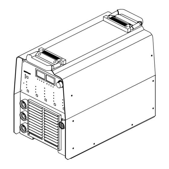
SECTION 13 − PARTS LIST Hardware is common and not available unless listed. Figure 13-1. Main Assembly ST-802 005-H OM-2222 Page 72... - Page 79 Quantity Model Item Dia. Part 230/460 400 CE Mkgs. Description Figure 13-1. Main Assembly ....206 108 HANDLE, rubberized carrying .......
- Page 80 Quantity Model Item Dia. Part Mkgs. Description 230/460 400 CE Figure 13-1. Main Assembly (Continued) ... 197 181 CONNECTOR & SOCKETS 10-pin (LX Models) ....
- Page 81 Hardware is common and not available unless listed. ST-802 006-D Figure 13-2. Windtunnels w/Components Quantity Model Item Dia. Part 230/460 400 CE Mkgs. Description Figure 13-2. Windtunnels w/Components (Figure 13-1 Item 39) ..
- Page 82 Quantity Model Item Dia. Part 230/460 400 CE Mkgs. Description Figure 13-2. Windtunnels w/Components (Figure 13-1 Item 39) (Continued) ....025 248 STAND-OFF, insul .250-20 x 1.250 lg .
- Page 83 Effective January 1, 2006 (Equipment with a serial number preface of “LG” or newer) This limited warranty supersedes all previous Miller warranties and is exclusive with no other Warranty Questions? guarantees or warranties expressed or implied. LIMITED WARRANTY − Subject to the terms and conditions...
-
Page 84: Options And Accessories
Contact the Delivering Carrier to: File a claim for loss or damage during shipment. For assistance in filing or settling claims, contact your distributor and/or equipment manufacturer’s Transportation Department. © PRINTED IN USA 2006 Miller Electric Mfg. Co. 2006−01...
Need help?
Do you have a question about the Maxstar 300 LX and is the answer not in the manual?
Questions and answers