Advertisement
Quick Links
www.ti.com
EVM User's Guide: BQ25750
BQ25750 Evaluation Module
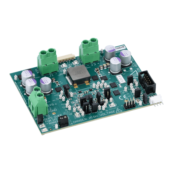
Description
The BQ25750EVM evaluation module (EVM) is a
complete evaluation system for the BQ25750 IC, a
buck-boost battery charge controller with direct power
path control. The BQ25750 has a wide input range of
4.2 V – 70 V, a wide output voltage range of up to 70
V, and bi-directional capabilities.
The BQ25750EVM has a max input and output of 55
V and a max charge current of 10 A.
Get Started
1. Order the EVM on
ti.com
2. Order the
EV2400
to communicate with the EVM
3. Download the BQ25750 BQZ file
4. Download the BQ25750 EVM design files on
ti.com
SLUUCY7 – NOVEMBER 2023
Submit Document Feedback
Features
•
Wide input voltage operating range: 4.2 V – 55 V
•
Wide output operating range: up to 55 V with
CC/CV support for:
– 2 to 13–Cell Li-Ion
– 2 to 14–Cell LiFePO4
•
Synchronous buck-boost DC/DC charge controller
with NFET drivers
– Adjustable switching frequency from 200 kHz to
– Optional synchronization to external clock
– Optional gate driver supply input for optimized
•
Resistor-programmable stand-alone with added
I2C mode
•
Built in MPPT to maximize power from solar panel
arrays
•
Power up from battery (reverse-mode) output 4 V
to 55 V
•
High safety integration
– Adjustable input overvoltage and undervoltage
– Output overvoltage and overcurrent protection
Copyright © 2023 Texas Instruments Incorporated
600 kHz
efficiency
protection
BQ25750 Evaluation Module
Description
1
Advertisement

Related Manuals for Texas Instruments BQ25750


Summary of Contents for Texas Instruments BQ25750
- Page 1 Wide output operating range: up to 55 V with buck-boost battery charge controller with direct power CC/CV support for: path control. The BQ25750 has a wide input range of – 2 to 13–Cell Li-Ion 4.2 V – 70 V, a wide output voltage range of up to 70 –...
-
Page 2: Kit Contents
1 BQ25750 EVM 1.3 Device Information The BQ25750EVM evaluation module (EVM) is an evaluation system for the BQ25750 IC. The BQ25750 IC is a buck-boost battery charge controller with direct power path control. The BQ25750 has a wide input range of 4.2 V –... - Page 3 Evaluation Module Overview 1.4 Texas Instruments High Voltage Evaluation User Safety Guidelines WARNING Always follow TI's set-up and application instructions, including use of all interface components within their recommended electrical rated voltage and power limits. Always use electrical safety precautions to help verify your personal safety and those working around you.
-
Page 4: General Safety Information
1.4.1 General Safety Information The following warnings and cautions are noted for the safety of anyone using or working close to the BQ25750 EVM. Observe all safety precautions. The BQ25750EVM circuit module can become hot during operation due to the dissipation of heat. - Page 5 Evaluation Module Overview CAUTION The default settings of the BQ25750 are not designed for all applications. Set the EVM settings appropriately for test setup before device power up. Set all protections appropriately and limit current for safe operations. CAUTION The board has no fuse installed and relies on the external voltage source current limit for circuit protection.
- Page 6 J6-EXT_DRV Connection for external gate drive J7-Power Connector Connection for VAC and BAT J8-Communication Port Connection for EXT_DRV, /INT, I2C, /PG, and 3.3 V BQ25750 Evaluation Module SLUUCY7 – NOVEMBER 2023 Submit Document Feedback Copyright © 2023 Texas Instruments Incorporated...
-
Page 7: Recommended Operating Conditions
The default EVM input current limit is set to 8 A through the IIN pin. The current-limiting feature can be turned off by setting the EN_IIN_PIN bit to '0', changing the IIN pin resistor, or shorting the IIN pin to PGND through JP11. SLUUCY7 – NOVEMBER 2023 BQ25750 Evaluation Module Submit Document Feedback Copyright © 2023 Texas Instruments Incorporated... -
Page 8: Power Supplies
7. Connect J5 to the EV2400. Connect J5 to the I C PORT 2 on the EV2400. 8. Install the jumpers as indicated in IO and Jumper Descriptions. BQ25750 Evaluation Module SLUUCY7 – NOVEMBER 2023 Submit Document Feedback Copyright © 2023 Texas Instruments Incorporated... - Page 9 V(J1(VAC)) = 40 V ± 0.5 V I(J1(IAC)) = 2.4 A ± 0.5 A V(J3(VBAT)) = 23 V ± 0.5 V I(J3(IBAT)) = 3.9 A ± 0.5 A SLUUCY7 – NOVEMBER 2023 BQ25750 Evaluation Module Submit Document Feedback Copyright © 2023 Texas Instruments Incorporated...
- Page 10 V(J3(VBAT)) = 23 V ± 0.5 V I(J3(IBAT)) = 3.9 A ± 0.5 A Use the following guidelines to test the BQ25750 EVM power path: 1. Disconnect the power supply from J1 (VIN and PGND) and disconnect Load 1 from J3 (VOUT and PGND).
- Page 11 Select Charger_1_00_BQ25750.bqz on the Select a Target Page. c. Click Field View after selecting the target device and then click the Read Register button. SLUUCY7 – NOVEMBER 2023 BQ25750 Evaluation Module Submit Document Feedback Copyright © 2023 Texas Instruments Incorporated...
- Page 12 V(J3(VBAT)) = 23.5 V ± 0.5 V I(J3(IBAT)) = 2 A ± 0.5 A Use the following guidelines to test the BQ25750 EVM power path: 1. Disconnect the power supply from J1 (VIN and PGND) and disconnect Load 1 from J3 (VOUT and PGND).
- Page 13 Avoid physical contact with any part of the board when power is active P GND Output power limited by circuit operating conditions and power stage components Figure 3-1. BQ25750 EVM Schematic SLUUCY7 – NOVEMBER 2023 BQ25750 Evaluation Module Submit Document Feedback...
- Page 14 100pF PGND C516 C517 C518 C519 C506 C507 15uF 15uF 15uF 15uF 15uF 15uF R401 R400 100V 100nF 100k 100k 100V 1µF 100V PGND BQ25750 Evaluation Module SLUUCY7 – NOVEMBER 2023 Submit Document Feedback Copyright © 2023 Texas Instruments Incorporated...
- Page 15 TP 38 TP 39 TP 47 TP 40 HIDRV1 BTST1 HIDRV2 BTST2 STAT1 /INT STAT2 3V3_PULLUP PGND PGND PGND PGND P GND PGND PGND SLUUCY7 – NOVEMBER 2023 BQ25750 Evaluation Module Submit Document Feedback Copyright © 2023 Texas Instruments Incorporated...
- Page 16 Install label in silkscreened box a er final wash. Text shall be 8 pt font. Text shall be per the Label Table in the PDF schema c. Assembly Note For BQ25750 variant, Install JP1, JP4, JP5, JP6, JP9, JP10, pin 1-2 of JP12, JP13, JP14, JP15, and JP16 Assembly Note...
-
Page 17: Pcb Layout
Hardware Design Files 3.2 PCB Layout Figure 3-2. Top Layer and Overlay Figure 3-3. Layer 2 -GND SLUUCY7 – NOVEMBER 2023 BQ25750 Evaluation Module Submit Document Feedback Copyright © 2023 Texas Instruments Incorporated... - Page 18 Hardware Design Files www.ti.com Figure 3-4. Signal Layer 1 Figure 3-5. Signal Layer 2 BQ25750 Evaluation Module SLUUCY7 – NOVEMBER 2023 Submit Document Feedback Copyright © 2023 Texas Instruments Incorporated...
- Page 19 Hardware Design Files Figure 3-6. Layer 5 - GND Figure 3-7. Bottom Layer SLUUCY7 – NOVEMBER 2023 BQ25750 Evaluation Module Submit Document Feedback Copyright © 2023 Texas Instruments Incorporated...
- Page 20 Automotive 3-Pin SOT-23 T/R D2, D3 V1FM10-M3/H Vishay Diode Schottky 1A Surface Mount DO-219AB DO-219AB (SMF) D4, D5, D6 Green 150060VS75000 Wurth Elektronik LED, Green, SMD LED_0603 BQ25750 Evaluation Module SLUUCY7 – NOVEMBER 2023 Submit Document Feedback Copyright © 2023 Texas Instruments Incorporated...
- Page 21 Withstanding Metal Element R3, R8, R9, CRCW06030000Z0EA Vishay Thick Film Resistors - SMD 1/10watt R12, R13, R17, ZEROohm Jumper R20, R23, R68, R69, R100, R160 SLUUCY7 – NOVEMBER 2023 BQ25750 Evaluation Module Submit Document Feedback Copyright © 2023 Texas Instruments Incorporated...
- Page 22 RES, 2.49 k, 1%, 0.1 W, 0603 4.99k CRCW06034K99FKEAC Vishay-Dale RES, 4.99 k, 1%, 0.1 W, 0603 R200, R201 1.8k RC0603JR-071K8L Yageo RES, 1.8 k, 5%, 0.1 W, 0603 BQ25750 Evaluation Module SLUUCY7 – NOVEMBER 2023 Submit Document Feedback Copyright © 2023 Texas Instruments Incorporated...
- Page 23 Standalone/I2C Controlled, 70V, 20A Buck- VQFN36 Boost Multi-Chemistry Battery Charge Controller LT3010EMS8E-PBF Analog Devices Linear Voltage Regulator IC Positive MSOP8 Adjustable 1 Output 50mA 8-MSOP-EP SLUUCY7 – NOVEMBER 2023 BQ25750 Evaluation Module Submit Document Feedback Copyright © 2023 Texas Instruments Incorporated...
- Page 24 STANDARD TERMS FOR EVALUATION MODULES Delivery: TI delivers TI evaluation boards, kits, or modules, including any accompanying demonstration software, components, and/or documentation which may be provided together or separately (collectively, an “EVM” or “EVMs”) to the User (“User”) in accordance with the terms set forth herein.
- Page 25 www.ti.com Regulatory Notices: 3.1 United States 3.1.1 Notice applicable to EVMs not FCC-Approved: FCC NOTICE: This kit is designed to allow product developers to evaluate electronic components, circuitry, or software associated with the kit to determine whether to incorporate such items in a finished product and software developers to write software applications for use with the end product.
- Page 26 www.ti.com Concernant les EVMs avec antennes détachables Conformément à la réglementation d'Industrie Canada, le présent émetteur radio peut fonctionner avec une antenne d'un type et d'un gain maximal (ou inférieur) approuvé pour l'émetteur par Industrie Canada. Dans le but de réduire les risques de brouillage radioélectrique à...
- Page 27 www.ti.com EVM Use Restrictions and Warnings: 4.1 EVMS ARE NOT FOR USE IN FUNCTIONAL SAFETY AND/OR SAFETY CRITICAL EVALUATIONS, INCLUDING BUT NOT LIMITED TO EVALUATIONS OF LIFE SUPPORT APPLICATIONS. 4.2 User must read and apply the user guide and other available documentation provided by TI regarding the EVM prior to handling or using the EVM, including without limitation any warning or restriction notices.
- Page 28 Notwithstanding the foregoing, any judgment may be enforced in any United States or foreign court, and TI may seek injunctive relief in any United States or foreign court. Mailing Address: Texas Instruments, Post Office Box 655303, Dallas, Texas 75265 Copyright © 2023, Texas Instruments Incorporated...
- Page 29 TI products. TI’s provision of these resources does not expand or otherwise alter TI’s applicable warranties or warranty disclaimers for TI products. TI objects to and rejects any additional or different terms you may have proposed. IMPORTANT NOTICE Mailing Address: Texas Instruments, Post Office Box 655303, Dallas, Texas 75265 Copyright © 2023, Texas Instruments Incorporated...
Need help?
Do you have a question about the BQ25750 and is the answer not in the manual?
Questions and answers