Table of Contents
Advertisement
Quick Links
www.ti.com
User's Guide
BQ25180 EVM User's Guide
This user's guide provides detailed testing instructions for the BQ25180 evaluation module (EVM). Also included
are descriptions of the necessary equipment, equipment setup, procedures, the printed-circuit board layouts,
schematics, and the bill of materials (BOM).
Throughout this user's guide, the abbreviation EVM, BQ25180EVM, and the term evaluation module are
synonymous with the BQ25180 evaluation module, unless otherwise noted.
1
Introduction.............................................................................................................................................................................2
1.1 Features.............................................................................................................................................................................
2 EVM Setup...............................................................................................................................................................................
Procedures.................................................................................................................................................................5
4.1 Equipment..........................................................................................................................................................................
4.2 Charge Mode.....................................................................................................................................................................
4.3 Ship Mode..........................................................................................................................................................................
Layouts............................................................................................................................................................................9
6
Schematic..............................................................................................................................................................................10
7 Bill of Materials.....................................................................................................................................................................
8 Revision History...................................................................................................................................................................
Figure 4-1. BQ25180 EVM Connections.....................................................................................................................................
Figure 4-2. TI Charger GUI Device Selection..............................................................................................................................
Figure 4-3. BQ25180EVM Connected.........................................................................................................................................
Start.................................................................................................................................................................7
Figure 4-5. Register Map.............................................................................................................................................................
Figure 4-6. SHIP_RST Register..................................................................................................................................................
Figure 5-1. Top Overlay...............................................................................................................................................................
Figure 5-2. Top Solder.................................................................................................................................................................
Layer...................................................................................................................................................................9
Figure 5-4. Bottom Layer.............................................................................................................................................................
Solder............................................................................................................................................................9
Overlay..........................................................................................................................................................9
Schematic........................................................................................................................................10
Figure 6-2. BQ25180EVM Jumper Connectors.........................................................................................................................
Peripherals.......................................................................................................................................12
Table 2-1. Jumper Descriptions...................................................................................................................................................
Table 3-1. Factory Jumper Settings.............................................................................................................................................
Materials..........................................................................................................................................................13
Trademarks
All trademarks are the property of their respective owners.
SLUUCH5A - AUGUST 2021 - REVISED JANUARY 2022
Submit Document Feedback
ABSTRACT
Table of Contents
Points..........................................................................................................................................4
List of Figures
List of Tables
Conditions.........................................................................................................................3
Copyright © 2022 Texas Instruments Incorporated
Table of Contents
2
2
5
5
8
13
16
5
6
7
8
8
9
9
9
11
2
4
BQ25180 EVM User's Guide
1
Advertisement
Table of Contents

Related Manuals for Texas Instruments BQ25180


Summary of Contents for Texas Instruments BQ25180
-
Page 1: Table Of Contents
BQ25180 EVM User's Guide ABSTRACT This user's guide provides detailed testing instructions for the BQ25180 evaluation module (EVM). Also included are descriptions of the necessary equipment, equipment setup, procedures, the printed-circuit board layouts, schematics, and the bill of materials (BOM). -
Page 2: Introduction
1 Introduction The BQ25180EVM is an evaluation kit for the BQ25180 integrated battery charge management IC. The BQ25180 is an integrated battery charge management IC that integrates the most common functions for wearable devices: linear charger, regulated output, manual reset with timer, and ship mode function. -
Page 3: Table 2-2. Recommended Operating Conditions
Input Current Range (IN to SYS) IBAT Battery Discharge Current (BAT to SYS) Operating Ambient Temperature Range °C Operating Junction Temperature Range °C SLUUCH5A – AUGUST 2021 – REVISED JANUARY 2022 BQ25180 EVM User's Guide Submit Document Feedback Copyright © 2022 Texas Instruments Incorporated... -
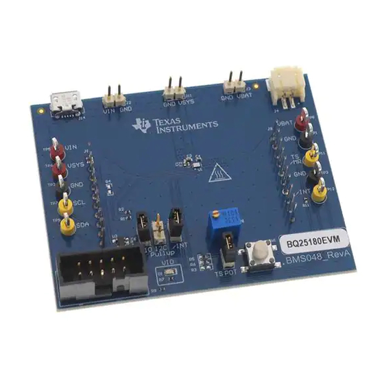
Page 4: Evm Connectors And Test Points
Micro USB connector (optional for VIN) Note Connecting the J7 jumper will enable the VIO LED. This LED will draw 10mA. BQ25180 EVM User's Guide SLUUCH5A – AUGUST 2021 – REVISED JANUARY 2022 Submit Document Feedback Copyright © 2022 Texas Instruments Incorporated... -
Page 5: Testing Procedures
TI Charger GUI from Texas Instruments. 4.2 Charge Mode Connect the equipment as the following: • Power Supply PS#1: VIN of the BQ25180 at 5V • Power supply PS#2: VBAT of the BQ25180 at 3.7V • Scope Channel SC#1: VIN •... -
Page 6: Figure 4-2. Ti Charger Gui Device Selection
If the supplies (VIN and VBAT) are turned off, you will need to restart the TI Charger GUI for correct C transactions to be reflected in the TI Charger GUI Figure 4-2. TI Charger GUI Device Selection BQ25180 EVM User's Guide SLUUCH5A – AUGUST 2021 – REVISED JANUARY 2022 Submit Document Feedback Copyright © 2022 Texas Instruments Incorporated... -
Page 7: Figure 4-3. Bq25180Evm Connected
Select the BQ2518X from the charger selection. Click Quick Start or Register Map. Figure 4-3. BQ25180EVM Connected The Quick Start is shown in Figure 4-4 Figure 4-4. Quick Start SLUUCH5A – AUGUST 2021 – REVISED JANUARY 2022 BQ25180 EVM User's Guide Submit Document Feedback Copyright © 2022 Texas Instruments Incorporated... -
Page 8: Ship Mode
You will know you are in Ship Mode as the voltage on the SYS (SC#2) will fall to 0 V. Figure 4-6. SHIP_RST Register BQ25180 EVM User's Guide SLUUCH5A – AUGUST 2021 – REVISED JANUARY 2022 Submit Document Feedback Copyright © 2022 Texas Instruments Incorporated... -
Page 9: Pcb Layouts
Figure 5-2. Top Solder Figure 5-3. Top Layer Figure 5-4. Bottom Layer Figure 5-5. Bottom Solder Figure 5-6. Bottom Overlay SLUUCH5A – AUGUST 2021 – REVISED JANUARY 2022 BQ25180 EVM User's Guide Submit Document Feedback Copyright © 2022 Texas Instruments Incorporated... -
Page 10: Schematic
/INT TP12 4.7uF 10µF 0.1uF TS/MR TS/MR TP11 BQ25180YBGT BQ2518x Power Path Battery charger IC Figure 6-1. BQ25180EVM Schematic BQ25180 EVM User's Guide SLUUCH5A – AUGUST 2021 – REVISED JANUARY 2022 Submit Document Feedback Copyright © 2022 Texas Instruments Incorporated... -
Page 11: Figure 6-2. Bq25180Evm Jumper Connectors
Texas Instruments and/or its licensors do not SVN Rev: Not in version control Assembly Varia nt: [No Variations] Sheet: ular purpose, or will operate in an imple mentation. Texas Instruments and/or its Drawn By: File : BMS048_RevA_Schematic.SchDoc Size: http://www.ti.com r design imple mentation to confirm the system functionality for your application. -
Page 12: Figure 6-3. Ldo For Other Peripherals
Schematic www.ti.com 4.7uF TPS7A0233PDBVR LDO for IO Figure 6-3. LDO for Other Peripherals BQ25180 EVM User's Guide SLUUCH5A – AUGUST 2021 – REVISED JANUARY 2022 Submit Document Feedback Copyright © 2022 Texas Instruments Incorporated... -
Page 13: Bill Of Materials
W x 0.200" H - 10,000 per roll R1, R2, R11 10.0k RES, 10.0 k, 1%, 0.063 0402 RC0402FR-0710KL Yageo America W, 0402 SLUUCH5A – AUGUST 2021 – REVISED JANUARY 2022 BQ25180 EVM User's Guide Submit Document Feedback Copyright © 2022 Texas Instruments Incorporated... - Page 14 Texas Instruments Ultralow IQ Low-Dropout Regulator, DBV0005A (SOT-23-5) FID1, FID2, FID3 Fiducial mark. There is nothing to buy or mount. BQ25180 EVM User's Guide SLUUCH5A – AUGUST 2021 – REVISED JANUARY 2022 Submit Document Feedback Copyright © 2022 Texas Instruments Incorporated...
- Page 15 Yageo America W, AEC-Q200 Grade 0, 0402 RES, 0, 5%, 0.1 W, AEC- 0402 ERJ-2GE0R00X Panasonic Q200 Grade 0, 0402 SLUUCH5A – AUGUST 2021 – REVISED JANUARY 2022 BQ25180 EVM User's Guide Submit Document Feedback Copyright © 2022 Texas Instruments Incorporated...
-
Page 16: Revision History
Changes from Revision * (August 2021) to Revision A (January 2022) Page • Production release of EVM user's guide......................1 BQ25180 EVM User's Guide SLUUCH5A – AUGUST 2021 – REVISED JANUARY 2022 Submit Document Feedback Copyright © 2022 Texas Instruments Incorporated... - Page 17 STANDARD TERMS FOR EVALUATION MODULES Delivery: TI delivers TI evaluation boards, kits, or modules, including any accompanying demonstration software, components, and/or documentation which may be provided together or separately (collectively, an “EVM” or “EVMs”) to the User (“User”) in accordance with the terms set forth herein.
- Page 18 www.ti.com Regulatory Notices: 3.1 United States 3.1.1 Notice applicable to EVMs not FCC-Approved: FCC NOTICE: This kit is designed to allow product developers to evaluate electronic components, circuitry, or software associated with the kit to determine whether to incorporate such items in a finished product and software developers to write software applications for use with the end product.
- Page 19 www.ti.com Concernant les EVMs avec antennes détachables Conformément à la réglementation d'Industrie Canada, le présent émetteur radio peut fonctionner avec une antenne d'un type et d'un gain maximal (ou inférieur) approuvé pour l'émetteur par Industrie Canada. Dans le but de réduire les risques de brouillage radioélectrique à...
- Page 20 www.ti.com EVM Use Restrictions and Warnings: 4.1 EVMS ARE NOT FOR USE IN FUNCTIONAL SAFETY AND/OR SAFETY CRITICAL EVALUATIONS, INCLUDING BUT NOT LIMITED TO EVALUATIONS OF LIFE SUPPORT APPLICATIONS. 4.2 User must read and apply the user guide and other available documentation provided by TI regarding the EVM prior to handling or using the EVM, including without limitation any warning or restriction notices.
- Page 21 Notwithstanding the foregoing, any judgment may be enforced in any United States or foreign court, and TI may seek injunctive relief in any United States or foreign court. Mailing Address: Texas Instruments, Post Office Box 655303, Dallas, Texas 75265 Copyright © 2019, Texas Instruments Incorporated...
- Page 22 TI products. TI’s provision of these resources does not expand or otherwise alter TI’s applicable warranties or warranty disclaimers for TI products. TI objects to and rejects any additional or different terms you may have proposed. IMPORTANT NOTICE Mailing Address: Texas Instruments, Post Office Box 655303, Dallas, Texas 75265 Copyright © 2022, Texas Instruments Incorporated...
Need help?
Do you have a question about the BQ25180 and is the answer not in the manual?
Questions and answers