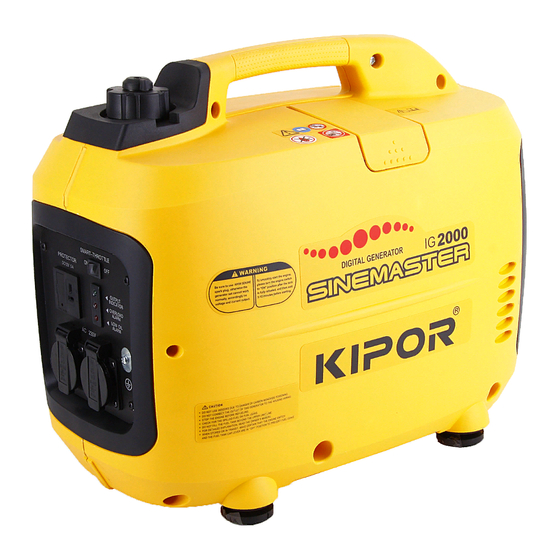
Kipor IG2000 Manual
Hide thumbs
Also See for IG2000:
- Shop manual (90 pages) ,
- Operation manual (50 pages) ,
- Operation manual (54 pages)
Table of Contents
Advertisement
Advertisement
Table of Contents

Related Manuals for Kipor IG2000


Summary of Contents for Kipor IG2000
- Page 2 All information, illustrations, directions and specifications included in this publication are based on the latest product information available at the time of approval for printing. KIPOR POWER CO., LTD, reserves the right to make changes without incurring any obligation. No...
-
Page 3: Table Of Contents
CONTENTS 1. SPECIFICATIONS 1.1 SPECIFICATIONS 1.2 CHARACTERISTICS 1.3 PERFORMANCE CURVES 1.4 DIMENSIONAL DRAWINGS 1.5 WIRING DIAGRAM SERVICE INFORMATIONS 2.1 THE IMPORTANTANCE OF PROPER SERVICE 2.2 IMPORTANT SAFETY PRECAUTIONS 2.3 SERVICE RULES 2.4 SERIES NUMBER LOCATION 2.5 MAINTENANCE STANDARDS 2.6 TORQUE VALUES 2.7 TROUBLESHOOTING 3. - Page 4 7.5 GUIDE PLATE 7.6 INSPECTION 8. RECOIL STARTER/FAN SHIELD/IGNITION COIL 8.1 DISASSEMBLY, ASSEMBLY 8.2 RECOIL STARTER 8.3 INSPECTION 9. GENERATOR, TRIGGER 9.1 GENERATOR 9.2 CHECK 9.3 REGULATE 10. CYLINDER COVER/ROCKER ARM- 10.1 DISASSEMBLY, ASSEMBLY 10.2 INSPECTION 11. CRANKCASE COVER/CAM TIMING DRIVING CHAIN WHEEL 11.1 DISASSEMBLY 11.2 CRANKCASE COVER 11.3 ROLLER CHAIN...
-
Page 6: Specifications
1. SPECIFICATIONS 1.1 SPECIFICATIONS Dimensions and weights Model IG2000/IG2000p/CG2000 IG2000s/CG2000s Overall Length 520mm 665mm Overall Width 300mm 300mm Overall Height 425mm 425mm Net Weight 22Kg 24Kg Engine Model KG158 Type 4-stroke,OVC, single cylinder, Gasoline engine Displacement 105.6ml Bore x stroke... -
Page 7: Characteristics
1.2 CHARACTERISTICS Model IG2000/IG2000s/IG2000p/CG2000/CG2000s Maximum output AC 2.0KVA Rated output AC 1.6KVA Rated output DC 100W Rated frequency 50Hz 60HZ 60HZ Rated voltage AC 230V 120V 240V Rated voltage DC Rated current AC 7.0A 13.3A 6.7A Rated current DC 8.3A Power factor 1.0cosφ... -
Page 8: Performance Curves
1.3 PERFORMANCE CURVES The curves show performance of the generator under average condition. Performance may vary to some degree depending on ambient temperature and humidity. The output voltage will be higher than usual when the generator is still cold, immediately after the engine starts. - Page 9 1.4 DIMENSIONAL DRAWING Unit: mm a. IG2000\IG2000p/CG2000 b. IG2000s/CG2000s...
-
Page 10: Wiring Diagram
1.5 WIRING DIAGRAM a. IG2000/IG2000s b: IG2000p c. CG2000/CG2000s... -
Page 11: Service Informations
Keep all cigarettes, sparks, and flames away from all fuel-related parts. 2.3 Service rules 1. Use genuine KIPOR or KIPOR-recommended parts and lubricants or their equivalents. Parts that do not meet Kipor’s design specifications may damage the engine. 2. Use the special tools designed for the product. - Page 12 6. After reassembly, check all parts for proper installation and operation. 7. Many screws used in this machine are self-tapping. Be aware that cross-threading or over tightening these screws will strip the threads and ruin the hole. 8. Use only metric tools when servicing this engine. Metric bolts, nuts and screws are not interchangeable with no metric fasteners.
-
Page 13: Maintenance Standards
2.5 Maintenance standards Engine Part Item Standard(mm) Service limit Maximum speed without load 4300±100rpm — Engine Compress force 0.45Mpa/800rpm — Cylinder Sleeve I.D. 58.000-58.020 58.105 Skirt O.D 57.960-57.980 57.85 Piston Pin bore I.D. 13.002-13.008 13.05 Piston pin 12.994-13.000 12.95 Height h 0.97-0.99 0.87 Ring side clearance... -
Page 14: Torque Values
Motor Standard(Ω) IG series CG series Part Item Type 230V/240 230V/24 120V Ignition winding Resistance Green-Yellow/Green 0.40-0.55 Outer charging Resistance Blue--Blue 0.12-0.15 winding White-White (IG) Sub winding Resistance 0.15-0.30 White-White (CG) Black—Black-Black (IG) 1.35-1 0.18-0. 0.65-0. Main winding Resistance Black-Yellow/Black-Gr 5.0-5.5 een/Black-Red (CG) - Page 15 Throttle opening fault Set in fully close or half close position Carburetor faulty Adjust and/or disassemble and clean Engine speed Throttle control motor (stepping Inspect and replace does not motor) faulty stabilize, too Inverter unit faulty Inspect and replace high or too low Valve clearance misadjusted Readjust b.
- Page 16 Cylinder compression 0.45Mpa/800rpm...
- Page 17 C. Ignition system ■ Fill in oil to the demanded level. ■ Use the genuine spark plug A7RTC. ■ Spark plug inspection 1. Disassemble spark plug 2. Install spark plug onto spark plug cap. 3. Set the oil switch to the “ON” position. Ground the negative (—) electrode (i.e. threaded part) of the spark plug against the shroud and pull the recoil starter rope to check the spark plug.
- Page 18 Measure the spark plug gap and perform the spark plug test. Standard clearance: 0.6—0.8mm No spark Good spark Perform the spark test again using a Replace the spark plug new spark plug No spark Good spark Remove the control panel. Perform Replace the ignitor the spark test using a new ignitor.
- Page 19 e. Engine stops running (Throttle is at the correct position) Oil alarm Check the oil level and oil alarm Fill in oil and restart the engine Sufficient oil Reset the alarm connection wire, disconnect No fuel Fill in fuel and restart the engine ignitor plug, and check the continuity between the plug orange wire and ground.
- Page 20 f. Engine speed can’t increase or instable (choke is at the correct position) Blocked Check the air filter element for blockage Clear the air filter element No blocked Abnormal Check the valve clearance Readjust the valve clearance Normal Remove the spark plug and check the Abnormal Clear electrode, adjust clearance electrode clearance for carbon deposit...
- Page 21 2. Smart system doesn’t work with zero load, engine speed doesn’t increase with Smart system on and load connected. Perform generator Abnormal Check the AC output troubleshooting following instruction of “No or low AC output” Normal Abnormal Check the throttle control motor Replace the throttle control motor Normal Abnormal...
- Page 22 Measure voltage IG series CG series Phase wire color: Phase wire color: Black-Black-Black Yellow-Green-Red Model Sub winding color: Neutral wire color: Black White-White Sub winding color: Black-Green Item 120V 230V\240V 120V 230V\240V Voltage >30V >60V >15V >30V between phase wires Sub winding >1V voltage...
- Page 23 ■ The parallel cable is only used for 2 generators with the same model. It can’t be used for 3 or more than 3 generators. ■ Only KIPOR parallel output cable and communication wire is allowed to use, never try other cables. Use the receptacle output of parallel cable, don’t use the receptacle of control panel.
- Page 24 ■ Don’t output current after stopping one generator when the parallel cable is still connected. ■ Do disconnect the parallel output cable and parallel communication wire if operate the generator separately. Perform single generator Check whether the two generators could Abnormal troubleshooting work well separately.
-
Page 25: Engine Oil
(1) For commercial use, operation hours are determined by proper maintenance. (2) Service more frequently when operating in dusty areas, every 10 hrs or every day. (3) Service by KIPOR authorized agency, unless correct tools or professional specialist is available. Do service according to the manual. - Page 26 3. If the oil level is low, add to the edge of the oil filler port. ■ Replace the engine oil 1. Disassemble the oil dipstick and oil drain bolt, drain out dirty oil. 2. Fix the oil drain bolt tightly. 3.
- Page 27 3.3 Checking for the low oil alarm 1. Disconnect oil alarm connector when the engine is still running, connect the two plugs, be sure that oil alarm lights and engine stops. 2. Stop engine, disconnect oil alarm connector, check the connector conduction, no conduct is normal. 3.
-
Page 28: Air Cleaner
3.4 Air cleaner Inspection/Cleaning: 1) Loosen the cover screw and remove the maintenance cover. 2) Disengage the locking tab by pushing it, and remove the air cleaner cover. 3) Remove the element from the air cleaner case. 4) Clean the element in warm soapy water, rinse and allow to dry thoroughly, or clean with a high flash point solvent and allow to dry. -
Page 29: Spark Plug
Caution ■ A dirty air cleaner will restrict air flow to the carburetor, reducing engine performance. If the engine is operated in dusty areas, clean the air cleaner more often than specified in the Maintenance Schedule. ■ Never run the engine in case there is no element or the filter is damaged, as it will do great harm to the engine. -
Page 30: Valve Clearance
3.6 Valve clearance Caution ■ Valve clearance inspection and adjustment must be performed with the engine cold. Inspection/Adjustment: 1) Remove the following parts: ―Front cover, control panel ―Rear cover ―Right/left side covers ―Fuel tank ―Inverter unit, engine bed ―Recoil starter, fan cover ―Inlet/Exhaust side baffler 2) Remove the four tighten bolts and disassemble the cylinder cover. - Page 31 Caution ■ If the inlet valve is on, turn the rotor again to align the timing line with the cylinder head seal, and both the inlet and exhaust valve should be closed. 4) Insert a feeler gauge between the rocker arm and the valve and measure the valve clearance. 0.10±0.02mm Valve clearance 0.15±0.02mm...
- Page 32 3.7 Fuel tank/Fuel filter Caution ■ Gasoline is highly flammable and explosive. You can be burned or seriously injured when handling fuel. Keep heat, sparks, and flame away. Wipe up spills immediately. Cleaning: 1) Drain the fuel from the tank and carburetor, and then remove the following parts. ―Rear cover ―Front cover and control panel ―Right/Left side cover...
- Page 33 2) Check the fuel tube for deterioration, cracks and gasoline leakage. If there is any abnormality in the fuel tube, replace the tube. 3) Check the diaphragm tube for deterioration, crack and oil leakage. If there is any abnormality in the diaphragm tube, replace the tube.
-
Page 34: Muffler
4. Muffler Caution ■ Muffler removal/installation must be performed with the engine cold. ● Disassembly/Reassembly... -
Page 35: Air Filter/Carburetor
5. Air filter/Carburetor Caution ■ Loosen the drain oil bolt and drain out fuel before disassembly. ■ Keep heat, flame and sparks away. 5.1 Disassembly/Installation of Air filter 5.2 Disassembly/Installation of Carburetor... - Page 36 ● Disassembly/Installation of Stepping motor...
- Page 37 ● Disassembly/Installation of Carburetor...
-
Page 38: Inspection
5.3 Inspection ● Float height Place the carburetor as the picture shows, measure the float height between float and carburetor block. Height 12mm Replace the float if the float height is not the right size. ● Stepping motor Measure the resistance of stepping motor lead-out wire. Between 1and 3:45~55Ω... -
Page 39: Control Panel
6. Control panel 6.1 Removal/Installation... -
Page 40: Inspection
IG2000/IG2000s IG2000p CG2000/CG2000s 6.2 Inspection a. Control panel ● AC receptacle Check the electrode contact disk inside receptacle, if it is burnt or the color changes, replace for it. ● DC receptacle Connect both terminals of the receptacle with a jumper wire to short. There must be continuity between the lead wire terminals with the circuit protector ON. - Page 41 ● Engine switch Check the continuity of connector, there should be continuity if presses down the micro switch, otherwise, disconnect the switch. ● Aero receptacle (parallel I/O communication port) Check the continuity between connector and aero receptacle, there should be continuity between the two terminals with the same serial number.
- Page 42 ● Aero plug (Parallel I/O communication data wire) Check the continuity of aero plugs, there should be continuity between two plugs with the same serial numbers. ● Parallel output receptacle Check the continuity between the two terminals of parallel output receptacle.
- Page 43 ● Parallel output cable 1. Check the AC receptacle output terminal, there should be no continuity between two terminals. 2. Connect the AC receptacle output terminal with one lead, check the parallel plug; there should be continuity among the four plugs. 3.
-
Page 44: Lamp Chimney
7. Lamp chimney/ Housing case/ Fuel tank/ Baffler/ Inverter unit 7.1 Disassembly and installation of lamp chimney Caution ■ Stop the engine and cool the lamp chimney completely before disassembly. - Page 45 7.2 Disassembly and installation of housing case...
- Page 46 ● Left housing case...
-
Page 47: Fuel Tank
7.3 Fuel tank Caution ■ Gasoline is highly flammable and explosive. You can be burned or seriously injured when handing fuel. Keep heat, sparks, and flame away. Wipe up spills immediately. Loosen the drain screw to drain the carburetor thoroughly before removal. -
Page 48: Fan Shield/Engine Fixed Plate
7.4 Fan shield/Engine fixed plate 7.5 Guide Plate 7.6 Inspection (1) Aluminum shell resistor (CG series) Measure the resistance of aluminum shell resistor. Measuring error is ±5%. Model 120V 230V\240V Resistance 5Ω\50W 10Ω\50W \consumption power (2) Capacitor (CG series) Measure the capacitance. Measuring error is ±5%. Model 120V 230V\240V... -
Page 50: Disassembly, Assembly
8. Recoil starter/ Air conduct cover/ Ignition coil 8.1 Disassembly/Reassembly... - Page 51 8.2 Installation of recoil starter (1) Set the spring into the starter reel, and hang the spring outer hook inside the reel groove. (2) Smear lubrication grease on the starter outer shell claw, install the starter reel. Revolve the reel anticlockwise to hang the spring inner hook on the starter outer shell claw.
-
Page 52: Inspection
(4) Pull out rope thrum from starter outer shell hole completely, pass it through the handle and make a “8” knot, then turn off handle cover. Loosen the reel to rebound the spring, take care not to allow the reel pop out. - Page 53 ● Attach one lead of the tester to each terminal of primary coil plugs of ignition coil and the other lead to the spark plug cap,then measure the secondary resistance of the ignition coil. Secondary resistance 15—21kΩ (2) Rectifier Measure the on or off (positive pressure fall) of rectifier with control potentiometer , the measurement should accord with the standard as shown in the chart.
-
Page 54: Generator, Trigger
9. Generator/ Trigger 9.1 Generator Disassembly/Reassembly 9.2 Inspection (1) Ignition winding Measure the resistance between the green terminal and yellow/green terminal. Resistance 0.40-0.55Ω (2) Outer charging winding Measure the resistance between the two blue terminals. Resistance 0.12-0.15Ω (3) Sub winding Measure the resistance between the two sub winding terminals. - Page 55 1.35~1.75 5.0~5.5 0.18~0.21 0.65~0.90 (5) Trigger Attach the two testers in the trigger, and measure its resistance. Trigger resistance 80-130Ω...
- Page 56 9.3 Adjustment Adjust the clearance between trigger and the projection part of rotor. Trigger clearance 0.50-0.75mm Insert a feeler gauge between the trigger and the projection part of the rotor; loosen the trigger fixed plate bolt to adjust the clearance slightly. Never move the plastic part of trigger, to avoid it separates from the fixed plate and damages the trigger.
-
Page 57: Cylinder Cover/Rocker Arm
10. Cylinder cover/ Rocker arm 10.1 Disassembly/ Reassembly... -
Page 58: Inspection
10.2 Inspection ● Rocker arm outer diameter Standard(mm) Service limit(mm) 5.972-5.980 5.965 ● Rocker arm inner diameter of inlet/exhaust valve Standard(mm) Service limit(mm) 6.000-6.012 6.037 ● Inner diameter of rocker arm bearing Standard(mm) Service limit(mm) 6.000-6.012 6.037... -
Page 59: Disassembly
11. Crankcase cover/ Cam timing drive chain 11.1 Disassembly 11.2 Crankcase cover... -
Page 60: Roller Chain
11.3 Reassembly of roller chain 1. Install the crankshaft, piston and connection rod assembly on the cylinder block. 2. Revolve the crankshaft; align the timing mark of crankshaft timing shaft with the timing mark of crankcase. (Step 1) 3. Install the roller chain on the cam timing drive chain, level the timing mark upward. (Step 2) 4. - Page 61 11.4 Assembly of chain support plate/ pressure plate ● Chain support plate 1. Put the upper groove of chain support plate into block; press the other end to seize the support plate fully. 2. Insert the location pin into cylinder block location hole and align them, set the support plate and clip block into cylinder block.
-
Page 62: Crankcase Cover
11.5 Assembly of crankcase cover 1. Clear the remaining seal gum on the cylinder block and crankcase cover with cloth. 2. Smear seal gum on the cylinder block sealing face, as picture shows. 3. Reassemble the crankcase cover in the opposite direction of disassembly. Caution Install the crankcase cover on the cylinder block 3 minutes after smearing. -
Page 63: Inspection
4. Tighten the crankcase cover bolt slowly, screw to the prescribed torque. 5. Wait for 20 minutes after installation, never refill in oil or start the engine during these 20 minutes. 11.6 Inspection ● Inspection of oil alarm (1) Stand the oil alarm, check the oil alarm output wire and copper earth wire, there should be no continuity. - Page 64 ● Cam inner diameter Standard(mm) Service limit(mm) 9.000-9.015 9.035 ● Camshaft outer diameter Standard(mm) Service limit(mm) 8.966-8.975 8.920 ● Decompression block Check the return spring for damage and weary, make sure the decompression block could perform well.
-
Page 65: Crankshaft/Piston
12. Crankshaft/ Piston 12.1 Disassembly/ Reassembly... -
Page 66: Piston
12.2 Piston Assembly of piston ring Caution ● Set the manufactory label upwards. ● Pay attention not to mix the location of the 1 ring and 2 ring. ● Check the piston ring for flexibility after installation. ● Stagger each piston ring opening apart piston pin for 120°. -
Page 67: Inspection
12.3 Inspection ● Free length of valve spring Standard(mm) Service limit(mm) 26.4 24.9 ● Valve seat width Standard(mm) Service limit(mm) ● Valve rod outer diameter Standard(mm) Service limit(mm) Inlet valve 3.965-3.980 3.90 Exhaust valve 3.955-3.970 3.90... - Page 68 ● Valve guide pipe inner diameter Standard(mm) Service limit(mm) Inlet/Exhaust valve 4.000-4.030 4.060 ● Clearance between valve rod and valve guide pipe Standard(mm) Service limit(mm) Inlet valve 0.020-0.065 0.10 Exhaust valve 0.030-0.075 0.12 ● Cylinder inner diameter Standard(mm) Service limit(mm) 58.000-58.020 58.105...
- Page 69 ● Piston skirt outer diameter Standard(mm) Service limit(mm) 57.960-57.980 57.850 10mm ● Clearance between piston and cylinder Standard(mm) Service limit(mm) 0.020-0.042 0.120 ● Side clearance of piston ring Standard(mm) Service limit(mm) 0.02-0.06 0.15 ● Piston ring end clearance Locate the piston ring into cylinder with piston top, and measure the piston end clearance. Standard(mm) Service limit(mm) 0.15-0.25...
- Page 70 ● Piston ring height Standard(mm) Service limit(mm) The 1 ring 0.97-0.99 0.87 The 2 ring 1.17-1.19 1.107 ● Piston pin outer diameter Standard(mm) Service limit(mm) 12.994-13.000 12.950 ● Piston pin hole inner diameter Standard(mm) Service limit(mm) 13.002-13.008 13.050...
- Page 71 ● Clearance between piston pin and piston pin hole Standard(mm) Service limit(mm) 0.002-0.014 0.080 ● Connection rod small end inner diameter Standard(mm) Service limit(mm) 13.006-13.017 13.080 ● Connection rod big end inner diameter Standard(mm) Service limit(mm) 24.020-24.033 24.090 ● Crankshaft neck outer diameter Standard(mm) Service limit(mm) 23.967-23.980...
- Page 73 ● Connection rod big end side clearance Standard(mm) Service limit(mm) 0.1-.0.4 ● Oil film clearance of connection rod big end (1) Wipe off the oil on the surface of crankshaft neck. (2) Set the plastic wire feeler at the crankshaft neck and install the connection rod. Tighten the bolt to the prescribed torque, pay attention that don’t revolve the crankshaft.
- Page 74 ● Bearing vibration Clear the bearing and dry it, check the clearance between crankshaft journal and connecting rod big end by revolving bearing by hands. Replace for a new bearing if there is abnormal noise or vibration.
Need help?
Do you have a question about the IG2000 and is the answer not in the manual?
Questions and answers