Table of Contents
Advertisement
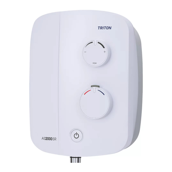
AS2000 SR
Thermostatic
Power Shower
Installation
and Operating
Instructions
I
:
nstallers
please note these
InstructIons are to be left
wIth the user
IMPORTANT SAFETY ADVICE
•
The shower unit MUST BE switched off at the isolating switch when
not in use. This is a safety procedure recommended for all electrical
appliances.
•
The showerhead and hose supplied with this product are a safety
critical part of your shower. Failure to use genuine Triton parts may
cause injury and invalidate your guarantee.
2181606C - September 2019
Advertisement
Table of Contents

Related Manuals for Triton AS2000 SR


Summary of Contents for Triton AS2000 SR
- Page 1 This is a safety procedure recommended for all electrical appliances. • The showerhead and hose supplied with this product are a safety critical part of your shower. Failure to use genuine Triton parts may cause injury and invalidate your guarantee. 2181606C - September 2019...
- Page 2 Power Shower INTRODUCTION - PLEASE READ PLEASE READ THIS IMPORTANT SAFETY INFORMATION Products manufactured by Triton are safe and without risk provided they are installed, used and maintained in good working order in accordance with our instructions and recommendations. ARNING: DO NOT operate shower if frozen, or suspected of being frozen.
- Page 3 IMPORTANT - PLEASE READ THESE Power Shower GENERAL GUIDANCE NOTES BEFORE PROCEEDING GENERAL 2.10 A dedicated cold water supply must be taken directly from the cold water cistern to the Isolate the electrical and water supplies before shower. This draw-off must be on the opposite removing the cover.
-
Page 4: Table Of Contents
SPARE PARTS ......................22 GUARANTEE, SERVICE POLICY, ETC............REAR COVER To check the product suitability for commercial and multiple installations, please contact Triton’s specification advisory service before installation. Please see back of book for contact information. Find our step-by-step installation video for this product on our YouTube... -
Page 5: Specifications
Power Shower IMPORTANT Maximum static inlet pressures 100 Kpa (1 bar) or 10m (supplies must be The shower installation must be carried gravity fed at nominally equal pressures). out by a suitably competent person and in sequence of this instruction book. Minimum static inlet pressure Please read through the whole of this 0.75 Kpa (0.0075 bar) or 75mm (required to... -
Page 6: Main Components
Power Shower Fig.1 MAIN COMPONENTS 1. Cover screw fixing 7. PCB / power supply 2. Motor retaining bracket 8. Setting ring 3. Wall fixing holes 9. Temperature control valve 4. Pipe inlets – swing 10. Solenoid outlet (contains single check valves) 11. -
Page 7: Water And Cable Entry Points
Power Shower Fig.2 Swivel water inlet feature for top or bottom connection Entry Points Key: Dimensions: H: 292mm H & C Water Entry Points Rear Entry W: 219mm Cable D: 115mm Entry Points Rear Entry... -
Page 8: Site Requirements & Recommended Installation
Power Shower Fig.3a - Recommended Installation (Diagrammatic view – not to scale) Ring main Mains supply 25mm min Isolating valve Dedicated cold supply Isolating spur Cold water cistern (3A fused) outside bathroom 75mm Vent pipe tee Isolating valves Isolating valve Hot supply Alternative connection... -
Page 9: General Installation Notes
Power Shower SITE REQUIREMENTS Under no circumstances should this product be connected to mains cold or hot water Water supplies. Failure to comply will invalidate the The installation must be in accordance with guarantee. Water Regulations/Bylaws and BS-EN 806. GENERAL INSTALLATION NOTES For correct operation of this shower unit, both hot and cold water supplies to the appliance 1. -
Page 10: Siting Of The Shower
Power Shower SITING OF THE SHOWER Fig.5 Ceiling WARNING! Space for cover screw access The shower must not be positioned where it will be subject to freezing conditions. IMPORTANT: The unit must be mounted onto Height of sprayhead the finished wall. NEVER tile up to the unit. and shower to suit user’s Refer to fig.5 for correct siting of the shower. -
Page 11: Plumbing Connections
Power Shower PLUMBING CONNECTIONS Fig.8 Plumbing to be carried out before wiring cover Note: The outlet of the shower must not be connected to anything other than the hose and showerhead supplied. 122mm When connecting pipework avoid using tight 90° elbows. Swept or formed bends will give optimum performance. -
Page 12: Fitting The Shower To The Wall
Power Shower The pipe inlets are marked for hot and cold Fig.10 connections – left-hand side for hot inlet on bottom entry (fig.10) and right-hand side for hot inlet on top or rear entry (fig.11). IMPORTANT: The fittings on the inlets are the push-in type. - Page 13 Power Shower Using the backplate as template, mark the Fig.14 positions for the four wall fixing holes (fig.14). Using the pipe removal tool supplied, push back and hold the collets from the pipework to disengage the pipework from the inlets (fig.15). Remove the unit from the wall.
-
Page 14: Electrical Connections
IEE regulations. In most cases 0.75 mm² twin cable If replacing an existing Triton Power Shower NEUTRAL CONNECTION then the floating earth can still be terminated at (Blue or Black Wire) the product terminal block. -
Page 15: Commissioning
Power Shower COMMISSIONING WARNING! BEFORE NORMAL OPERATION Commissioning ON OF THE SHOWER, IT IS ESSENTIAL THAT (switch in UP position) THE COMMISSIONING AND SET UP Pump will not operate PROCEDURE ARE CORRECTLY COMPLETED. FAILURE TO DO SO COULD CAUSE THE PUMP TO RUN DRY WITHOUT WATER AND INVALIDATE THE GUARANTEE. - Page 16 Power Shower In order to dispel air and to prime both supplies to the shower unit, turn the temperature control Fig.21 several times within its rotational limits. Note: The temperature control is fitted with 3 O’clock a maximum temperature stop, pressing the postion override is required to achieve fully hot position.
-
Page 17: Temperature Control Set Up
Power Shower TEMPERATURE CONTROL SET UP Fig.24 On the temperature valve you will see a mark on the brass valve spindle when positioned at 3 O'clock (fig.24), this is the factory setting. Important As a safety feature the shower has a built-in maximum temperature stop to prevent accidental rotation to higher temperatures. -
Page 18: Operating The Shower
Power Shower OPERATING THE SHOWER Fig.27 Make sure all plumbing and electrical supplies are connected and switched on. To start the shower, press the start/stop button (fig.27). Adjust the flow control (fig.28) until the flow rate is satisfactory. For maximum flow, turn the flow control fully clockwise. -
Page 19: Cleaning The Filters
Power Shower INSTRUCTIONS FOR INSTALLERS AND SERVICE ENGINEERS ONLY CLEANING THE FILTERS Fig.30 WARNING! Switch off the electricity supply and turn off both hot and cold water supplies to the unit before proceeding further. To remove the cover, first remove the screw trim from the temperature control knob and then remove the retaining screw. -
Page 20: Fault Finding
Any maintenance or repair to the shower must be carried out by a suitably competent person. In the unlikely event of a fault occurring please contact Triton Customer service. DO NOT remove the shower from the installation. Symptom... - Page 21 Power Shower FAULT FINDING Symptom Cause Action/Cure 4 Water does not 4.1 Water supplies cut off. 4.1.1 Check water elsewhere in house and if necessary contact the local Water Company. flow or is reduced. 4.2.1 Switch off shower and contact Customer 4.2 Shower blocked or air in the system.
-
Page 22: Spare Parts
Please have your model name available. WEEE Directive – Policy Statement As a producer and a supplier of electric showers, Triton Showers is committed to the protection of the environment via our own environmental policy and the compliance with the WEEE directive. - Page 23 Power Shower...
- Page 24 Trade Installer Hotline: 024 7637 8344 Nuneaton www.tritonshowers.co.uk Warwickshire, CV11 4NR E-mail: serviceenquiries@tritonshowers.co.uk E-mail: technical@tritonshowers.co.uk Triton is a division of Norcros Group (Holdings) Limited Triton reserve the right to change product specifi cation without prior notice. E&OE. © TRITON SHOWERS 2019...
Need help?
Do you have a question about the AS2000 SR and is the answer not in the manual?
Questions and answers