Advertisement
Table of Contents
- 1 Table of Contents
- 2 Machine Parameters
- 3 Machine Component Diagrams
- 4 Packing List
- 5 Machine Setup & Installation
- 6 Display Screen Operation Introduction
- 7 Auto-Leveling Procedure
- 8 Model (Operation)Testing
- 9 Resume Printing Function
- 10 Software Installation
- 11 LAN (Network)Printing
- 12 Mainboard Circuit Wiring Diagram
- Download this manual
Advertisement
Table of Contents

Related Manuals for Elegoo NEPTUNE 4 PLUS


Summary of Contents for Elegoo NEPTUNE 4 PLUS
- Page 1 User Manual for NEPTUNE 4 PLUS 3D Printer Pictures are only for illustration purposes. Actual production products may vary from images V1.6...
- Page 2 For any questions or issues not covered in this manual, please contact us directly via our customer support email address: 3dp@elegoo.com. The ELEGOO team is always ready to provide you with quality service. To provide you with the best product experience, in addition to this manual, you can find supplemental information for the operation of your new printer via: 1.
- Page 3 NOTES 1. Do not place the printer in vibrating or other unstable environments, as the shaking of the machine will affect the print quality. 2. Do not touch the nozzle and heated bed when the printer is working to prevent high-temperature burn and personal injury. 3.
- Page 4 Troubleshooting Guide A stepper motor of the X/Y/Z axis is not moving or making a noise when “zeroed” ① The stepper motor cable could be loose. Please recheck the wiring connection. ② The corresponding limit switch may not be triggering properly, please check whether there is any interference in the movement of the corresponding shafts and ensure the limit switch wiring is not loose.
-
Page 5: Table Of Contents
Contents Machine Parameters ------------------------------------------------- Machine Component Diagrams ----------------------------------- Packing List ---------------------------------------------------------- Machine Setup & Installation -------------------------------------- Display Screen Operation Introduction ------------------------ Auto-Leveling Procedure -------------------------------------------- Model (Operation)Testing ------------------------------------------- Resume Printing Function --------------------------------------- Software Installation -------------------------------------------------- LAN (Network)Printing --------------------------------------------- Mainboard Circuit Wiring Diagram -------------------------------... -
Page 6: Machine Parameters
Machine Parameters Printer Specifications Software Specifications Printer Type: FDM(Fused Deposition Modeling) Slicer Software: Cura Maximum Build Volume: 320X320X385(mm³) Input File Format: STL, OBJ Print Precision: ±0.1mm Output File Format: G-code Nozzle Diameter: 0.4mm Interface: USB Drive, LAN (Network), WIFI Print Speed: 30~500mm/s Regular printing speed: 250mm/s... -
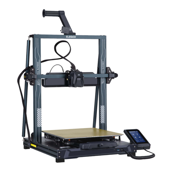
Page 7: Machine Component Diagrams
Machine Component Diagrams Filament Spool Holder Filament Spool Holder Detector/Filament Detection Sensor Support Strut Z-Axis Rod X-Axis Belt X-Axis Stepper Nozzle(Hotend) The Rear Tensioner Motor Assembly Unit Cooling Fan Coupling Build Platform LAN(Network) Type-C Interface Touch screen Port Interface Z-Axis Stepper Y-Axis WIFI Signal Receiver Motor... -
Page 8: Packing List
Fasteners (HM5*45)4pcs (PM4*50)4pcs (PM4*20)5pcs (PM4*18)2pcs (PM3*14) 3pcs Base Unit Gantry Frame Unit (PM4*8)3pcs (HM4*M3*3) 1pc (PM3*8) 2pcs (FW M5*18*1)2pcs ELEGOO 3D Printer Tools Screen Support Spiral Cable Spool Holder Spool Holder Screen Block Filament Support The Rear WIFI Power Printhead... -
Page 9: Machine Setup & Installation
Machine Setup & Installation ① ② Please refer to the included USB Drive for a setup and installation instructional video. From the rear, attach the printhead assembly using two PM3 x 14 screws to affix the printhead through the holes of the cable strain-relief bracket and two PM3 x 8 screws to affix the underside of the printhead. - Page 10 ③ ④ (PM4*20)3pcs...
- Page 11 ⑤ ⑥ (PM4*18)2pcs (HM4*M3*3) 1pc (PM4*8)2pcs Filament Detection Sensor Installation: Cable clamp installation: (PM4*8) 1pc (PM4*20)2pcs When installing the cable clamp, you will need to (FW M5*18*1)2pcs first organize the cables and bunch them together before fully securing the clamp. Be sure to leave enough slack for the hotend to travel freely to each side and up and down.
- Page 12 ⑦ ⑧ Filament Detection Sensor X-Axis Stepper Motor Z-Axis Stepper Motor (PM4*50)3pcs...
- Page 13 Supplymentary Introduction Special Case: l The Y-axis slider plate is adjusted at the factory, but the machine's pulleys may be loose due to transportation. If the printing platform is shaky or loose, you can use an open-end wrench to slowly unscrew the hexagonal isolation column under the platform until the Y-axis slider plate slides smoothly without shaking! l Similarly, you can adjust the hexagonal isolation column underneath the printhead if it wobbles or becomes loose.
-
Page 14: Display Screen Operation Introduction
Display Screen Operation Introduction Moving distance Set Y=0 Set X=0 G-code File Home All Axis Set Z=0 Home Screen Motor Unlock Left & Right Page Keys Movement, Temp, Extruder Selection Print Files Prepare Printer Leveling Toggle (36/121 points) Language Selection Temperature Display WIFI Connection Lighting Control... - Page 15 Display Screen Operation Introduction Operation Of The Rear Cooling Fan: From the Home Screen, select the Print option. Next select the Fan Icon in order to adjust the cooling fan operational settings during the printing process. NOTE: The Rear Cooling Fan has three operational modes: Silent(60%), Normal(80%) & Sport(100%). Please select a mode appropriate to your printing needs as shown in photos below.
- Page 16 Display Screen Operation Introduction Vibration Pattern Optimization Introduction l It is recommended to perform vibration pattern detection after first use or after the machine is moved or parts are replaced. Users can select the vibration pattern optimization option in the advanced settings. l Vibration mode optimization is performed on the X-Axis and Y-Axis respectively.
-
Page 17: Auto-Leveling Procedure
Auto-Leveling Procedure Note that the leveling sensor only detects the metal platform plate, for example, replacing the glass platform When first running the machine, the distance between the platform and the nozzle needs to for leveling will not produce detection be calibrated in the leveling mode, which is about the thickness of a piece of A4 paper . -
Page 18: Model (Operation)Testing
Model (Operation) Testing Printhead Feeding Verification 1. First, insert the filament through the filament detection sensor and to the bottom of the Printhead assembly. 2. Choose [Prepare] > [Extruder] > [Load ] (the temperature of the nozzle will be automatically heated to 200ºC. 3. -
Page 19: Resume Printing Function
Adjustment of nozzle height while printing ① NOTE: While printing and following this procedure for ③ fine-tuning the nozzle height, please ensure that you switch the moving distance to the smaller increment settings of 0.01mm or 0.1mm to prevent the nozzle from potentially dragging excessively along the heated bed platform (which can cause damage to the build plate) or to keep filament from “hanging”... -
Page 20: Software Installation
The included “Slicer” Software program is a modified version of the Cura Open Source Slicer software that is publically available. While you can always use any version of Cura, we strongly urge you to use the ELEGOO version of Cura in order to ensure maximum tested compatibility with your specific ELEGOO printer. - Page 21 Instructions for Software Usage Other Software Usage Tips: 1. Use the middle mouse wheel to zoom the viewpoint (in and out) and hold down the middle mouse wheel to move the platform position on screen. 2. Press and hold the right mouse button while moving your mouse to pivot around your model’s viewpoint.
-
Page 22: Lan (Network)Printing
LAN(Network) Printing The device supports WIFI and network cable connection. After the connection is successful, check the IP address on the screen, and enter the IP address through the browser to access the machine. NOTE: Your Printer and Your Local Computer can only be connected to the LAN (Network) over the same network segment. You should ensure that the network wiring port on the Printer is connected, otherwise the access will fail. - Page 23 Console Display: Shows G-code commands executed and allows for manual G-code to be sent to Printer. Task List: You can drag the G-code file of the ELEGOO Cura slicer to the task list here for Printing.
-
Page 24: Mainboard Circuit Wiring Diagram
Mainboard Circuit Wiring Diagram E-Axis X-Axis Y-Axis Z-Aaxis E1-Axis Model Steppe Stepper Stepper Steppe Stepper light ③ Proximity Switch Extrusion Hotend LAN(Net Motor Thermistor work) ④ Proximity Port Switch ⑥ Heat Break ① Cooling ⑤ ⑦ Model Heating Pipe ② ①... - Page 25 After-sales service registration card 售后服务登记卡 Place of purchase Date of purchase : : 购买地点 购买日期 Printer : : 机器 序列号 Fault description : 故障描述 Contact Phone number 联系人: 电话号码: Address 地址:...
- Page 26 ELEGOO official website: www.elegoo.com...
Need help?
Do you have a question about the NEPTUNE 4 PLUS and is the answer not in the manual?
Questions and answers
Elegoo Neptün 4 plus dokunmatik ekranda ürünü Türkçe komutlar vermek için Türkçe dil seçeneği varmı ?