Table of Contents
Advertisement
A/GPG 13.4 SEER2 "M" SERIES WITH R-410A
IOG-3024
06/2022
INSTALLATION & OPERATING
INSTRUCTIONS for
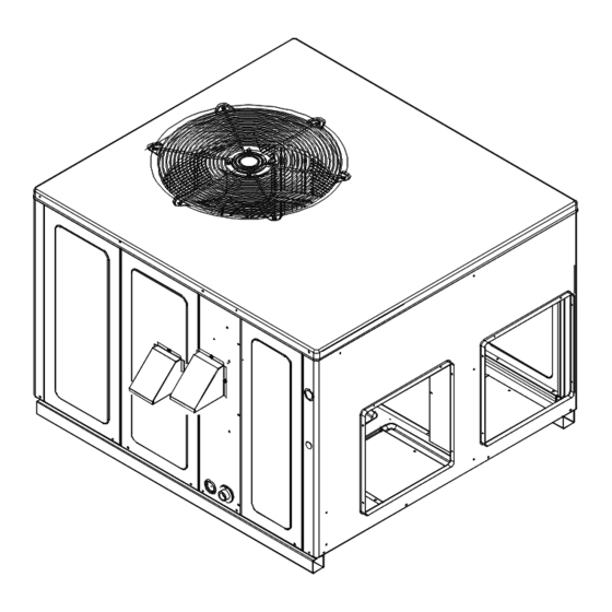
SINGLE PACKAGE GAS-ELECTRIC
HEATING & COOLING UNIT
WARNING
19001 Kermier Rd., Waller, TX 77484
www.goodmanmfg.com • www.amana-hac.com
© 2022 Daikin Comfort Technologies Manufacturing, L.P.
is a registered trademark of Maytag Corporation or its related companies and is used
under license. All rights reserved.
This Forced Air Central Unit Design Complies With
Requirements Embodied In The American National
Standard / National Standard of Canada Shown Below.
ANSI Z21.47•CSA-2.3 Central Furnaces.
RECOGNIZE THIS SYMBOL AS
A SAFETY PRECAUTION.
These installation instructions cover the outdoor installa-
tion of self contained package air conditioners and heating
model for information regarding accessories.
*NOTE: Please contact your distributor or our website
manual.
WARNING
Advertisement
Table of Contents

Related Manuals for Amana APG M Series


Summary of Contents for Amana APG M Series
- Page 1 *NOTE: Please contact your distributor or our website manual. WARNING 19001 Kermier Rd., Waller, TX 77484 www.goodmanmfg.com • www.amana-hac.com © 2022 Daikin Comfort Technologies Manufacturing, L.P. IOG-3024 is a registered trademark of Maytag Corporation or its related companies and is used under license.
-
Page 2: Table Of Contents
TABLE OF CONTENTS REPLACEMENT PARTS ..........2 ............23 ............2 .....23 SAFETY INSTRUCTIONS ..........2 ....23 ............2 GENERAL INFORMATION ..........5 ............23 ...........5 ..23 UNIT LOCATION ..............6 ............24 ............6 ACCESSORIES AND FUNCTIONAL PARTS ....24 ......6 ........24 ........6 .............24 ........7 ..........24 RIGGING DETAILS ............7 APPENDIX ..............31 GAS PIPING ..............7 UNIT DIMENSIONS ............31 ..8... - Page 3 WARNING WARNING - WHAT TO DO IF YOU SMELL GAS: WARNING • • • • WARNING CARBON MONOXIDE POISONING HAZARD WARNING WARNING WARNING HIGH VOLTAGE...
- Page 4 AVERTISSEMENT WARNING FIRE OR EXPLOSION HAZARD AVERTISSEMENT WARNING CARBON MONOXIDE POISONING HAZARD AVERTISSEMENT...
-
Page 5: General Information
Goodman® brand products or 2. Notify carrier promptly and request an inspection. www.amana-hac.com for Amana® brand products. Within 3. In case of concealed damage, carrier should be noti- either website, please select the residential or commercial products menu and then select the submenu for the type 4. -
Page 6: Unit Location
UNIT LOCATION • water from higher ground can collect in the unit. • The top of the unit should be completely unobstructed. WARNING If units are to be located under an overhang, there should be a minimum of 48” clearance and provisions overhang. -
Page 7: Rigging Details
• Class A, Class B, or Class C roof covering material. • for service personnel should be provided. Refer to the Roof Curb Installation Instructions for proper • curb installation. Curbing must be installed in compliance to locating and mounting the curb and package unit. •... - Page 8 The rating plate is stamped with the model number, type of The rating plate is stamped with the model number, type of gas and gas input rating. Make sure the unit is equipped to gas and gas input rating. Make sure the unit is equipped to operate on the type of gas available.
-
Page 9: Propane Gas Installations
WARNING IS NO OPEN FLAME IN THE VICINITY DURING AIR BLEEDING. PROPANE GAS INSTALLATIONS WARNING For Natural gas to LP gas conversion, Conversion Kit CAUTION All propane gas equipment must conform to the safety • For satisfactory operation, propane gas supply pressure must be within 9.7 - 10.3 inches W.C. -
Page 10: Electrical Wiring
See below for typical propane gas piping. ELECTRICAL WIRING First Stage Regulator Continuous 11" W.C. has good air circulation. Movement of air must not be obstructed by furniture, door, 200 PSIG Second Stage Maximum Regulator draperies, etc. The thermostat must not be mounted where television, etc. - Page 11 Thermostat Two-Stage Heating with Two-Stage Cooling Furnace Integrated Control Module R C W1W2 G Y1 Y2 To use a single stage thermostat, move jumper located to the left of the terminal strip labeled “Stage Delay” from NONE to “5” or “10” minutes. This selection will cause the cooling and heating modes.
-
Page 12: Circulating Air And Filters
NOTE: DO NOT use gas piping, or conduit as an electrical ground. Low voltage wiring from the unit control panel to the ther- mostat requires coded cable. See below for ground level and rooftop wiring. Cut insulation around bottom openings and remove panels from the bottom of the unit, saving the screws holding the panels in place. -
Page 13: Condensate Drain
1. Locate the second hood. CAUTION 2. Using the three screws provided, attach the hood access door. Filters installed external to the unit should be sized in accordance with their manufacturer recommendations. A of 300 feet per minute. Filter Installation IMPORTANT: CONDENSATE DRAIN Unit... -
Page 14: Startup, Adjustments, And Checks
3. The spark igniter and gas valve energizes for 7 Two-Stage Models: seconds. NOTE: The igniter produces a very intense electrical spark that ignites the gas. allows additional cooling from the indoor coil to be trans- 4. Main burners light and control detects presence of ferred to the conditioned space. - Page 15 9. Replace the heat exchanger door on the side of the unit. Rollout Protection 10. Open the manual gas valve external to the unit. 11. Turn on the electrical power supply to the unit. 12. Set the thermostat to desired setting. Gas Supply And Manifold Check Gas supply pressure and manifold pressure with the burn- Secondary Limit Control...
- Page 16 The line pressure supplied to the gas valve must be within the Adjust supply pressure using the Inlet Gas Supply supply pressure can be measured at the gas valve inlet pres- Pressure table shown below. If supply pressure read- The supply pressure must be measured with the unit OFF. To ments to pressure regulator, gas piping size, etc., and/ measure inlet pressure, use the following procedure.
- Page 17 WARNING HIGH VOLTAGE Mode This valve is shipped from the factory with the regulator Consult the appliance rating plate to ensure burner man- required, follow these steps. external to the unit. 2. Turn OFF all electrical power to the system. Single Stage Models Remove regulator cover screw from the outlet pressure regulator and turn screw clockwise to increase pressure or...
- Page 18 2. With the unit operating, time the smallest dial on the meter for one complete revolution. If this is a 2 cubic foot dial, divide the seconds by 2; if it is a 1 cubic foot dial, use the seconds as is. This gives the seconds With a properly designed system, the proper amount of per cubic foot of gas being delivered to the unit.
- Page 19 Blower Speed Adjustments Refer to the wiring diagram in the appendix to verify speed LO C OO L tap settings. H I CO OL LO H EA T All models are equipped with EEM motors. EEM motors are H I H EAT constant torque motors with very low power consumption.
- Page 20 Refrigerant Charge Check from the expansion valve, locate the adjustment screw, the unit’s refrigerant charge must be checked. The unit comes factory charged, but this charge is based on 325 CFM per ton and minimum ESP per AHRI test conditions Replace adjustment cap.
-
Page 21: Troubleshooting
External Lockout Design Superheat & Subcool An external lockout occurs if the integrated ignition control Outdoor Superheat Subcooling Expansion Cooling Model Ambient determines that a measurable combustion cannot be estab- ±2°F ±1°F Device Stage (°F ) *PGM324***41 Piston high *PGM330***41 Piston high tion, the gas valve is de-energized, 15 second inter-purge... - Page 22 Rollout Limit Pressure Switch Stuck Open A pressure switch stuck open can be caused by a faulty pressure switch, faulty wiring, a disconnected or damaged blocked or cracked heat exchanger, a failed induced draft blower. If the control senses an open pressure switch during the device is a manual reset limit located on the burner brack- pre-purge cycle, the induced draft blower only will be ener- corrected before resetting the limit.
-
Page 23: Maintenance
MAINTENANCE WARNING by the fuel or combustion air supply, can be removed by NOTE: After cleaning, the microamp signal should be stable and in HIGH VOLTAGE the range of 4 - 6 microamps DC. Flame Sensor Have the gas heating section of the unit checked at least once a year before the heating season begins, to be sure blocked by debris, which would prevent adequate combus- tion air and a properly operating vent system. -
Page 24: Accessories And Functional Parts
CAUTION Check the burner flames for: 1. Good adjustment CAUTION For further information on the yearly inspection, consult the WARNING inspect and service the unit at least once each year. Turn the unit on at the thermostat. Wait a few minutes, ance. - Page 25 BLOWER PERFORMANCE DATA A/GPGM32404041 - Rise Range: 25° - 55° T4 COOLING T5 COOLING T1 HEATING SPEED T2 HEATING SPEED T3 HEATING SPEED E.S.P. SPEED SPEED WATTS RISE WATTS RISE WATTS RISE WATTS WATTS 1,050 1,020 1,119 1,010 1,110 1,083 1,052 1,017 A/GPGM32406041 - Rise Range: 30°...
- Page 26 BLOWER PERFORMANCE DATA A/GPGM33604041** - Rise Range: 25° - 55° T4 COOLING T5 COOLING T1 HEATING SPEED T2 HEATING SPEED T3 HEATING SPEED E.S.P. SPEED SPEED WATTS RISE WATTS RISE WATTS RISE WATTS WATTS 1,115 1,265 1,448 1,440 1,075 1,230 1,403 1,390 1,030...
- Page 27 BLOWER PERFORMANCE DATA A/GPGM34806041 - Rise Range: 30° - 60° T4 COOLING T5 COOLING T1 HEATING SPEED T2 HEATING SPEED T3 HEATING SPEED E.S.P. SPEED SPEED WATTS RISE WATTS RISE WATTS RISE WATTS WATTS 1,055 1,380 1,415 1,851 1,780 1,000 1,320 1,360 1,803...
- Page 28 BLOWER PERFORMANCE DATA A/GPGM36108041 - Rise Range: 30° - 60° T1 LOW STAGE HEATING T2 HIGH STAGE HEATING T3 LOW STAGE T4 HIGH STAGE T5 COOLING E.S.P. SPEED SPEED HEATING SPEED COOLING SPEED SPEED WATTS RISE WATTS RISE WATTS WATTS WATTS 1,285 1,370...
- Page 29 IGNITION CONTROL DIAGNOSTIC INDICATOR CHART Red Light Signal Refer to Abnormal Heating or Cooling Operation Sections of this Manual 1 Flash External Lockout 2 Flashes Pressure Switch Stuck Open 3 Flashes Pressure Switch Stuck Closed 4 Flashes Thermal Protection Device Open HEATING TIMING CHART 100 % Circulator...
- Page 30 IGNITION CONTROL DIAGNOSTIC INDICATOR CHART Red Light Signal Refer to Abnormal Heating or Cooling Operation Sections of this Manual 1 Flash External Lockout 2 Flashes Pressure Switch Stuck Open 3 Flashes Pressure Switch Stuck Closed 4 Flashes Thermal Protection Device Open Amber Light Signal Refer to Abnormal Heating or Cooling Operation Sections of this Manual Normal Flame...
-
Page 31: Appendix
APPENDIX UNIT DIMENSIONS Unit Dimensions (Inches) Model Height Chassis Size A/GPGM324***41** 34 1/2 Medium A/GPGM330***41** 34 1/2 Medium A/GPGM336***41** 34 1/2 Medium A/GPGM342***41** 34 1/2 Medium A/GPGM348***41** 42 1/2 Large A/GPGM361***41** 43 1/2 Large POWER WIRE ENTRANCE 1.375 4.125 2.125 RETURN 4.75 CONDENSATE DRAIN CONNECTION... -
Page 32: Wiring Diagrams
A/GPGM3 [24/30/36] ***41 WIRING DIAGRAM HIGH VOLTAGE! DISCONNECT ALL POWER BEFORE SERVICING OR INSTALLING THIS UNIT. MULTIPLE POWER SOURCES MAY BE PRESENT. FAILURE TO COMP CH OPTIONAL CONNECTED AT L1, L2 CH OPTIONAL NOTE 3 SEE NOTE 3 POWER SUPPLY 208-230/1/60 SEE NOTE 1 SEE NOTE 6... - Page 33 A/GPGM3 [24/30/36] ***41 WIRING DIAGRAM HIGH VOLTAGE! DISCONNECT ALL POWER BEFORE SERVICING OR INSTALLING THIS UNIT. MULTIPLE POWER SOURCES MAY BE PRESENT. FAILURE TO Wiring is subject to change. Always refer to the wiring diagram on the unit for the most up-to-date wiring.
- Page 34 A/GPGM3[42/48]***41 WIRING DIAGRAM HIGH VOLTAGE! DISCONNECT ALL POWER BEFORE SERVICING OR INSTALLING THIS UNIT. MULTIPLE POWER SOURCES MAY BE PRESENT. FAILURE TO COMP CH OPTIONAL CONNECTED AT L1, L2 CH OPTIONAL NOTE 3 SEE NOTE 3 POWER SUPPLY 208-230/1/60 SEE NOTE 5 NOTE 2 L G N RD YL...
- Page 35 A/GPGM3[42/48]***41 WIRING DIAGRAM HIGH VOLTAGE! DISCONNECT ALL POWER BEFORE SERVICING OR INSTALLING THIS UNIT. MULTIPLE POWER SOURCES MAY BE PRESENT. FAILURE TO COMPONENT LEGEND SUPPLY VOLTAGE AUXILLARY LIMIT SW ITCH 208-230/1/60 COMP COMPRESSOR NOTE 3 CONDENSERMOTOR WIRING CONTACTOR CRANKCASE HEATER H IGH VOLTAGE EVAPORATOR MOTOR L OW VOLTAGE...
- Page 36 A/GPGM361***41 WIRING DIAGRAM HIGH VOLTAGE! DISCONNECT ALL POWER BEFORE SERVICING OR INSTALLING THIS UNIT. MULTIPLE POWER SOURCES MAY BE PRESENT. FAILURE TO SEE NOTE 6 SEE NOTE 3 COMP POWER SUPPLY BL BK 208-230/1/60 SEE NOTE 3 SEE NOTE 2 HIGH PARK INDUCER...
- Page 37 A/GPGM361***41 WIRING DIAGRAM HIGH VOLTAGE! DISCONNECT ALL POWER BEFORE SERVICING OR INSTALLING THIS UNIT. MULTIPLE POWER SOURCES MAY BE PRESENT. FAILURE TO FACTOR Y WIRING COM PONENT LEGEND AUXILLARY LIMIT SWITCH LINE VOLTAGE TRANSFORMER HIGH SUPPLY VOLTAGE COMP COMPRESSOR LOW VOLTAGE 208-230/1/60 HLO HI LIMIT OUTPUT CONDENSER MOTOR...
- Page 38 PACKAGE UNITS - DUAL FUEL & GAS WARNING The bearings on the air circulating blower motor, condenser motor and the combustion fan motor are permanently lubricat- ed and require no further lubrication. HIGH VOLTAGE The compressor motor is hermetically sealed and does not require additional oiling.
-
Page 39: Start-Up Checklist
START-UP CHECKLIST Residential Package - (Indoor Section) Model Number Serial Number ELECTRICAL Line Voltage (Measure L1 and L2 Voltage) L1 - L2 Secondary Voltage (Measure Transformer Output Voltage) R - C Blower Amps Heat Strip 1 - Amps Heat Strip 2 - Amps BLOWER EXTERNAL STATIC PRESSURE Return Air Static Pressure IN. - Page 40 19001 Kermier Rd., Waller, TX 77484 www.goodmanmfg.com • www.amana-hac.com © 2022 Daikin Comfort Technologies Manufacturing, L.P. is a registered trademark of Maytag Corporation or its related companies and is used under license. All rights reserved.
Need help?
Do you have a question about the APG M Series and is the answer not in the manual?
Questions and answers