Table of Contents
Advertisement
Quick Links
Advertisement
Table of Contents

Related Manuals for Wyrestorm MX-0404-SCL


Summary of Contents for Wyrestorm MX-0404-SCL
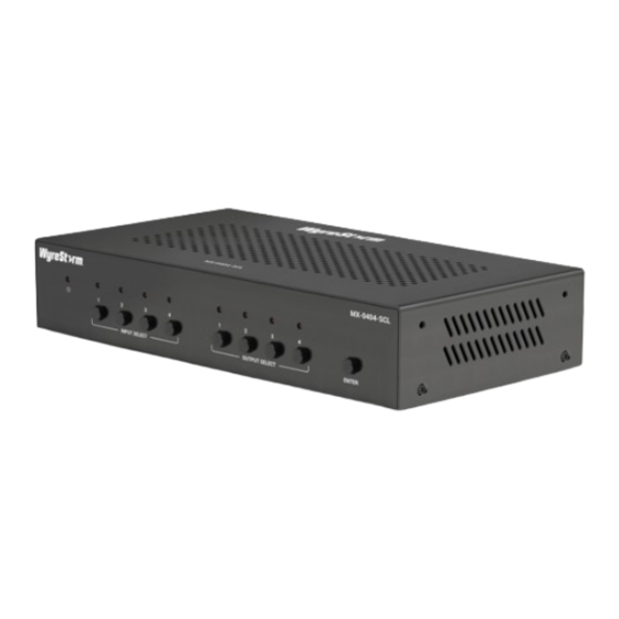
- Page 1 MX-0404-SCL 4K 4x4 Seamless Matrix Switcher User Manual Version: V1.0.0...
-
Page 2: Table Of Contents
Table of Contents Introduction ..................... 3 Overview ....................3 Features ....................3 Package Contents ................... 4 Specifications ................... 4 Panel Description ..................6 Installation and Wiring ..................8 Installation ....................8 Wiring ...................... 9 Button Control ....................10 IR Control .......................10 Command Control .................. - Page 3 Change Login Password ..............21 Network ..................21 Custom Web UI Logo ..............22 System Version ................22 FW Update ..................22 System ..................... 23 Log ....................23 Firmware Upgrade ..................24...
-
Page 4: Introduction
Introduction Overview This product is a full 4K 4 x 4 HDMI seamless matrix switcher. It features compact enclosure, instant switching and free scaling up to 4K@60Hz SDR and HDR. It allows four sources to be switched to four HDMI outputs, while providing both analog and digital S/PDIF audio de-embedding for outputs 1&2. -
Page 5: Package Contents
scaler, manual scaler and video bypass. • Can be easily managed and controlled through front panel buttons, IR, RS232, web UI and TCP protocols. • Supports firmware upgrade through web UI and Micro USB port. Package Contents • 1 x Matrix Switcher •... - Page 6 Technical Dolby TrueHD, Dolby Atmos, DTSHD Master Audio and DTS:X • AUDIO OUT: Balance stereo audio • S/PDIF OUT: PCM 2.0/5.1, Dolby digital and DTS up to 5.1 Channel Maximum Data Rate 18Gbps Front Panel Buttons, RS232, IR, LAN (Telnet &Web Control Method General Operating...
-
Page 7: Panel Description
Panel Description Front Panel Name Description • On: The device is powered on. Power LED • Off: The device is powered off. Input selection LEDs and buttons for input ports (1-4). • LED On: The input port is selected. • LED Blinking: The input port is routed to a specific INPUT output. - Page 8 Rear Panel Name Description Connect to the power adapter and AC power cord provided for power input. HDMI IN (1-4) Connect to the HDMI source devices. HDMI OUT Connect to the HDMI display devices. (1-4) Connect to the PC for firmware (ARM module) upgrade.
-
Page 9: Installation And Wiring
Installation and Wiring Warnings: • Before installation and wiring, disconnect power from the device. • During wiring, connect and disconnect the cables gently. Installation 1. Attach the bracket to one side of the enclosure using the screws provided. The bracket is attached to the enclosure as shown. -
Page 10: Wiring
Wiring... -
Page 11: Button Control
Button Control Users can perform basic switching of input sources to output displays using front panel buttons. To select an input source for the output display: 1. Press one or multiple buttons of OUT 1-4 to select output port(s). The LED will light up once specific output port is selected. -
Page 12: Command Control
1. Connect the IR receiver cable to the IR EXT. port at the rear panel of the device. 2. Select the target output display from the column 1-4. 3. Press the target input port number or previous ( ) / next ( ) button to select the desired input source. -
Page 13: Obtain Ip Address Of The Device
• port: The device’s port number, this is non-required for some Telnet control tools. Default setting is 23. For example, if the device’s IP address is 192.168.11.143, the command for telnet connection shall be the following: telnet 192.168.11.143 Obtain IP Address of the Device To obtain the device’s IP address: Connect a control PC to the RS232 port of the device. -
Page 14: Web Ui
Note: When all is configured properly, you can control the device through commands, which are available in the separate document “API Command Set_MX0404-N301-A00”. Web UI The Web UI designed for this device allows for basic controls and advanced settings. It can be accessed through a modern browser, e.g. -
Page 15: Matrix Control
The main page consists of three tabs: Matrix Control, General Setting, Advanced Setting. Matrix Control Video Matrix Control This section manages distribution of input sources to output displays. Click the button in the table to select the input for the output display (button turns from white to green once selection is done). -
Page 16: Hdmi A/V Mute
• CEC Control: ⇨ On: Click to power on the display connected to the output selected through CEC. ⇨ Off: Click to power off the display connected to the output selected through CEC. • Video Details: Click to view detailed information of input and output ports including status, resolution, framerate, etc., see following: HDMI A/V Mute... -
Page 17: De-Embedded Audio Mute
De-embedded Audio Mute • ON: Select to mute de-embedded audio for selected audio output ports. • OFF: Select to unmute de-embedded audio for selected audio output ports. Default setting: OFF Scaling This section manages scaler configurations for Output 1-4. Three operation options are provided for each output scaler. -
Page 18: Presets Matrix Control
Presets Matrix Control This section saves or loads the settings of or to Video Matrix Control section. • Save: Click to save settings of Video Matrix Control section. • Load: Click to load settings to Video Matrix Control section. To save a setting of Video Matrix to Preset 1: Complete the input and output routing in Video Matrix Control section. -
Page 19: Advanced Setting
This section allows you to change to new output ports’ names. • Save: Click to save and apply all changes. • Reset: Click to reset all changes. Note: The length of each new name shall not exceed 15 characters. Advanced Setting Lower Power Mode This section provides setting of Lower Power Mode. -
Page 20: Edid Read
• Copy From Output 4 • 4K60 2.0CH PCM Audio with HDR • 4K60 2.0CH PCM Audio with SDR • 4K30 2.0CH PCM Audio with HDR • 4K30 2.0CH PCM Audio with SDR • 1080p@60Hz 2.0CH PCM Audio with HDR •... -
Page 21: Cec Control
CEC Control • Display On: Click to power on the display connected to the output selected. • Display Off: Click to power off the display connected to the output selected. • Auto On/Off: Select to enable or disable CEC Auto Control. Default setting: Off •... -
Page 22: Change Login Password
Change Login Password This section is to change login password. Default setting: admin Note: Password must be 4 to 16 characters in length, alphanumeric only. Network This section is to set between the static and dynamic IP address. • IP Type: ⇨... -
Page 23: Custom Web Ui Logo
Custom Web UI Logo This section allows you to create your own logo for the Web UI. To create customized Web UI logo: click “Browse” for the new logo file, and choose “Apply”. Note: The new logo used should be in PNG format and less than 300x60 pixels. -
Page 24: System
Note: • The device will reboot automatically when firmware update is completed successfully. Please wait for about 2-3 minutes, then refresh and log in again. • DO NOT power off the device during the updating process. System • Reboot: Click to reboot device. •... -
Page 25: Firmware Upgrade
Firmware Upgrade The device supports firmware upgrade through web UI and micro-USB port on rear panel. To upgrade firmware through Web UI, see FW Update section. To upgrade firmware through micro-USB port, perform the following: 1. Download the upgrade file on your local PC. 2. - Page 26 When the upgrade process is completed, the device will reboot. Note: Do not cut off the power during the upgrade process. •...
Need help?
Do you have a question about the MX-0404-SCL and is the answer not in the manual?
Questions and answers