
Related Manuals for EG4 LuxPowerTek 6000XP


Summary of Contents for EG4 LuxPowerTek 6000XP
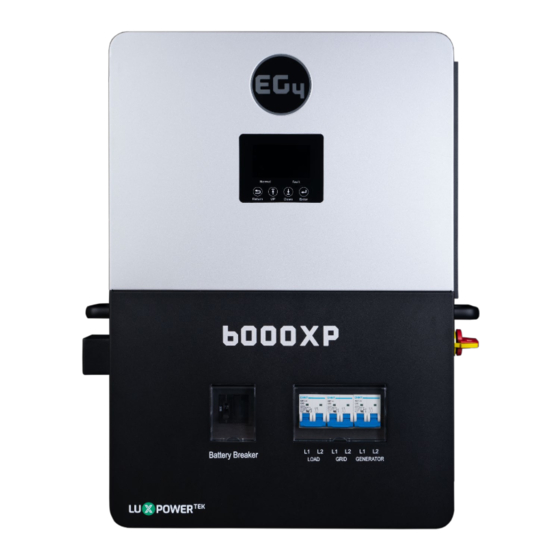
- Page 1 O F F - G R I D I N V E R T E R SCAN FOR UPDATED DOCUMENTS 6000XP © 2023 EG4 ELECTRONICS, LLC. ALL RIGHTS RESERVED. VERSION 1.1.7 | INFORMATION SUBJECT TO CHANGE WITHOUT NOTICE. MODEL #: EG4-6000XP...
-
Page 2: Table Of Contents
TABLE OF CONTENTS ABBREVIATIONS................................1 SAFETY .................................... 2 SAFETY INSTRUCTIONS ............................. 2 IMPORTANT SAFETY NOTIFICATIONS......................2 BRIEF INTRODUCTION..............................4 INVERTER FEATURES ............................4 INVERTER INTERFACE ............................5 STORAGE INFORMATION ........................... 6 INSTALLATION ................................7 PACKING LIST .................................7 LOCATION SELECTION AND INSTALLATION ....................7 4.2.1 REQUIREMENTS FOR INSTALLATION LOCATION .................7 4.2.2... - Page 3 DASHBOARD (OVERVIEW TAB) ....................... 33 7.3.5 DASHBOARD (MAINTENANCE TAB) ...................... 34 FIRMWARE UPDATES ..............................35 FIRMWARE UPDATE VIA EG4 ELECTRONICS APP ..................35 FIRMWARE UPDATE VIA MONITOR CENTER (WEBSITE) ............... 36 SMARTPHONE APP SETUP ............................37 10. OPERATION GUIDE ..............................38 10.1...
-
Page 4: Abbreviations
ABBREVIATIONS • AWG – American Wire Gauge • A – Amp(s) • Ah – Amp hour(s) • AC – Alternating Current • AHJ – Authority Having Jurisdiction • ANSI – American National Standards Institute • BMS – Battery Management System •... -
Page 5: Safety
2. SAFETY SAFETY INSTRUCTIONS International safety regulations have been strictly observed in the design and testing of the inverter. Before beginning any work, carefully read all safety instructions, and always observe them when working on or with the inverter. The installation must follow all applicable national or local standards and regulations. - Page 6 During operation, only the LCD and buttons should be touched. DISCLAIMER EG4 reserves the right to make changes to the material herein at any time without notice. Please refer to www.eg4electronics.com...
-
Page 7: Brief Introduction
3. BRIEF INTRODUCTION INVERTER FEATURES Applicable for purely off-grid inverter/backup power situations. • Integrated with 2 MPPT solar charge controllers with maximum PV input of 480V with an • optimal range of 120VDC-385VDC. Additional safety features such as PV Arc Fault Protection and PV Ground Fault Protection. •... -
Page 8: Inverter Interface
3.2 INVERTER INTERFACE... -
Page 9: Storage Information
3.3 STORAGE INFORMATION If placing the inverter into storage before installation, please keep the following factors in mind when selecting a storage location. 1. The inverter and its components must be stored in its original packaging. 2. The storage temperature should remain within -13 – 140°F (-25 – 60°C), and humidity within 0- 85%. -
Page 10: Installation
4. INSTALLATION PACKING LIST When the product is unpacked, the contents should match those listed below: Pictures are for reference only, subject to our available products. 4.2 LOCATION SELECTION AND INSTALLATION 4.2.1 REQUIREMENTS FOR INSTALLATION LOCATION 1. The mounting wall should be strong enough to bear the weight of the inverter. 2. -
Page 11: Installing The Inverter
4.2.2 INSTALLING THE INVERTER Mounting Bracket Holes Mounting Template The inverter is designed to be wall-mounted and should be installed on a vertical, solid, mounting surface, such as brick, concrete, or other non-combustible material. Two or more people may be needed to install the inverter due to its weight (≈53 lbs). 4.2.3 MOUNTING STEPS Note: Ensure the surface you are mounting the inverter to can support the weight of the unit,... -
Page 12: Connection Overview
4.3 CONNECTION OVERVIEW 4.3.1 SYSTEM CONNECTIONS Before connecting any wiring, please remove the bottom cover by removing the 7 screws as shown below. 4.4 PV CONNECTION 4.4.1 CONNECTING PV TO THE INVERTER Install a separate DC circuit breaker/isolator between the inverter and PV module(s). The recommended DC breaker is a 4-pole 600V/20A. -
Page 13: String Sizing
Reminder! Verify the lowest ambient temperature of the installation location. The rated Voc on the solar module nameplate is obtained at STC (77°F/25°C). As the ambient temperature drops, the solar module Voc increases. Please ensure the maximum solar string voltage, corrected at the lowest temperature, does not exceed the inverter’s maximum input voltage of 480VDC. -
Page 14: Pv Wiring Instructions
When sizing strings for each MPPT, they MUST be the same model, brand and # per string (series and parallel). All panels on a series/parallel string should face the same orientation and be exposed to roughly the same shading across the string. Consideration should be placed on string location and wiring order on the racking to minimize shading effects. -
Page 15: Battery Connection
4.5 BATTERY CONNECTION The EG4 6000XP can utilize either Lithium or Lead-Acid batteries. There is a combination of settings that need to be changed depending on the battery type. 4.5.1 BATTERY CABLE CONNECTION Note: For Lead Acid batteries, the recommended charge current is 0.2C Follow the steps below to properly connect your battery wires. -
Page 16: Lithium Battery Communications
2. For the inverter to communicate with the battery BMS, you must change setting 3 to “Li-ion”. The inverter will then switch to a secondary setting. Here, you select your make/model of battery and press enter to register the change. For EG4 batteries, you would select “0” after confirming “Li-ion” as the battery type. -
Page 17: Steps For Ac Connection
4.7.1 GENERATOR SYSTEM CONNECTION The EG4 6000XP can utilize a generator for backup power in the case of Grid failure. When sizing generators to provide both adequate power and frequency, keep in mind that the THD (Total Harmonic Distortion) of the generator must be <3%. It is a good rule of thumb to size your generator for at least 1.5x the output of the inverter to allow for powering loads and charging batteries. -
Page 18: Integrated Dry Contacts
AC output (LOAD) to power loads. The pass-through relay on the inverter Generator terminal (GEN) is 30A. When the generator is on, please ensure the total load and charge current does not exceed 30A. 4.7.2 INTEGRATED DRY CONTACTS This inverter has two dry contact connections that can be used to remotely enable external devices such as a generator. -
Page 19: Generator Start And Stop Settings
Neutral wire from your generator into the N-BUS (Neutral Bus). 4.8 GENERATOR START AND STOP SETTINGS Using the EG4 Monitoring Software, go to the “Maintenance” page where “Remote Set” will be selected automatically. Scroll down to the “Generator Charge”’ section and select the “Generator Charge Type”... -
Page 20: Paralleling Information
4.10 PARALLELING INFORMATION 4.10.1 PARALLEL COMMUNICATION CONNECTIONS The EG4 6000XP inverter supports parallel connections to expand power and energy capacity to suit different usage scenarios. Up to 16 units can be paralleled to reach a capacity of up to 96kW. The parallel communication wiring diagrams are shown below. -
Page 21: End User Settings
“1P-H:P1: 1”, and slave should read “1P-S:P1: 1”. 5. END USER SETTINGS The EG4 Monitor Software can be used to configure the desired functionality of the 6000XP Inverter. The following sections describe the different fields in the Monitor Software GUI and their definitions for those with an end-user account. -
Page 22: Charge Setting
5.2 CHARGE SETTING Charge Current Limit(A): The maximum charge current limitation of the entire system in • DC Amps. Lead Acid Charge Voltage(V): Set bulk charging voltage for Lead Acid batteries. • AC Charge AC Charge: Utility charge configuration. If users want to use grid power to charge their •... -
Page 23: Discharge Setting
6. INSTALLER SETTINGS The EG4 Monitor Software can be used to configure the desired functionality of the 6000XP Inverter. The following sections describe the different fields in the Monitor Software GUI and their definitions for those with Installer account access. -
Page 24: Application Setting
more than 10 minutes, the inverter output will be cut off. Normal / Standby: Select Normal for the inverter to operate normally. Select Standby to • halt all power input and output. Restart Inverter: This restarts the inverter. • Battery ECO Enable: When enabled, the inverter will switch to bypass mode if the battery •... -
Page 25: Charge Setting
Parallel Settings Set System Type: The EG4 6000XP supports paralleling of multiple inverters. • Battery Shared: For paralleled systems, if all inverters connect to same battery bank, • Battery Shared must be enabled. The inverter with battery to inverter communication cable connected will broadcast the battery info to all other inverters. -
Page 26: Discharge Setting
AC Charge End Battery Voltage(V): Battery Voltage at which system will stop charging • batteries from AC. Set this according to the battery requirements. Range is 48-59 VDC. AC Charge Start Battery SOC(%): Battery % SOC at which system will start charging •... -
Page 27: Other Setting
Discharge Cut-off SOC(%): Set this according to the battery requirements. Range is 0-90 • On Grid EOD Voltage(V): The inverter will stop discharging the battery at this Voltage and • will use AC to power loads. On Grid EOD SOC(%): The inverter will stop discharging the battery at this SOC and will •... -
Page 28: Monitor System Setup
7. MONITOR SYSTEM SETUP WI-FI/4G/LAN DONGLE CONNECTION A Wi-Fi/4G/LAN dongle can be used to monitor the inverter and remotely view the monitoring data on a computer or smart phone. You can attach this module by plugging it in to the ‘Wi-Fi’ connector on the inverter and securing it with the 4 Phillips head screws. -
Page 29: Online Monitoring System User Interface
If you have any questions, or to create distributor or installer accounts, please contact support@eg4electronics.com for assistance. See section 9 for detailed instructions on how to access the EG4 Monitor APP, how to register an account, and how to set a Wi-Fi password. - Page 30 Name Description Select which station to view, and then select which unit/dongle to view by Select station choosing a serial number from the dropdown list. first Note: Unchecking the box will only display serial numbers linked to the account. Shows power generated by the solar panels (for AC coupled inverters it shows the power generated by the on-grid inverter).
- Page 31 Name Description This chart shows the power curve for each day, including solar power, battery charge/discharge power and grid Input & Output Power import/export power and consumption. Hovering over an item name will highlight it in the chart. Clicking it will remove it from the list.
-
Page 32: Dashboard (Data Tab)
7.3.2 DASHBOARD (DATA TAB) The Data Tab displays additional detailed data including technical details for PV, battery, grid, and loads, that is helpful for analysis and maintenance. Five categories make up the Data Tab view: "Chart", "Energy", "Data History", "Local data", and "Event History."... - Page 33 Energy Displays how key energy parameters have varied over time. Selecting ‘Month’ will show the energy statistics for each day. • • Selecting ‘Year’ will show energy for each month. Selecting ‘Total’ will show energy for each year. • Name Description E_pv1(kWh) Energy generated by PV string 1...
- Page 34 Name Description Vpv/Ppv To check the MPPT To check the load type and if there is an overload when in load Vo/Po/So mode To check the current state of charge and if the battery is Vb/SOC overcharged or overly discharged. To evaluate Grid performance and to check if working voltage and Vac/Fac frequency range is adjusted to comply with grid...
-
Page 35: Dashboard (Configuration Tab)
Event History The "Event History" section displays a timeline of events. (Notice and Fault events) If there is not a record of a "historical event," the inverter is properly connected and working without any issues. 7.3.3 DASHBOARD (CONFIGURATION TAB) The “Configuration” page is used for users to manage their station, dataloggers and user information. -
Page 36: Dashboard (Overview Tab)
7.3.4 DASHBOARD (OVERVIEW TAB) "Overview" allows EG4 or its distributors to quickly monitor system-wide data for their end users, such as solar yields, battery discharging, and other factors. Station Overview All the stations linked to the account can be found here. -
Page 37: Dashboard (Maintenance Tab)
Distributors can manage all settings for all inverters at once with the help of the batch setting capability supported by EG4's monitor system. Note: If trying to update firmware locally, see Section 8. -
Page 38: Firmware Updates
8. FIRMWARE UPDATES FIRMWARE UPDATE VIA EG4 ELECTRONICS APP NOTE: When updating your firmware through the EG4 APP, be sure to have plenty of battery life on your device and do not close the application. Make sure you have the Wi-Fi dongle connected securely and correctly configured for the inverter before performing the following steps. -
Page 39: Firmware Update Via Monitor Center (Website)
8.2 FIRMWARE UPDATE VIA MONITOR CENTER (WEBSITE) Step 1: Distributors and installers can update the firmware for their inverters by using the EG4 Electronics website monitoring system. Please contact EG4 to make sure you have the correct files. Step 2: Log into the EG4 Electronics Monitor System. Select “Maintenance,” and then select “Remote Update.”... -
Page 40: Smartphone App Setup
Wi-Fi password for the Wi-Fi dongle before using EG4's monitoring system. 1. Register your account Visit https://monitor.eg4electronics.com/ download the ‘EG4 Monitor' app to register for an end-user account. Please contact support@eg4electronics.com for distributor or installer accounts. 2. When registering the account, provide the following information: a. -
Page 41: Operation Guide
Local Monitoring Setup with the EG4 Monitor App If there is no Wi-Fi available at the location, you can use the Bluetooth function on your mobile device to monitor or set up the system. 1. Download the EG4 Monitor app. - Page 42 BAT Off-Grid Battery powers the load PV+BAT Off-Grid PV & Battery power the load 1. With EPS output switch off, the inverter charges the battery only PV Charge 2. With battery power off, PV can wake up the battery automatically PV charges the battery and PV Charge+Off-Grid powers the load...
-
Page 43: Rapid Shutdown (Rsd)
For paralleled systems, the RSD needs only to connect to the master inverter. When the switch is engaged, it will shut down all inverters in parallel past the master. Note: When using supported EG4 batteries in closed-loop communications with the inverter, the RSD also initiates ESS Disconnect as required by NEC code The system can utilize an External E-Stop Switch if your AHJ deems it necessary. -
Page 44: Lcd Display And Settings
10.3 LCD DISPLAY AND SETTINGS The user can wake up the LCD screen by simply pressing the Enter button. System status, real-time power, and daily and accumulated energy information can all be conveniently viewed on the inverter’s LCD screen. Additionally, users can also check the alarm and fault record on the display for troubleshooting. -
Page 45: Lcd Display
10.3.1 LCD DISPLAY The data on the LCD screen updates every 3 seconds as various information is displayed in each section. See table on next page for more details. Description Comments Displays the current system status by default. Pressing the Up/Down buttons will General Information cycle through Time, Date, Single/Parallel Inverter Setting, Inverter Serial Number, Display Area... - Page 46 Inverter Status Displays Warning Status: Normal/Running Status: Flash Status: Fault Status: Grid Status for GRIDA (Utility): Grid Status for GRIDB (Generator): NOTE: When GRIDA is displayed, AC utility information is NOTE: When GRIDB is displayed, Generator information is displayed. Percent at bottom right is % load (e.g. 23%). displayed.
-
Page 47: Lcd Settings
11. LCD SETTINGS There are four (4) buttons on the LCD screen used to select various modes and make changes to settings: Step 1: Press the Enter button for ≈3 seconds to enter the setting mode. The data in the ‘General Information Display Area’... - Page 48 Step 1: Choose battery type first. When “Li-ion” begins flashing, select Enter to operate with Lithium Batteries. Step 2: Enter the Battery Brand (e.g., 0=EG4, 2=Pylon, 6=LuxPower, 8=Dyness) This setting allows the user to set the inverter output voltage and frequency.
- Page 49 This setting allows the user to set the maximum charge current. Total Charge Current: Range: 0 – 125A Default: 125A Maximum Charge Current AC Charge Current: (Utility+Solar) Range: 0 – 125A Default: 30A Generator Charge Current: Range: 0 – 110A Default: 30A This setting allows the user to set the Charging Voltage for...
- Page 50 This setting allows the user to select Voltage or SOC as the trigger for battery discharge. TEOd: Discharge Control Type (Volt/SOC) This setting allows the user to set the cutoff Voltage or SOC based on the selection made in Setting 10, TEOd.
- Page 51 This setting allows the user to set the AC Input Voltage Range AC In Voltage Range: APL – 90-280VAC AC In: UPS – 170-280VAC AC Voltage Range Setting To configure AC charging, the user must first enable AC Charging, confirm the full battery SOC value, and set the confirmation time periods 1, 2, and 3.
- Page 52 This setting allows the user to set the Start/End times for the Grid/Utility to supply power to the load. AC Input Load Timer Settings Start Time1-3: 00:00 – 23:59 Default: 00:00 – 00:00 End Time1-3: 00:00 – 23:59 Default: 00:00 – 00:00 This setting allows the user to enable or disable the battery wakeup feature.
- Page 53 This setting allows the user to enable or disable the Power Save Functions, ‘Green Function’ and ‘ECO Mode’. Power Save Range: Enable/Disable Function The default settings for both functions are set to disabled. This setting allows the user to select the inverter paralleling configuration.
- Page 54 This setting allows the user to adjust the operation of the Inverter’s two fans. The user can set the speed (20-100%) and enable or disable the slope (Enabling the slope allows the fans to ramp up/down to/from the fan speed setting).
- Page 55 This setting allows the user to enable or disable the PV Isolation Protection of the MPPT. Range: Enable/Disable Default: Enable PV Isolation Protection This setting allows the user to enable or disable the RSD function of the inverter. Range: Enable/Disable Default: Enable RSD Function This setting allows the user to...
-
Page 56: Inverter Start-Up And Shut-Down Procedure
12. INVERTER START-UP AND SHUT-DOWN PROCEDURE 12.1 START-UP Follow the steps outlined below to ensure proper start-up and shut-down procedures to avoid potential component damage. 1. Ensure all circuit breakers are in the open (OFF) position. 2. Using a multimeter, check the battery bank to ensure no voltage (DC) is present. 3. -
Page 57: Error/Warning Tables
13. ERROR/WARNING TABLES 13.1 ERROR DEFINITIONS AND TROUBLESHOOTING Code Description Troubleshooting Restart inverter. If error persists, contact E000 Internal Communication Fault your distributor Restart inverter. If error persists, contact E002 Bat On Mos Fail your distributor Restart inverter, if the error persists, contact E003 CT Fail your distributor... -
Page 58: Warning Definitions And Troubleshooting
13.2 WARNING DEFINITIONS AND TROUBLESHOOTING Code Description Troubleshooting Check your battery settings to ensure they are set for your specific battery type. Check your W000 Battery communication failure battery communications cable for proper pinning/installation. Restart Inverter. If the error persists, contact W001 AFCI Com failure your distributor... -
Page 59: Inverter Maintenance
14. INVERTER MAINTENANCE Electrical equipment must be properly maintained to increase longevity and consistency. Follow the steps below to help prevent component damage/deterioration. 1. Inspect the inverter every month to confirm nothing covers the inverters heatsink. If there is, shut down the inverter and clear the heat sink to restore proper cooling. 2. - Page 60 MAXIMUM UTILIZED SOLAR POWER 8000W (4000W per MPPT) RECOMMENDED MAXIMUM SOLAR INPUT 10,000W EFFICIENCY MPPT EFFICIENCY BATTERY CHARGING EFFICIENCY BATTERY DISCHARGING EFFICIENCY w/ PV w/ Battery w/ AC IDLE CONSUMPTION (STANDBY MODE) <30W ≈50W <50W BATTERY DATA TYPE Lead-acid/Lithium MAX. DISCHARGE CURRENT 140A MAX.
- Page 61 VOLTAGE PROTECTION VARISTOR STANDARDS AND CERTIFICATIONS UL1741 FCC PART 15, CLASS B INGRESS PROTECTION RATING IP20 **Idle consumption value tested with constant 300VDC PV source **115A @ 48VDC (AC), 125A @48VDC (PV) See EG4 Warranty Registration for terms and conditions ®...
- Page 62 Notes...
- Page 63 Notes...
- Page 64 CONTACT US EMAIL: support@eg4electronics.com PHONE: +1 (903) 609-1988 WEBSITE: www.eg4electronics.com © 2023 EG4 ELECTRONICS, LLC. ALL RIGHTS RESERVED. VERSION 1.1.7 | INFORMATION SUBJECT TO CHANGE WITHOUT NOTICE. MODEL #: EG4-6000XP...
Need help?
Do you have a question about the LuxPowerTek 6000XP and is the answer not in the manual?
Questions and answers