Table of Contents
Advertisement
Quick Links
Advertisement
Table of Contents

Related Manuals for ABB D1M 20


Summary of Contents for ABB D1M 20
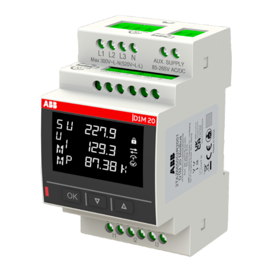
- Page 1 POWER METER D1M 20 User manual...
-
Page 3: Table Of Contents
D1M 20 POWER METER USER MANUAL Table of Contents 1. General information..................... 5 1.1.Use and storage of manuals ..................5 1.2.Copyright ........................5 1.3.Liability disclaimer ....................5 1.4.General safety warnings ..................5 1.5.Cyber Security Disclaimer ..................6 2. Packaging contents ..................... 7 3. Technical characteristics ..................8 3.1.Description of the device ..................8... - Page 4 D1M 20 POWER METER USER MANUAL 8. Data reading (READ)..................53 8.1.Realtime (REAL) ....................54 8.2.Energy (ENRG) .......................55 8.3.Power Quality (PWQT)..................57 8.4.Average values (AVG) ..................58 8.5.Maximum values (MAX) ..................59 8.6.Minimum values (MIN) ..................60 8.7.I/O ..........................61 8.8.Notifications (NOTF) ....................62 8.9.Power Outage (PWOF) ..................
-
Page 5: General Information
1.2.Copyright The copyright of this manual is the property of ABB LV Installation Materials Co. Ltd. Beijing. This manual contains texts, designs and illustrations of a technical nature which must not be disclosed or transmitted to third parties, even partially, without the written authorization of ABB LV Installation Materials Co. -
Page 6: Cyber Security Disclaimer
D1M 20 POWER METER USER MANUAL 1.5.Cyber Security Disclaimer D1M 20 multimeter is designed to be connected and to communicate information and data via a network interface, which should be connected to a secure network. It is your sole responsibility to provide and... -
Page 7: Packaging Contents
D1M 20 POWER METER USER MANUAL 2. Packaging contents Packaging contents Power meter D1M 20 Installation manual Calibration certificate... -
Page 8: Technical Characteristics
D1M series can help users accurately monitor energy efficiency while meeting their cost control requirement. Conforming to the international electric energy metering and monitoring accuracy standards, all D1M series products are perfectly suitable for ABB electrical systems and solutions. 3.2.Main functionalities Real-time Measurement TRMS Current •... -
Page 9: Overall Dimensions
D1M 20 POWER METER USER MANUAL 3.4.Overall dimensions Unit: mm 3.5.Technical data Auxiliary power supply Voltage range 100-230 V AC/DC ±15% Frequency 50 - 60Hz ±5% Power Consumption 5VA max Installation category CAT III 300V class per IEC 61010-1 edition 3... - Page 10 D1M 20 POWER METER USER MANUAL Voltage measurement inputs Voltage input mode Direct or Indirect insertion with VT Measurement Range 80-300 VAC(L-N) Wiring Type Single-phase, three-phase (3P, 3P+N) Rated frequency 50Hz or 60Hz VT primary range 50~750000V VT secondary range...
- Page 11 D1M 20 POWER METER USER MANUAL Modbus TCP/IP D1M 20 Ethernet Communication protocol Modbus TCP/IP Communication interface RJ45 DHCP/Manual, IP Address default 192.168.1.12 DHCP/Manual, Subnet mask default 255.255.255.0 DHCP/Manual, Gateway default 192.168.1.1 Port 502 fixed Standards Power metering and monitoring devices (PMD)
-
Page 12: Installation
D1M 20 POWER METER USER MANUAL 4. Installation 4.1.Assembly 4.2.Disassembly... -
Page 13: Wiring Diagrams
D1M 20 Ethernet Type of network D1M 20 can be used on different type of network (please refer to chapter “7. Configuration (CONF)” the configuration on the device). According to the type of network that has been chosen, the parameters visualized on the device HMI change. - Page 14 D1M 20 POWER METER USER MANUAL • 3-phase 3-wire network with 3CTs (3 3T) 3P3W3CT 3P3W3CT Voltage Voltage L1 L2 L3 N L1 L2 L3 N L1(A) L1(A) L2(B) L2(B) L3(C) L3(C) • 3-phase 3-wire network with 2CTs (3 2T)
-
Page 15: Access To Device
This chapter gives a detailed introduction of the device’s HMI, including how to read data and configure related parameters. 5.1.Display Front panel. D1M 20 products use LCD displayer, the front panel of D1M 20 is shown below: Operator panel Display area Function buttons... - Page 16 D1M 20 POWER METER USER MANUAL Area Description Title Title of the content displayed on each screen The corresponding phase of the measured value displayed, such Phase as L1, L2, L3, L12 and L23… Load type Inductive load and capacitive load, or the negative sign...
-
Page 17: Buttons
Phase Magnitude Load type 5.2.Buttons Each D1M 20 is provided with 3 push buttons as per below picture: Functions of each button might change according to the displayed page on the meter. See below for a complete description: Button Short press functions... -
Page 18: Data Entry
D1M 20 POWER METER USER MANUAL 5.3.Data entry Some of the pages require the entry of numerical characters (0-9) in the Configuration mode. In these cases, the display will show an active field identified by a flashing number. Data entry procedure Press the “OK”... - Page 19 D1M 20 POWER METER USER MANUAL 2. Press “Down” to move the cursor in order to add a second digit to the number. • How to: Enable the comma Some device configurations allow entering the comma. Comma can be displayed by increasing the number with “Up”, after character 9 and before data entry starts again from character 0.
- Page 20 D1M 20 POWER METER USER MANUAL • How to Enter the magnitude Some device configurations allow entering the magnitude (k, M). Once the number has been entered as after step 3, keys “Up” and “Down” allow enabling the magnitude “K” (kilo) or not. Press “OK” to confirm...
-
Page 21: First Commissioning
D1M 20 POWER METER USER MANUAL 6. First commissioning When the device is started up for the first time, the basic parameters need to be set, and the wizard program will guide the user to configure the device by following the steps below:... -
Page 22: Real Time Clock (Rtc)
D1M 20 POWER METER USER MANUAL 6.2.Real Time Clock (RTC) Setting date and time is mandatory in order to use the time-related functionalities on the device (Tariff). Please notice that if no date and time are set, no timestamp will be available on the measured data. -
Page 23: Wiring (Wir)
D1M 20 POWER METER USER MANUAL 6.3.Wiring (WIR) In order to configure the type of network it is needed to choose one of the available options according to the installation conditions. CONF>ISTL>WIRI 1. Scroll the list of fields “Up” or “Down”... -
Page 24: Vt Ratio (Vt)
D1M 20 POWER METER USER MANUAL 6.5.VT ratio (VT) D1M is capable to measure voltage via direct connection up to 300 V (L-N), or via indirect connection by means of voltage transformers. In order to configure the voltage transformer ratio, it is needed to enter manually the values of both primary (PRIM) and secondary (SEC). -
Page 25: Configuration (Conf)
D1M 20 POWER METER USER MANUAL 7. Configuration (CONF) When the user goes to the CONF section, Icon will be displayed. When entering the CONF section, in order to change any configuration of the device, it is mandatory to enter the password. It is needed to enter the password again when customer needs to re-operate after inactivity time. - Page 26 D1M 20 POWER METER USER MANUAL Reset (RST) If the user selects “YES” and presses Button “OK”, all parameters will be reset, i.e. restoring all parameters to their factory default. CONF>UNIT>RST RST sub-menu includes the following pages: Menu Description Reset and Clear everything, restore the device to the factory state except RESET FACTORY for the Audit Log.
- Page 27 D1M 20 POWER METER USER MANUAL • RESET NOTF All notification will be cleared after the reset notification, including alarms, warnings, and errors. CONF>UNIT>RST>NTF • RESET Avg/Max/Min Reset and clear the data of Average, Maximum and Minimum CONF>UNIT>RST>AVG • RESET Global Complete reset of the device except for the settings and the audit log, include notifications, timer, energy, Avg/Max/Min.
- Page 28 D1M 20 POWER METER USER MANUAL Device information (INFO) INFO includes firmware version, product model and peripheral functions, etc. CONF>UNIT>INFO Menu Description Firmware version, contain main board, ethernet board (D1M20 ETHERNET) The CRC value of current firmware inside Serial Number...
- Page 29 D1M 20 POWER METER USER MANUAL Real Time Clock (RTC) RTC shares the same setting way with the same item under the first startup. For details, see “6.2.Real Time Clock (RTC)”. Brightness (BRT) The parameter is used to adjust brightness of the display.
- Page 30 D1M 20 POWER METER USER MANUAL Audit log (ALOG) In this part user can review all audit logs. In the measurements area, select one to review. The audit log items contain the activities as below: CONF>UNIT>ALOG Quantities Value Trigger time...
- Page 31 D1M 20 POWER METER USER MANUAL Home page (HOME PAGE) HOME PAGE can be set as the one of Summary, Phase Voltage, Line Voltage and Current page. It will turn to the home page which was set by users if no activities after inactivity time.
- Page 32 D1M 20 POWER METER USER MANUAL It will return a Homepage after timeout and display every few seconds. If VLN/VLL is configured as the auto scroll page but the connection mode does not support the display of VLN/VLL, the display is not cyclic, the homepage is displayed on the Summary page.
-
Page 33: Installation (Istl)
(CT)” “6.5.VT ratio (VT)”. 7.3.Input/output (I/O) In this section it is possible to configure I/O slots of the meter. D1M 20 series Power meter have two ports of DO and two ports of DI. I/O includes the following sub-menus: Menu... - Page 34 D1M 20 POWER METER USER MANUAL Pulse output Selecting Pulse output, the output is set as a pulse generator associated with a measured parameter. It is needed to consecutively set a measured parameter associated to the pulse output, the pulse ratio, and the pulse length.
- Page 35 D1M 20 POWER METER USER MANUAL Digital input (DI) All DIs can be configured as Pulse Input or Tariff Input. Menu Description Pulse Input Count the pulses and calculate the energy according to the pulse factor Tariff Input Both the 2 ports are used to indicate the current tariff...
-
Page 36: Alarms (Alam)
When the device is in alarm state, ICON will be displayed. Each D1M 20 provides up to 15 alarms; following parameters are available: Menu Description... - Page 37 D1M 20 POWER METER USER MANUAL CONF>ALAM>NUM • “Add” indicates that the alarm is not yet present. If it needs to be added, press the button “OK” to go to the event and configure the subsequent parameters. • “Edit” indicates that the alarm is already present. If it needs to be modified, press the button “OK”...
- Page 38 D1M 20 POWER METER USER MANUAL PHASE When a variable is selected, a specific phase of the variable needs to be selected. CONF>ALAM>PHSE Phase Description Phase 1 Phase 2 Phase 3 Total phase (when PT/QT/ST/PFT is selected variable) Different variables contain different phases, so the phase selection depends on the variable selected.
- Page 39 D1M 20 POWER METER USER MANUAL SETPOINT SETPOINT includes numerical value and magnitude. Different variables correspond to different thresholds, magnitudes, and units, and you need to select variables before setting SETPOINT. Variable Value range Active Power 0~9999MW Active Power Total...
- Page 40 D1M 20 POWER METER USER MANUAL DELAY DELAY is used to verify whether the variable value really exceeds the limit or is recovered, and its setting range is 0~900s. CONF>ALAM>DELAY All alarms are set by default in log mode, which means that alarms are stored in flash memory when the alarm is triggered.
-
Page 41: Tariff (Tarf)
D1M 20 POWER METER USER MANUAL 7.5.Tariff (TARF) There are up to 4 tariffs to monitor consumption in different time phase. If select RTC as the tariff source, it provides 3 kinds of day-type with configurable tariff configurations. TARIF menu as below:... - Page 42 D1M 20 POWER METER USER MANUAL Tariff source It is possible to select from 4 options include NONE (disable)/COMM(communication)/DI (digital input)/ RTC (real time clock). CONF>TARF>TARF SOURCE Tariff RTC set If user select tariff source as RTC, tariff RTC menu will be valid.
- Page 43 D1M 20 POWER METER USER MANUAL • Set Day Type Set Monday/Tuesday/Wednesday…/Sunday as weekday or weekend. CONF>TARF>SET RTC>SET DAY TYPE...
- Page 44 D1M 20 POWER METER USER MANUAL • Set weekday time Enable or disable T1 and set start time(HHMM) of T1, same as T2,T3,T4. CONF>TARF>SET RTC>SET WKDY TIME • Set weekend time Enable or disable T1 and set start time(HHMM) of T1, same as T2,T3,T4.
- Page 45 D1M 20 POWER METER USER MANUAL • Set Special Day Set the total number of special day (0-50). CONF>TARF>SET RTC>SET SPECDAY>TOT After setting the total number of special day, add special day (SPCE DAY) one by one in the format: YY-MM-DD.
- Page 46 D1M 20 POWER METER USER MANUAL And then enable or disable special day T1 and set start time(HHMM) of T1, same as T2,T3,T4 CONF>TARF>SET RTC>SET SPEC TIME Current tariff User could read the tariff (NONE/T1/T2/T3/T4) used currently. CONF>TARF>CURRENT...
-
Page 47: Communication (Comm)
D1M 20 POWER METER USER MANUAL 7.6.Communication (COMM) Comm menu allows to set all the parameters related to the communication protocol available for a specific product version. The embedded communication protocol varies according to the different product versions. Please refer to “3.3.Versions”... - Page 48 D1M 20 POWER METER USER MANUAL • Byte format (BYTE) BYTE comprises three parts – bits per byte, parity bit and stop bit. CONF>COMM>PARITY The optional byte formats include: BYTE Description 8 even parity bits and 1 stop bit 8 odd parity bits and 1 stop bit 8 No Parity bits and 1 stop bit •...
- Page 49 D1M 20 POWER METER USER MANUAL Modbus TCP/IP (D1M 20 Ethernet) • DHCP If DHCP is set as “YES”, it indicates that the IP address and subnet mask assigned by the host will be used. CONF>COMM>DHCP The default state of DHCP is “NO”, i.e. turned off.
- Page 50 D1M 20 POWER METER USER MANUAL • MASK MASK indicates the LAN segment. Only the devices that have the same subnet mask within the same LAN can communicate with each other. CONF>COMM>MASK The default MASK is: 255.255.255.0. • GW The default GW is the node address that forwards the data package to other networks.
-
Page 51: Other (Othr)
D1M 20 POWER METER USER MANUAL 7.7.Other (OTHR) There are some other functions can be set, following settings are available. Setting Description Average Time Interval Calculate the Average/Maximum/Minimum in Average Time Interval. Time Count Down Count down start from this time was set. - Page 52 D1M 20 POWER METER USER MANUAL CO2 Equivalence Converse the Active Energy Import Total to CO2. The factor between the Active Energy Import Total and CO2 range is 0.001~9.999Kg/kWh. CONF>OTHR>EQUI CO2 Currency Equivalence Converse the Active Energy Import Total to Currency. The factor between the Active Energy Import Total and Currency range is 0.001~99999.999Currency/kWh.
-
Page 53: Data Reading (Read)
D1M 20 POWER METER USER MANUAL 8. Data reading (READ) READ section allows to visualize all the parameters measured by D1M. Specifically, it includes the following menus: Menu Description REAL Real-time measurements ENRG Energy measurements PWQT Power quality Average of measurement variable... -
Page 54: Realtime (Real)
D1M 20 POWER METER USER MANUAL 8.1.Realtime (REAL) REAL means the real-time data of the current electric energy, including the following items: READ>REAL REAL Description Summary measurements, average of 3 phases VLL, average of 3 phases I, and active SUMM... -
Page 55: Energy (Enrg)
D1M 20 POWER METER USER MANUAL 8.2.Energy (ENRG) READ>ENRG... - Page 56 D1M 20 POWER METER USER MANUAL ENRG Description T1+PEN Tariff T1 total imported active energy T1+QEN Tariff T1 total imported reactive energy T2+PEN Tariff T2 total imported active energy T2+QEN Tariff T2 total imported reactive energy T3+PEN Tariff T3 total imported active energy...
-
Page 57: Power Quality (Pwqt)
D1M 20 POWER METER USER MANUAL 8.3.Power Quality (PWQT) READ>PWQT PWQT Description Per phase power factor; when WIRI is selected as “3 3T”, “3 2T”, “3 1T” or “1N1T”, this data is absent Total power factor Total harmonic distortion of phase voltage, when WIRI is selected as ‘3 3T’, ‘3 2T’, ‘3 THDV 1T’, this data is absent... -
Page 58: Average Values (Avg)
D1M 20 POWER METER USER MANUAL 8.4.Average values (AVG) AVG represents the average values for instantaneous parameters, calculated over the averaging time (see Average Time Interval sub-menu under “7.7. Other (OTHR)”), including the following items: READ>AVG Description Average phase voltage... -
Page 59: Maximum Values (Max)
D1M 20 POWER METER USER MANUAL 8.5.Maximum values (MAX) In order to access the MAX values, please press simultaneously “OK” and “Up” when in the parameter page in READ/REAL. READ>MAX MAX represents the maximum values for: Description Maximum phase voltage... -
Page 60: Minimum Values (Min)
D1M 20 POWER METER USER MANUAL 8.6.Minimum values (MIN) In order to access the MIN values, please press simultaneously “OK” and “Down” when in the parameter page in READ/REAL. READ>MIN MIN represents the minimum values for: Description Minimum phase voltage... -
Page 61: I/O
D1M 20 POWER METER USER MANUAL 8.7.I/O I/O sub-menu includes the reading of status and/or pulses for I/O, according to the product version: Menu Description DO STATE State of digital output port DO1 PULSE DO1 Pulse counter DO2 PULSE DO2 Pulse counter... -
Page 62: Notifications (Notf)
D1M 20 POWER METER USER MANUAL 8.8.Notifications (NOTF) NOTF includes the following items: Menu Description ALARM Alarm list, Related to the alarm status and information WARN Warnings list, related to installation conditions and device settings. ERROR Errors list, related to the device and to its self-diagnostics. - Page 63 D1M 20 POWER METER USER MANUAL Warnings (WARN) WARN is generated when the device detects the operating conditions. When there is a WARN notification, Icon will be displayed; and when there is no warn messages, Icon will disappear. WARN comprises warn count and specific warn message.
- Page 64 D1M 20 POWER METER USER MANUAL Errors (ERR) ERR is generated when the device detects operating fatal conditions. When there is an ERROR notification, Icon will be displayed and it will not disappear until the error is solved. ERROR comprises error count and specific error message.
-
Page 65: Power Outage (Pwof)
D1M 20 POWER METER USER MANUAL 8.9.Power Outage (PWOF) PWOF is used to record the number and time of power outage. The maximum record number is 999. READ>NOTF>PWOF 8.10.Timers (TIME) TIME uses the hour of RTC to count these 2 counters below. -
Page 66: Conclusion
D1M 20 POWER METER USER MANUAL 9. Conclusion Thank you for using ABB D1M 20 series Power Meter and reviewing this user manual. In the future, if you encounter any problems, please contact ABB technical support, we will be happy to help you. - Page 67 ......................................................................................................................................................................................................................................................................................................................................................................................................................................................................................................................................................................................................................................................................................................................................................................................................................................................................................................................................................................................................................................................................................................................................................................................................................................................................................................................................................................................................................................................................................................................................................................................................................................................................................................
- Page 68 ABB LV Installation Materials Co. Ltd. Beijing Electrification Business Area No. 17 Kangding Street, Beijing Economic-Technological Development Area 100176 www.abb.com/low-voltage 中国地区服务电话:400-820-9696...