
Related Manuals for Woodway CURVE LTG


Summary of Contents for Woodway CURVE LTG
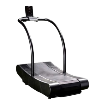
- Page 1 For The Long Run CURVE LTG - Owners Manual Owners Manual woodway.com 08.30.23 OM-EN-V1...
- Page 2 The release of the operating instructions to third parties without the written permission of WOODWAY is prohibited. Duplication in any manner and form - including excerpts - as well as use and/or communication of the content are not permitted without written permission from WOODWAY.
-
Page 3: Table Of Contents
Upright Transportation ..............17 Transportation with Carrying Poles ..........18 Storage ..................18 Dimensions and Technical Specifications ..... 18 Curve LTG Model................19 Conditions for Use ............... 19 Setup and Placement ........19 General ..................19 Preparation and Placement ............20 Safe Fall Area ................ - Page 4 7.3.7 Calculating Heart Rate Measurement ............38 7.3.8 Heart Rate Monitors ................... 39 7.3.9 Applying the Chest Strap ................39 7.3.11 Before Each Use ................40 7.3.12 Starting the Treadmill ................40 Control Console ............41 Control Console Overview ................41 Description of Lower Control Console Buttons ..........
- Page 5 08.30.23 OM-EN-V1...
- Page 6 Sporthochschule in Cologne, Germany), Willi developed and patented a very unique and revolutionary treadmill design. In 1975, WOODWAY GmbH was founded in Weil am Rhein, Germany. The name “WOODWAY” is derived from the German “Waldweg” (“Wald” = wood and “Weg”= way), the feel of running on a soft pine needle covered path in the forest.
-
Page 7: Safety
It is imperative that all users familiarize themselves with the treadmill and its features. The Curve LTG belt moves freely, by stepping on the rear-most part of the running surface where it is rounded, there is a danger of falling, as the force of gravity can set the running surface in motion. - Page 8 • WOODWAY treadmills are built to handle runners weighing up to 800 lbs. (360 kg) at speeds between 0-4 MPH (0-6.5 km/h) and 400 lbs. (180 kg) at speeds greater than 4MPH (6.5 km/h).
-
Page 9: Description Of Warning Notices
Description of Warning Notices Warning notices indicate potential hazards or safety risks. They are indicated in this manual by a color-coded signal word panel (symbol with the appropriate signal word). All warning notices have the same design and the same standardized content design. Sample of a Warning Notice SIGNAL WORD Warning Text, Type, and Source of Danger... -
Page 10: Personnel Qualifications And Responsibilities
The Curve LTG treadmill is non-motorized, it serves for training athletic running, to increase stamina and physical fitness, and can be used for running or walking. Please note that the Curve LTG listed in this manual is athletic training equipment, which according to EU regulations are not to be used for medical applications. -
Page 11: Unauthorized Modes Of Operation
It is forbidden to use the treadmill without its side rails or with walking poles. • The operation of WOODWAY slat belt treadmills outside of the named ambient conditions in the section “Setup & Installation” (temperature, humidity, air pressure) as well as outdoors (i.e. -
Page 12: Introduction
Introduction Operating Instructions Information This manual provides information on the safe operation of the WOODWAY slat belt treadmill. A condition for safe operation is compliance with all safety and operating instructions. CAUTION Improper Operation Can Cause Accidents! • Not using the treadmill as intended according to the manufacturer’s instructions can cause accidents and equipment damage. -
Page 13: Replacement Parts
Name Plate: Each WOODWAY treadmill receives a serial number during production. Depending on the year of your model, it has an alphanumeric code with 7-8 characters or a numeric code with 9 digits. - Page 14 Warning: Changes or modifications to this unit not expressly approved by the party responsible for compliance could void the user’s authority to operate the equipment. NOTE: This equipment has been tested and found to comply with the limits for a Class B digital device, pursuant to Part 15 of the FCC Rules.
- Page 15 If this manual has been printed, write the Serial Number, Model Number and Model Code in the spaces below, as they will be needed when contacting the WOODWAY service department. Serial Number: _________________________________ Model Number: _________________________________ Model Code ____________________________________ 1) Device CE symbol with number of the notified body if applicable, and Year Manufactured.
-
Page 16: Ec Declaration Of Conformity
EC Declaration of Conformity 08.30.23 OM-EN-V1... -
Page 17: Transportation And Storage
For further information please contact WOODWAY Customer Service. Flat Transportation The Curve LTG treadmill can be transported, partially or fully assemble on a flat surface using a commercial grade transport dolly that is 30”x18”. NOTE: Side covers MUST be removed before setting the unit on the dolly to avoid cover... -
Page 18: Transportation With Carrying Poles
Relative humidity: 20-95% (not condensed) • Air pressure: 700–1060 hPa Dimensions and Technical Specifications Note: Curve LTG treadmills have no drive motor. The display system is powered by an enclosed generator. Note: This equipment is not intended for use in damp locations. Running Surface 16.6”... -
Page 19: Curve Ltg Model
Before using the unit, operational and functional safety systems are to be tested, including correct installation and operator instructions. Check immediately upon delivery for any signs of transportation damage and immediately report any damages to the transport company and WOODWAY. ATTENTION Installing after Storage or Transport The formation of condensation on the cooled electronic parts may cause the treadmill to malfunction and damage to the electronics. -
Page 20: Preparation And Placement
Due to the heavy weight of the device, it is recommended to install the treadmill as close to its final location as possible. NOTICE The WOODWAY Curve LTG fitness treadmill uses Metric screws, bolts and nuts for fastening and assembly. The following further instructions for installation are to be observed: •... -
Page 21: Safe Fall Area
When installing multiple treadmills ensure the distance between each unit is at least 20in (0.5 m). Installation Optional Tools The Curve LTG ships with small tolls for assembly, additional tools may aid in unpacking, and portions of assembly. • 1/2” or 13mm Socket Wrench •... -
Page 22: Included Tools And Hardware
Included Tools and Hardware Included small assembly tools: • 2mm, 2.5mm, 5mm and 6mm Allen Wrenches • 13mm Combination Wrench • 19mm Combination Wrench Notes: 08.30.23 OM-EN-V1... -
Page 23: Unpacking
Unpacking • WARNING: To avoid injury, use caution when moving and lifting the Curve LTG during unpacking and assembly. • Move the boxed unit as close to the final installation location as possible, keeping in mind the specified required Safe Fall Area. - Page 24 4. Cut each corner of the shipping box and fold down the sides as shown. 5. Carefully remove the two plastic side covers from under the front of the unit, and set them aside with the accessory packages. Remove the supporting packing foam from the front of the unit.
-
Page 25: Placement
8. Take stock of Components: 1) Control Console 2) Control Console Support Hoop 3) Control Console Support Tray 4) Metal Console Support Plate 5) Hardware and Tool Blister Pack 6) Right and Left Side Covers 7) Handrail Grommets, Lithium Grease 8) Manuals 9) Right and Left Handrails Placement... -
Page 26: Main Chassis Assembly
Main Chassis Assembly 1. With the treadmill in position, assembly can begin by installing the handrails. Prepare the handrails for installation by sliding the supplied handrail grommets onto the lower portion of the handrail as shown. 2. Position the Right Handrail as shown, pointing towards the front of the treadmill. - Page 27 4. The Two M8 x 55mm Socket Cap Bolts get installed into recessed holes on the side of the handrail. Use a 6mm Allen Wrench to guide the bolt. While turning the wrench, gently shift the handrail to align the bolt with the threads on the chassis.
- Page 28 7. With the handrails installed, and the bolts NOT Tightened, the next step is to prep the ends of the Control Console Support Hoop. Shipped with the treadmill is a small container of Lithium Grease, use a small amount to coat each end of the Support Hoop.
- Page 29 10. If the Hoop does not slide into the handrails easily, it can be gently tapped into position using a soft-blow rubber mallet. Tap the Support Hoop gently, alternating from Right to Left sides until it is seated completely into each of the handrails.
- Page 30 13. Align the tabs to the ports as shown, insert the tabs and push the cover into place. 14. Secure the bottom of the cover using Two M4 x 16mm Screws. Repeat the process for the other cover. 15. With the side covers installed, slide the Handrail Grommets down into position as shown.
-
Page 31: Control Console Assembly
Control Console Assembly 1. Prepare the Console Support Tray (1), by separating the Lower Cover (2) and Drink Holders (3) from the Main Support Tray. 2. Install the Control Console (1) into the Console Support Tray (2) as shown. Feed the Two wire harness’s through the rear slot in the Support Tray. - Page 32 Rotate the assembly to access the bottom side and install Two M3 x 25mm Screws, and Two M3 Washers securing the Control Console to the Support Tray. Install the Metal Console Support Plate (1) using Four M3 x 12mm Screws (2) and Four M6 x 15mm Socket Cap Bolts 5.
- Page 33 6. Set the assembled Control Console on top of the Support Hoop Rail Extensions (2) as shown and secure the assembly using Four M8 x 15mm Button Head Socket Cap Bolts. Tighten all Four bolts using a 6mm Allen Wrench. With the console attached, next connect the Wiring Harness (2) from the Support Hoop to the Control Console...
-
Page 34: Leveling Instructions
Leveling Instructions Since the Curve LTG’s running surface is curved, leveling the unit Front to Rear is done by ensuring the chassis is parallel to floor, use a measuring rule to ensure the chassis is the same distance from the floor surface at its furtherest points. The front wheels should be an 1/8”-1/4”... -
Page 35: Product Description / Operation
Product Description / Operation The Curve LTG is a non-motorized treadmill where the belt is controlled by the users stride and cadence on a innovated belt curvature that reduces joint, muscle, and tendon wear. The treadmill speed is controlled by changing position on the running surface; moving to the front increased the speed, while moving to the rear decreases the speed. -
Page 36: For Your Safety
It is imperative that all users familiarize themselves with the treadmill and its features. • The Curve LTG belt moves freely, by stepping on the rear-most part of the running surface where it is rounded, there is a danger of falling, as the force of gravity can set the running surface in motion. -
Page 37: Practical Training
For optimal use and safety during treadmill training, WOODWAY recommends running on the treadmill in an upright and natural running position and to avoid dragging foot movement. -
Page 38: Training Frequency
7.3.4 Training Frequency At the beginning of training allow yourself enough time to get into shape. After a break from training, you should also allow sufficient time to rebuild physical condition. 7.3.5 Endurance Training The priority is regularity and persistence of training - not intensity. Fitness experts recom- mend in the beginning training 3 - 4 times per week within your target heart rate for at least 20 minutes per workout. -
Page 39: Heart Rate Monitors
Use the chart below to determine your heart rate range: 7.3.8 Heart Rate Monitors The display was designed so that the user’s Heart Rate is indicated when compatible heart rate transmitters are paired Via Bluetooth. In order to display the user’s heart rate accurately on the screen, the built-in receiver display must receive a stable heart rate signal from the transmitter. -
Page 40: Before Each Use
7.3.12 Starting the Treadmill The Curve LTG is a non-motorized treadmill so there is no need for incoming power, the movement of the running surface powers a generator that supplies power to the control console. There is a charging port located on the lower front right corner of the treadmill that can be used to charge the internal battery for extended periods non-use. -
Page 41: Control Console
Control Console The Curve LTG prioritizes HIIT (High Intensity Interval Training) with features such as: • Group/Circuit Mode/Competition Mode • Defined Programs • Custom Programs • Dynamic Speed Targets The Control Console gives users multiple connectivity options: • Simple Bluetooth connectivity (Heart Rate Straps) •... -
Page 42: Description Of Lower Control Console Buttons
Description of Lower Control Console Buttons GROUP/CIRCUIT (1) Pressing the Group/ Circuit button to enable Group, Circuit, and Competition Modes. When Active the button is illuminated in Blue, when Non-Active the button is illuminated in White. See Chapter 8.5.5 for detailed instructions for Group, Circuit and Competition Modes. -
Page 43: Description Of Side Control Console Buttons
Description of Side Control Console Buttons The Curve LTG utilizes 5 side mounted function buttons used to “Toggle” or select various Data Modes and Programs on the LCD display. The buttons have corresponding printed lines on the Control Console faceplate that align with the associated LCD function. -
Page 44: Program Selection And Setup
Program Selection and Setup To select the desired program, press the Program Selection button located on the lower right side of the control console. Each time the button is pressed a small White Dot will appear in the upper left corner of each program window highlighting the chosen program. Interval program will cycle through 3 sub-routines. -
Page 45: Interval
8.5.2 Interval The Interval program has Two Default Programs and one Custom Program. Interval workouts are split into two types of efforts, Work (W) and Rest (R). 1. Use the program selection button on the lower right side of the Control Console to highlight the Interval Program (1) from the program row at the lower portion of the LCD screen. -
Page 46: Custom
4. When the workout begins the HUB will display the current Status and Interval Number (1). Starting with the “WORK” status for either 30 or 20 seconds, depending on which program Mode was chosen, and the Timer (3) will count down the current “WORK”... - Page 47 4. The next prompt will be to set the “WORK DURATION” (1). Use the Buttons to set the desired number for the “Work” Duration (2) shown on the bottom portion of the HUB window. 5. Then press the Buttons simultaneously to enter/save the Work Duration value.
-
Page 48: Track
8.5.4 Track 1. Use the program selection button on the lower right side of the Control Console to highlight the Track Program (1) from the program row at the lower portion of the LCD screen. A scrolling message to “ CHOOSE A WORK DISTANCE”... -
Page 49: Group/Circuit
8. Press the Start/Lap Button at the lower right corner of the control console, and the HUB will display “GET RDY”, a countdown will start, and in 30 seconds the program will start. The user also has the option to press the START/LAP Button a second to time to start the workout immediately. - Page 50 5. The next prompt will be to set the “WORK DURATION” (1). Use the Buttons to set the desired number for the “Work” Duration (2) shown on the bottom portion of the HUB window. 6. Then press the Buttons simultaneously to enter/save the Work Duration value.
-
Page 51: Competition
8.5.6 Competition To enter “Competition Mode” press and hold both the Group/Circuit (1) Button, and the Side (2) Button for 5 seconds. The Group/Circuit Button will pulse Blue and White when “Competition Mode” is Active. Note: The Console display will remain in “Competition Mode”... - Page 52 5. Use the Plus/Minus Buttons to enter the desired workout/goal time. (Values are in one minute intervals). 6. Then press the Buttons simultaneously to enter/save the Work Duration value. The above instructions were based on using “Time” as the goal, if Distance or Calories were chosen, the corresponding Distance and Calorie indicators would flash, prompting user input for desired values.
-
Page 53: Software Management
Software Management The Control Console software includes management functions that allow users to adjust/set workout defaults as well as viewing error codes. To enter the “Default Menu” press and hold both the “Speed Data Toggle” (1) and the “( ) HUB Navigation Button” (2) for 5 Seconds. -
Page 54: Cleaning And Maintenance
10.1 Cleaning Periodic cleaning and inspection of your WOODWAY treadmill will help prolong its life while keeping it looking like new. With this preventative maintenance it will be easier to identify possible issues that might otherwise be overlooked. -
Page 55: Maintenance Intervals
• To avoid damage to component surfaces, observe the instructions for detergent use. • For cleaning and disinfection of parts that are touched (handrail, display, controls, etc.) a formaldehyde-free rapid disinfectant such as “Bacillol plus” or “Descosept” is recommended. 10.2 Maintenance Intervals DANGER Danger of Death by Electric Shock! -
Page 56: Warranty Information
However, provided at WOODWAY selection, it may repair and replace the non-conforming goods or parts. WOODWAY shall not be liable for any incidental or con-sequential damages. A Preventative Maintenance Program will protect your investment and keep your treadmill running like new. - Page 57 08.30.23 OM-EN-V1...
-
Page 58: Troubleshooting
Check for any obstacles around or under the belt and remove them if possible. • Remove side panels and ensure that the belts are properly aligned on rollers. • Contact a WOODWAY Customer Service technician to determine where the cause of the problem could be. 12.3 Squeaking Sounds •... -
Page 59: Cover Removal And Component Access
Cover Removal and Component Access Needed Tools: #2 Phillips Head Screwdriver. 1. To access internal components for maintenance and or repair the covers must be removed. Start by Sliding the Handrail Gasket (1) up out of the way, Remove the Two Lower M4 X 16MM Screws (2) that hold the Center Side Cover in place. -
Page 60: Bearing Maintenance
Running Belt Adjustment: The Running Belt is calibrated from the factory, and should not need adjustment. Over time and use the belt may need minor adjustment. Contact WOODWAY Service for details and guidance concerning adjustments and parts replacement. Required Supplies:... - Page 61 2. Using a 17mm Combination wrench adjust the Jack Bolt until Dimension A is between 4.875”/5.125” (124mm/131mm). Measurements are taken from the Center of the Cross Shaft (1) and the Vertical Edge of the Chassis (2). Left side shown in the upper diagram, Adjust Both Right and Left side, and ensure they measure as close to each side as possible.
- Page 62 The following images are for component location reference. Located at the front Right corner of the chassis is the Generator and Pulley assembly (1) and the Generator Drive Pulley (2). Located under the Right side center cover is the Generator Control Board, mounted just ahead of the Right Handrail.
-
Page 63: Battery Charging Option
Battery Charging Option The Curve LTG is a non-motorized treadmill and relies on power from a built in generator to supply power to the Control Console. If the treadmill is left in-active for long periods of time, the internal battery may become drained enough that it cannot power up the display upon reuse. - Page 64 08.30.23 OM-EN-V1...
Need help?
Do you have a question about the CURVE LTG and is the answer not in the manual?
Questions and answers