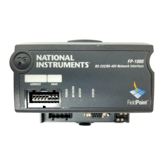
National Instruments FieldPoint FP-1000 Quick Start Manual
Hide thumbs
Also See for FieldPoint FP-1000:
- User manual (74 pages) ,
- Operating instructions manual (12 pages) ,
- Note to users (2 pages)
Advertisement
Quick Links
FP-1000/1001 FieldPoint Quick Start Guide
What You Need to Get Set Up
· Network Module
· Mounting Hardware (DIN rail
or panel mount accessory)
· Terminal Base(s)
· I/O Module(s)
1
Install the Network Module
You can mount the modules on a DIN rail or to a panel.
DIN Rail Mount
A. Unlock rail clip.
· Power Supply
· Accessories: serial cable,
screwdriver
· PC running Windows
· FieldPoint Software CD
Panel Mount
A. Unlock rail clip.
1
Advertisement

Related Manuals for National Instruments FieldPoint FP-1000


Summary of Contents for National Instruments FieldPoint FP-1000
- Page 1 FP-1000/1001 FieldPoint Quick Start Guide What You Need to Get Set Up · Network Module · Power Supply · Mounting Hardware (DIN rail · Accessories: serial cable, or panel mount accessory) screwdriver · Terminal Base(s) · PC running Windows · I/O Module(s) ·...
-
Page 2: Panel Mount
DIN Rail Mount Panel Mount NOTE: Do not use spliced DIN B. Snap panel mount accessory rails. Use only a single DIN rail. (which you can order separately) onto module. B. Hook lip on back of module onto top of DIN rail, press down, and snap into place. - Page 3 Install the Terminal Base(s) CAUTION: Terminal bases must be connected to the network module before applying power to the module. Do not connect or disconnect terminal bases while power is applied to the network module. DIN Rail Mount Panel Mount A.
- Page 4 DIN Rail Mount Panel Mount C. Slide into position and lock the rail D. Repeat for each terminal base, up to clip. Be careful not to bend any pins. nine for each network module in most cases. You can use one or two extender cables (which you can order separately) if the FieldPoint bank is too long for the available space.
-
Page 5: Install The I/O Module(S)
Install the I/O Module(s) It does not matter where you install each I/O module, except for these types of situations: · · · · If you plan to cascade power between any I/O modules using the V and C terminals, those modules should be grouped together. ·... - Page 6 Connect the Network Cables You have several network connection options with the FP-1000 and FP-1001, as shown here. Connecting the FP-1000 to a Computer’s RS-232 Serial Port Use a male-to-female (straight through) cable to connect the computer’s RS- 232 port to the 9-position DSub RS-232 connector on the FP-1000. FP-1000 NOTE: You cannot connect the RS-485 port of the FP-1000 directly to an RS-485 port on the computer.
- Page 7 Connecting the FP-1000 to an FP-1001 You can connect up to 24 FP-1001 RS-485 serial network modules to an FP-1000. Use the RS-485 repeater port of the FP-1000, with the connection shown in this figure. A. Connect the TX outputs of the FP-1001 to the RX inputs of the FP-1000, and the RX inputs of the FP-1001 to the TX outputs of the FP-1000.
- Page 8 RS-485 interface usually provides for biasing resistors, NOTE: The pinout for the RS-485 DB-9 which are required on an connector shown is for National Instruments RS-485 network. You should RS-485 cards. Please refer to the manuals use this biasing feature for better that came with your RS-485 card, as the reliability and noise immunity.
- Page 9 Set the Network Address and Baud Rate If the default values do not work for you, remove the switch cover from the 8-position switch on the front of the FP-1000/1001 to set the network address and baud rate. Address 0 Address 1 Address 2 1 2 3 4 5 6 7 8...
- Page 10 Switch Positions Network Module Switch Positions Network Module Switch Positions Network Module Address (Decimal) Address (Decimal) Address (Decimal) Default 1 2 3 4 5 6 7 8 1 2 3 4 5 6 7 8 1 2 3 4 5 6 7 8 1 2 3 4 5 6 7 8 1 2 3 4 5 6 7 8 1 2 3 4 5 6 7 8...
- Page 11 B. Check/Set the Baud Rate Every module on one serial port of the host computer must have the same baud rate, which must be less than or equal to the computer’s serial port baud rate. The default baud rate for the FP-1000/1001 is 115200, which should provide the fastest performance.
- Page 12 Wire Power to Your FieldPoint System A. Connect 11-30 VDC power supply leads to V and C terminals of the network module. If you want to verify that the power supply is sufficient for the modules and devices, refer to the FieldPoint hardware documents for instructions on calculating power requirements.
- Page 13 CAUTION: Cascading power from neighboring bases or network modules defeats isolation between cascaded modules. Separate Power Supply (Recommended) No External Power Required Cascaded Power (Reduces Isolation) FP-AO-200 FP-RLY-420 FP-TC-120 FP-1000 FP-AI-110 CAUTION: Cascading power defeats isolation. 15 16 V Shades of gray indicate 31 32 C C 17 18 different voltage potentials.
- Page 14 Connect to Field Devices Use each I/O module’s operating instructions, or the diagram under its removable label, to help you connect your field devices. FP-AI-110 To Power Supply Self-Powered Loop-Powered Floating Sensor Sensor Sensor Sensor Channel 0 Channel 7 NOTE: Either the self-powered sensor or power supply should be floating (not tied to earth ground).
- Page 15 Power Up Your FieldPoint System CAUTION: Terminal bases must be connected to the FP-1000/1001 before power is applied to the FP-1000/1001. Plug in each power supply to the FieldPoint bank. You should see the FP-1000/1001 ACCESS and STATUS LEDs flash once and its POWER LED come on and stay on.
- Page 16 FieldPoint software if you have a Windows-based system. A. Close all other applications. If you plan to install National Instruments development software such as Lookout, LabVIEW, or Measurement Studio, install them before you install the FieldPoint software.
- Page 17 Configure the FP-1000/1001 Refer to the FP-1000/1001 User Manual for more information about configuration settings. A. Select Start»Programs»National Instruments FieldPoint»FieldPoint Explorer. B. Click the + to expand the view. C. Right-click the FieldPoint icon and select Add a comm resource to...
- Page 18 D. In the Comm Resource Configuration dialog box, select the port to which your FieldPoint system is connected. Make sure the baud rate matches what the network module is set to use. Click Find Devices. If you have trouble finding devices, try changing the selections in this dialog box to make sure they match your hardware...
- Page 19 If your modules are not listed, check the cable and connections and make sure the modules are all powered on. If you still have problems, refer to your FP-1000/1001 User Manual for troubleshooting information. F. Select an input module and click the start monitoring button view live data.
- Page 20 C. Select the type of channel to show, then select the channel(s) that you want to change. To select more than one channel, uncheck the One channel at a time box. NOTE: Configuration options are module-dependent. The options shown here might not be available for your particular module. Refer to the I/O module operating instructions for details on configuration options.
- Page 21 E. Set the attributes for the selected channel(s) by selecting the attribute and entering the desired value. F. Send commands to the selected channel(s) by choosing a command and value and clicking Send. G. Repeat this procedure for each channel or group of channels you want to configure.
- Page 22 FP-1000/1001 Specifications Installation Terminal wiring ..... . 16-26 AWG copper conductor wire with 7 mm (0.275 in) strip length Torque for screw terminals ... . . 0.5–0.6 Nm (4.4–5.3 in-lbs) Network Network ports FP-1000 .
- Page 23 Safety The FP-1000/1001 meets the requirements of the following standards for safety and electrical equipment for measurement, control, and laboratory use: • EN 61010-1:1993/A2:1995, IEC 61010-1:1990/A2:1995 • UL 3101-1:1993, UL 3111-1:1994, UL 3121:1998 • CAN/CSA c22.2 no. 1010.1:1992/A2:1997 Electromagnetic Compatibility CE, C-Tick and FCC Part 15 (Class A) Compliant Electrical emissions.
- Page 24 Copyright © 1999, 2001 National Instruments Corporation. All rights reserved. CVI™, FieldPoint™, LabVIEW™, Lookout™, Measurement Studio™, and ni.com™ are trademarks of National Instruments Corporation. Product and company names mentioned herein are trademarks or trade names of their respective companies. For patents covering National Instruments products, refer to the appropriate location: Help»Patents in your software,...
Need help?
Do you have a question about the FieldPoint FP-1000 and is the answer not in the manual?
Questions and answers