
Related Manuals for National Instruments MXI


Summary of Contents for National Instruments MXI
- Page 1 Getting Started with Your PCI-Based MXI-2 Interface for Windows 2000/NT/Me/98 PCI-Based MXI-2 Interfaces for Windows 2000/NT/Me/98 September 2001 Edition Part Number 323193A-01...
- Page 2 Sweden 08 587 895 00, Switzerland 056 200 51 51, Taiwan 02 2528 7227, United Kingdom 01635 523545 For further support information, see the Technical Support Resources appendix. To comment on the documentation, send e-mail to techpubs@ni.com. Copyright © 1997, 2001 National Instruments Corporation. All rights reserved.
- Page 3 The reader should consult National Instruments if errors are suspected. In no event shall National Instruments be liable for any damages arising out of or related to this document or the information contained in it.
- Page 4 Classification requirements are the same for the Federal Communications Commission (FCC) and the Canadian Department of Communications (DOC). Changes or modifications not expressly approved by National Instruments could void the user’s authority to operate the equipment under the FCC Rules.
- Page 5 Canadian Department of Communications This Class B digital apparatus meets all requirements of the Canadian Interference-Causing Equipment Regulations. Cet appareil numérique de la classe B respecte toutes les exigences du Règlement sur le matériel brouilleur du Canada. Compliance to EU Directives Readers in the European Union (EU) must refer to the Manufacturer’s Declaration of Conformity (DoC) for information** pertaining to the CE Mark compliance scheme.
-
Page 6: Table Of Contents
Related Documentation....................xii Chapter 1 Introduction How to Use This Manual ....................1-1 What You Need to Get Started ..................1-2 PCI-Based MXI-2 Interface Kit Overview ..............1-2 Hardware Description ....................1-3 VME Users ......................1-4 Software Description .....................1-4 National Instruments Application Software ............1-5 Chapter 2 Setup Configuring the Hardware .....................2-1... - Page 7 NI-VXI API Notes ..................3-8 Compiler Symbols ................3-8 Compatibility Layer Options ............3-9 Debugging ........................3-10 Appendix A Default Settings Appendix B Common Questions Appendix C Technical Support Resources Glossary Index PCI-Based MXI-2 Interfaces for Windows 2000/NT/Me/98 viii ni.com...
-
Page 8: About This Manual
Windows 2000/NT/Me/98. This manual is meant to be used with the MXI-2 Configuration Reference Manual. Your kit contains either a VXI-MXI-2 or VME-MXI-2, which plugs into your VXI or VME mainframe and links your computer to the VXIbus or VMEbus, respectively. The kit also contains either a PCI-MXI-2 or a PXI-8320 interface board, which links your PCI-based or PXI/CompactPCI computer to the MXIbus. -
Page 9: How To Use This Documentation Set
Reference NI Spy, VISAIC This getting started manual contains an overview of the MXI-2 hardware and the NI-VXI software, guides you through setting up your kit, and helps you get started with application development. You can also use this manual as a reference for the hardware and software default settings and to find the answers for commonly asked questions. -
Page 10: Conventions
This font also emphasizes lines of code that are different from the other examples. Italic text in this font denotes text that is a placeholder for a word or value monospace italic that you must supply. © National Instruments Corporation PCI-Based MXI-2 Interfaces for Windows 2000/NT/Me/98... -
Page 11: Related Documentation
Multisystem Extension Interface Bus Specification, Version 2.0, National Instruments Corporation • PCI Local Bus Specification, Revision 2.1, PCI Special Interest Group • PXI Specification, Revision 2.0, National Instruments Corporation • VME-MXI-2 User Manual, National Instruments Corporation • VXI-MXI-2 User Manual, National Instruments Corporation •... -
Page 12: Introduction
Introduction This chapter describes your MXI-2 interface kit, lists what you need to get started, and includes a brief description of the hardware and software. This manual uses the term VXI/VME-MXI-2 when information applies to either the VXI-MXI-2 or the VME-MXI-2. This manual also uses the term Windows 2000/NT/Me/98 when information applies to all supported Windows operating systems. -
Page 13: What You Need To Get Started
VME-PCI8000 interface, or a PXI/CompactPCI chassis equipped with a VME-PXI8000, can function as a VMEbus master and/or slave device. The MXI-2 interface kit makes your computer or chassis behave as if it were plugged directly into the VXI/VME backplane as an embedded CPU VXI/VME module. -
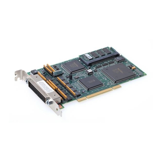
Page 14: Hardware Description
VXI-MXI-2. By connecting to the PCI-MXI-2 or PXI-8320 board, the PCI bus or the PXI/CompactPCI bus is linked to the VMEbus. The VME-MXI-2 can automatically determine if it is located in the first slot of a VMEbus chassis and if it is the MXIbus System Controller. -
Page 15: Vme Users
VXI devices, including the VXI-MXI-2. When used with a VME-MXI-2, Resman configures the VME-MXI-2 to allow the PCI-MXI-2 or PXI-8320 to access devices in the VME chassis. Resman does not configure VME devices. The VME specification does not include the initialization and configuration procedures that the VXI specification requires. -
Page 16: National Instruments Application Software
National Instruments Application Software In addition to the NI-VXI software, you can use the National Instruments LabVIEW and Measurement Studio application programs and instrument drivers to ease your programming tasks. These standardized programs match the modular virtual instrument capability of VXI and can reduce your VXI/VME software development time. - Page 17 If you want to use either of these application programs, install them after the NI-VXI software installation. Both LabVIEW and Measurement Studio integrate well with PCI-based MXI-2 products. You also get hundreds of complete instrument drivers, which are modular, source-code programs that handle the communication with your instrument to speed your application development.
-
Page 18: Setup
This section contains basic information about configuring your MXI-2 hardware. Install the NI-VXI software for Windows before installing the VXI hardware. Note The default settings for your MXI-2 hardware are acceptable for most applications. Refer to Appendix A, Default Settings, for a complete listing of the hardware and software default settings. -
Page 19: Installing Your Mainframe Extender
Your VXI or VME chassis should be plugged in but powered off. Install the VXI-MXI-2 or VXI-MXI-2/B in the first slot of a VXI chassis, or install the VME-MXI-2 in the first slot of a VME chassis. -
Page 20: Connecting The Mxi-2 Cable Properly
Connect This End To Device Closest To MXIbus Controller In This Daisy Chain is attached securely to the PCI-MXI-2 or PXI-8320. The cable must be connected in this manner so that the MXI board can correctly detect whether it should be the system controller on the MXIbus. -
Page 21: Completing The Software Installation
The NI-VXI driver is loaded at this time. If you backed up the manufacturer and model name files, restore them to the TBL subdirectory of your NI-VXI directory before running MAX. PCI-Based MXI-2 Interfaces for Windows 2000/NT/Me/98 ni.com... -
Page 22: Verifying Your System Configuration
MAX to configure Resman to run automatically at every computer startup. After you run Resman, you are ready to use MAX to interactively configure the National Instruments hardware in your system. Use the right-click help for information about the various configuration options. -
Page 23: Developing Your Application
Before you develop your application, it is important to understand the difference between NI-VXI, NI-VISA, and similar terms: • NI-VXI is the software package that ships with National Instruments VXI and VME controllers. NI-VXI includes Measurement & Automation Explorer (MAX), NI-VISA, NI Spy, Resource Manager (Resman), VXI device drivers, and other utilities for configuring and controlling your VXI or VME system. -
Page 24: Configuration
Each component assists you with one of four development steps: configuration, device interaction, programming, and debugging. You can access the utilities, help files, and release notes through the Windows Start menu by opening the National Instruments»VXI or National Instruments»VISA program groups. Configuration The configuration utilities in your software kit are Resman and MAX. - Page 25 For more information about MAX, refer to its online help by selecting the Help»Help Topics menu. © National Instruments Corporation PCI-Based MXI-2 Interfaces for Windows 2000/NT/Me/98...
-
Page 26: Device Interaction
You can launch VISAIC (or VIC) from the Tools menu in MAX or from the VISA or VXI subgroups in Start»Programs»National Instruments. Try the following in VISAIC: In the tree view, navigate using your mouse to the VISA resource for your controller—probably VXI0::0::INSTR,... - Page 27 MAX view of your VXI system. This way, you can verify that your VXI controller can access each device in your VXI system successfully. © National Instruments Corporation PCI-Based MXI-2 Interfaces for Windows 2000/NT/Me/98...
-
Page 28: Programming For Vxi
NI-VXI API Notes section later in this chapter. NI-VISA is the National Instruments implementation of the VISA API as the VXIplug&play standard defines. It provides a common interface to many types of instruments (such as VXI, GPIB, PXI, Serial, TCP/IP, etc.) and therefore is especially useful in situations where you are using multiple types of instruments. -
Page 29: Optimizing Large Vxibus Transfers
Make sure your buffers are 32-bit aligned. • Transfer 32-bit data whenever possible. • Use VXI block access privileges to significantly improve performance to devices that are capable of accepting block transfers. © National Instruments Corporation PCI-Based MXI-2 Interfaces for Windows 2000/NT/Me/98... -
Page 30: Shared Memory
In the Hardware Configuration settings for your controller in MAX, you can share memory on your computer or from DRAM added to the PCI-MXI-2 or VXI-MXI-2 if you have any installed. Right-click on any setting or consult the MAX online help for more information. You can... -
Page 31: Compatibility Layer Options
Select Tools»NI-VXI»VXI Options. Set Prioritized Signal LA to the logical address of the device that generates the events. This prevents possible loss of events from that device. © National Instruments Corporation PCI-Based MXI-2 Interfaces for Windows 2000/NT/Me/98... -
Page 32: Debugging
NI Spy and VISAIC are useful utilities for identifying the causes of problems in your application. NI Spy tracks the calls your application makes to National Instruments programming interfaces, including NI-VISA, NI-VXI, and NI-488. NI Spy highlights functions that return errors, so during development you can quickly spot which functions failed during a program’s execution. - Page 33 VISAIC, discussed above in the Device Interaction section of this chapter, is an excellent platform for quickly testing instruments and learning how to communicate with them. Figure 3-5. VISAIC © National Instruments Corporation 3-11 PCI-Based MXI-2 Interfaces for Windows 2000/NT/Me/98...
-
Page 34: Appendix A Default Settings
Use the MXI-2 Configuration Reference Manual for your hardware reference and the MAX online help for your software reference. - Page 35 DRAM SODIMM installed Per customer order MAX Settings Table A-3. Device Tab Default Settings Editor Field Default Setting Logical address Device class Message-based Size of Servant area Number of handlers Number of interrupters PCI-Based MXI-2 Interfaces for Windows 2000/NT/Me/98 ni.com...
- Page 36 Upper half window byte swapping Disabled Upper half window memory selection System memory Map upper and lower halves at same Disabled PCI address Table A-5. MXI-2 Bus Tab Default Settings Editor Field Default Setting Bus timeout 1 ms System controller Auto-detect...
- Page 37 Expansion ROM Enabled VXI/VME-MXI-2 This section summarizes the hardware and software default settings for the VXI-MXI-2, VXI-MXI-2/B, and VME-MXI-2. Hardware Settings Table A-7. VXI-MXI-2 Hardware Default Settings Hardware Component Default Setting Logical address (U43) VXIbus Slot 0/Non-Slot 0 (W2) Automatic detection...
- Page 38 Appendix A Default Settings Table A-7. VXI-MXI-2 Hardware Default Settings (Continued) Hardware Component Default Setting MXIbus termination Automatic MXIbus (U35 switches 1 and 2) termination: switch 2 set to NO; switch 1 ignored Configuration EEPROM User-modifiable; factory (U35 switches 3 and 4)
- Page 39 Appendix A Default Settings Table A-8. VXI-MXI-2/B Hardware Default Settings (Continued) Hardware Component Default Setting MXIbus termination Automatic MXIbus (U21 switches 3 and 4) termination: switch 3 set to OFF; switch 4 ignored Configuration EEPROM User-modifiable; factory (U21 switches 1 and 2)
- Page 40 Table A-11. VXI/VME Bus Tab Default Settings Editor Field Default Setting 125 µs Bus timeout value Slot 0 configuration Auto-detect Auto retry Disabled Transfer limit Arbiter type Priority Fair requester Enabled Arbiter timeout Enabled Request level © National Instruments Corporation PCI-Based MXI-2 Interfaces for Windows 2000/NT/Me/98...
- Page 41 Appendix A Default Settings Table A-12. MXI-2 Bus Tab Default Settings Editor Field Default Setting System controller Auto-detect Bus timeout value 1 ms MXI-2 auto retry Disabled MXI transfer limit Unlimited MXI fair requester Disabled Perform parity checking Enabled MXI-2 CLK10 signal direction...
-
Page 42: Appendix B Common Questions
Common Questions This appendix addresses common questions you may have about using the NI-VXI/NI-VISA software on the PCI-MXI-2 or PXI-8320 platform. What are some of the differences between the old utilities and the current ones? The old utility components are as follows: •... - Page 43 (GPIB, VXI, and Serial) that it finds in your system. Right-click on an individual device in the configuration tree to see its properties. You can further configure National Instruments devices by selecting the Hardware Configuration option. This includes National Instruments DAQ products, which means you can configure these devices from MAX without running the DAQ Configuration Utility.
- Page 44 Resman runs. Power cycling the chassis reboots the embedded PC, causing Resman to run again. With the PCI-MXI-2 or PXI-8320, you may need to run the Resman utility if you boot your computer before turning on your VXI chassis or if you power-cycle your VXI chassis while the external PC remains on.
- Page 45 How can I determine the serial number and hardware revision of the MXI-2 boards? Run MAX and right-click on the name of the MXI-2 board in the configuration tree. Select Hardware Configuration, and the dialog box for the MXI-2 board is displayed. The title bar includes the serial number and hardware revision of the board.
- Page 46 The fastest method for testing the system is to run Resman. This program attempts to access memory in the upper A16 address space of each device in the system. If Resman does not report any problems, the VXI/MXI communication system is operational.
- Page 47 Check for bent or broken pins on the MXI-2 connectors. If you are using a VME-MXI-2 in the first slot of a VMEbus chassis, the chassis may be causing problems with the First Slot Detection circuit on the VME-MXI-2.
- Page 48 The MXI LED indicates that the VXI-MXI-2 or VME-MXI-2 is acting as a slave to another device on the MXIbus, such as when the PCI-MXI-2 or PXI-8320 communicates with either the VXI-MXI-2 or VME-MXI-2 or with another device in the chassis.
- Page 49 NI-VXI uses the driver window to perform high-level functions such as viIn/Out() VXIin/out() to access registers on the MXI-2 boards in the system. The user window is reserved for low-level function calls, such as viPeek Poke() , and .
- Page 50 Technical Support Resources Web Support National Instruments Web support is your first stop for help in solving installation, configuration, and application problems and questions. Online problem-solving and diagnostic resources include frequently asked questions, knowledge bases, product-specific troubleshooting wizards, manuals, drivers, software updates, and more. Web support is available through the Technical Support section of ni.com...
- Page 51 Appendix C Technical Support Resources Worldwide Support National Instruments has offices located around the world to help address your support needs. You can access our branch office Web sites from the Worldwide Offices section of . Branch office Web sites provide ni.com...
- Page 52 In VISA, it identifies a resource. address modifier One of six signals in the VMEbus specification used by VMEbus masters to indicate the address space in which a data transfer is to take place © National Instruments Corporation PCI-Based MXI-2 Interfaces for Windows 2000/NT/Me/98...
- Page 53 In VME, the data transfer may have no more than 256 elements; MXI does not have this restriction. BTO unit Bus Timeout Unit;...
- Page 54 Data Transfer Bus DTB; one of four buses on the VMEbus backplane. The DTB is used by a bus master to transfer binary data between itself and a slave device. © National Instruments Corporation PCI-Based MXI-2 Interfaces for Windows 2000/NT/Me/98...
- Page 55 DRAM Dynamic RAM (Random Access Memory); storage that the computer must refresh at frequent intervals driver window A region of PCI address space that is decoded by the PCI-MXI-2 or PXI-8320 for use by the NI-VXI software Data Transfer Bus.
- Page 56 Kilobytes of memory logical address An 8-bit number that uniquely identifies each VXIbus device in a system. It defines the A16 register address of a device, and indicates Commander and Servant relationships. © National Instruments Corporation PCI-Based MXI-2 Interfaces for Windows 2000/NT/Me/98...
- Page 57 MXI-2 The second generation of the National Instruments MXIbus product line. MXI-2 expands the number of signals on a standard MXIbus cable by including VXI triggers, all VXI interrupts, CLK10, SYSFAIL*, SYSRESET*, and ACFAIL*. MXI-2 also defines higher-performance data transfer protocols.
- Page 58 Slot 0. Installing such a device into Slot 0 can damage the device, the VXIbus backplane, or both. Onboard RAM The optional RAM installed into the SIMM slots of the MXI-2 board Peripheral Component Interconnect. The PCI bus is a high-performance 32-bit or 64-bit bus with multiplexed address and data lines.
- Page 59 A VMEbus signal that is used by a device to indicate a system reset or power-up condition System RAM RAM installed on your personal computer and used by the operating system, as contrasted with onboard RAM, which is installed on the MXI-2 board PCI-Based MXI-2 Interfaces for Windows 2000/NT/Me/98 ni.com...
- Page 60 Either TTL or ECL lines used for intermodule timing Transistor-Transistor Logic user window A region of PCI address space reserved by the PCI-MXI-2 or PXI-8320 for use via the NI-VXI low-level function calls. MapVXIAddress() use this address space to allocate regions for use by the...
- Page 61 A mechanism that signifies that a device will immediately give a successful acknowledge to a write transfer and place the transfer in a local buffer. The device can then independently complete the write cycle to the destination. PCI-Based MXI-2 Interfaces for Windows 2000/NT/Me/98 G-10 ni.com...
- Page 62 2-1 configuring more than one device as debugging your application, 3-10 system controller (caution), 2-2 default settings connecting MXI-2 cable, 2-3 PCI-MXI-2/PXI-8320 hardware settings, A-1 MAX settings, A-2 © National Instruments Corporation PCI-Based MXI-2 Interfaces for Windows 2000/NT/Me/98...
- Page 63 2-5 installing, 3-6 overview, 3-1 programming notes, 3-8 NI-VXI compatibility layer, 3-1 LabWindows/CVI, 1-6 NI-VXI software LEDs on front of VXI-MXI-2 or determining which version is VME-MXI-2, B-7 installed, B-4 logical address in multiple-mainframe example programs (table), 3-7 system, B-8...
- Page 64 VXIinit, B-1, B-2 system controller (caution), 2-2 VXIplug&play specifications, 1-5 optional MXIbus system controller, 1-3 VXItedit, B-1 system integration, by National Instruments, C-1 system requirements, 1-2 © National Instruments Corporation PCI-Based MXI-2 Interfaces for Windows 2000/NT/Me/98...
- Page 65 Web support from National Instruments, C-1 WIN95/GWIN95 framework, 1-5 WINNT/GWINNT framework, 1-5 worldwide technical support, C-2...
Need help?
Do you have a question about the MXI and is the answer not in the manual?
Questions and answers