
Related Manuals for Skov BF 55


Summary of Contents for Skov BF 55
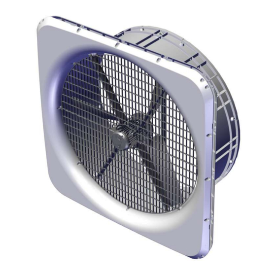
- Page 1 BF 55 Wall Fan Without Cone and Shutter Technical User Guide S604449A • 2023-10-16...
- Page 3 Note • All rights belong to SKOV A/S. No part of this manual may be reproduced in any manner whatsoever without the expressed written permission of SKOV A/S in each case.
-
Page 4: Table Of Contents
BF 55 Wall Fan 1 Product description ............................ 6 2 Product survey ............................... 7 3 Mounting guide............................... 8 Recommended tools........................ 8 Placement of wall fan ...................... 10 Preparing hole in wall...................... 10 3.3.1 Necessary space for wall fan with LPC motor controller............ 10 3.3.2... - Page 5 Recycling/Disposal ........................ 36 6 Trouble shooting instructions ........................ 37 7 Technical data .............................. 39 BF 55 LPC HF 400V3........................ 39 7.1.1 ErP/Ecodesign BF 55 LPC HF 400V3 .................. 41 Dimensioned sketch ........................ 42 7.2.1 Wall fan with LPC motor controller..................... 42 7.2.2 LPC motor controller ........................
-
Page 6: Product Description
BF 55 Wall Fan 1 Product description BF 55 wall fan is a flange-mounted corrosion-free fan. BF 55 is specially designed for harsh livestock house environments. This applies to both climatic and electrical influences. Technical User Guide... -
Page 7: Product Survey
BF 55 Wall Fan 2 Product survey For every 100 pcs. BF 55 wall fans 1 extra BF 55 mounting parts and documentation (S560425A) are supplied. For every 101-200 pcs., 2 extra BF 55 mounting parts and documentation (S560425A) etc. are sup- plied. -
Page 8: Mounting Guide
BF 55 Wall Fan 3 Mounting guide Check that the parts ordered are present and undamaged before starting work. Please read through the entire guide before starting assembly and fitting. If the wall fan is installed in areas with risk of load of snow or ice/snow slide, precautions must be made to avoid damage to the wall fan. - Page 9 BF 55 Wall Fan Item Description Foam gun Ladder Jigsaw Socket wrench set Water pump (multi-grip) pliers Spirit level Try square 2 men Technical User Guide...
-
Page 10: Placement Of Wall Fan
BF 55 Wall Fan 3.2 Placement of wall fan The wall fan must be placed in the livestock house according to the drawing supplied. Contact SKOV A/S if ma- jor changes are made. Check that all wall fans can be placed freely in relation to other housing equipment upon agreement with the client. -
Page 11: Measurements For Round Hole
BF 55 Wall Fan 3.3.2 Measurements for round hole The dimensions below are given in mm . Recommended measurements for individual mounting of wall fan. (A) Minimum distance is 550 mm, when mounting the LPC motor controller above wall fan. Without LPC motor controller, the distance can be reduced to a minimum of 275 mm. -
Page 12: Measure And Saw Out The Holes
BF 55 Wall Fan 3.4 Measure and saw out the holes Remember always to use a spirit level. Drill 10 mm holes all the way through the wall. Cut the holes. Technical User Guide... -
Page 13: Press The Front Panel Together
BF 55 Wall Fan 3.5 Press the front panel together Lay the 4 front panels on the floor. Press the front panels together in all 4 corners. 3.6 Mounting ventilation duct on front panel Mount the 4 ventilation ducts on the front panel. - Page 14 BF 55 Wall Fan Assemble the front panel and the ventilation duct using: • 20 x M6 screw with flange • 20 x ø6 washers • 20 x M6 self-locking nut Assemble the front panel and the ventilation duct using: •...
-
Page 15: Mounting Center Pillar
BF 55 Wall Fan 3.7 Mounting center pillar Mount top and bottom brackets on the center pillar using: • 2 x M6x50 screw • 4 x ø6.4 washers • 2 x bushings ø6/ø10x39.6 • 2 x M6 self-locking nut 3.8 Mounting the center pillar on the ventilation duct Deploy the top and bottom brackets in the ventilation duct. -
Page 16: Mounting In Wall
BF 55 Wall Fan 3.9 Mounting in wall Center the wall fan in the hole, use wedges at the bot- tom. Use the holes in the wall wall to mark out holes in the wall. Mounting in a sandwich wall: Drill 3 mm holes in the wall. -
Page 17: Mounting The Top Motor Suspension
BF 55 Wall Fan 3.10 Mounting the top motor suspension Mount the 4 motor suspensions onto the motor using: • 8 x M8x20 screw • 8 x ø8 locking washers • 8 x ø8 washers • 8 x bushings ø8/ø12x7.7... -
Page 18: Mounting Impeller
BF 55 Wall Fan 3.11 Mounting impeller The 3 blades delivered together must NOT be mixed with other blades. 1, 2, 3 and I, II, III are printed on the rear hub. 1, 2, 3 and I, II, III are printed on the fan blade pitch adapter. - Page 19 BF 55 Wall Fan Mount the front hub on the rear hub using: • 6 x M6x25 • 12 x ø6.4/ø18x1.2 washers • 6 x M6 self-locking nut It should be tightened at 10 Nm. The grooves on the fan blade and the grooves on the axle must be in line with each other.
-
Page 20: Mounting The Motor In The Fan Housing
BF 55 Wall Fan 3.12 Mounting the motor in the fan housing Mount the motor with motor suspensions in the fan hous- ing using: • 4 x M6x80 screw • 8 x ø6 washers • 4 x bushings ø6/ø10x69.6 • 4 x M6 self-locking nut Make sure the blades can turn freely in the ventilation duct. -
Page 21: Cabling From Fan Motor
BF 55 Wall Fan 3.13 Cabling from fan motor (B) Drill a 13 mm hole for the fan motor cables at center mark. (C) Select where to exit the cables at the side or at the bottom and drill a 13 mm hole for the fan motor cable a at center mark. -
Page 22: Foaming And Pointing Of The Outside
BF 55 Wall Fan 3.14 Foaming and pointing of the outside SKOV A/S recommends: • For foaming Single-component polyurethane foam or similar. Check how much the foam ex- pands before foaming. • For pointing Berner Fix MS polymer joint sealer gray 600 ml. -
Page 23: Pointing Of The Inside
BF 55 Wall Fan 3.15 Pointing of the inside SKOV A/S anbefaler -polymer joint sealer gray 600 ml for pointinging. Berner Fix MS Apply a sealing edge between the wall fan and the wall. Apply a sealing next to all places where the cables have been led through. -
Page 24: Mounting The Wall Cover Outside
BF 55 Wall Fan 3.16 Mounting the wall cover outside Place the top cover. Mount the 2 side covers by lifting the top cover and click- ing together. Then mount the bottom cover on the side cover. Mount the covers using: •... -
Page 25: Attaching The Warning Label
BF 55 Wall Fan 3.17 Attaching the warning label Attach the warning label on the inside of the fan duct. Attach the warning label on the inside of the fan duct. Technical User Guide... -
Page 26: Mounting The Inside Safety Net
BF 55 Wall Fan 3.18 Mounting the inside safety net Rotate one net over the other so that the hooks grip each other. Assemble the inside safety net at the motor using: • 2 x PT 6x20 screw Mount the inside safety net on the duct using: •... -
Page 27: Installation Guide
In the case of retrofitting fans in an existing house, regardless of ON/OFF fans, LPC fans or frequency convert- ers SKOV recommends that a local expert is involved in checking the electrical installations. The focus should be on cable dimensions, overload protections, local transformers, etc. It is of outmost importance to take the fan specifications into account and, at the same time, ensure that local requirements are fulfilled. -
Page 28: Cabeling And Placement Of Lpc Motor Controller
BF 55 Wall Fan 4.1.4 Cabeling and placement of LPC motor controller Motor controller must not be built-in or covered and must be mounted on a solid, level surface. In order to uphold protection classifications, ensure ac- cess of cables and cooling of the motor controller, the distances to the surroundings of 150 mm must be met. -
Page 29: Connection In The Lpc Motor Controller/Frequency Converter
BF 55 Wall Fan 4.2 Connection in the LPC motor controller/frequency converter Motor connection terminals (U, V, W, PE) Connection terminals for braking resistor (not used) Connector for optional module Terminal block for programming interface RJ12 programming connector (2 x slave / 1 x master) -
Page 30: Terminals For Power Supply
BF 55 Wall Fan 4.2.1 Terminals for power supply Power supply 3 x 400 V 4.2.2 Terminals for supply of the fan motor Remember to strip the cable so that the protective shield from the fan can be connected to the motor controller during mounting under the rail. -
Page 31: Signal Terminals
BF 55 Wall Fan 4.2.3 Signal terminals Not in use Not in use Ground Not in use Signal from controller Ground 10-0 V = open 0-10 V = GND (Short-circuit connection between terminal 7 and GND) Stop = open Start = GND (Short-circuit connection between terminal 8 and... -
Page 32: Led Indication On The Motor Controller/Frequency Converter
BF 55 Wall Fan 4.3 LED indication on the motor controller/frequency converter The motor controller/frequency converter is equipped with a two-color LED for indication of different operating modes. LED is located on the underside next to the cable glands. • Constantly green when mains voltage is connected. -
Page 33: Connection To Kick On Timer
BF 55 Wall Fan 4.5 Connection to Kick ON timer 4.5.1 IN/OUT timing LED indication OK = slow flashing (1 time/second) Kick ON timer active = constant light Error = fast flashing (10 times/second) 20 sec. 25 sec. 30 sec. -
Page 34: Mounting Of Kick On Timer On Din Rail
BF 55 Wall Fan 4.5.2 Mounting of Kick ON timer on DIN rail 80.5 mm DIN 35 94 mm 88.8 mm Kick ON Timer TX10 M3x8 mm 4.6 General information about circuit diagrams Symbols are in accordance with the IEC/EN 60617 standard. -
Page 35: Cable Plans And Circuit Diagrams
BF 55 Wall Fan 4.7 Cable plans and circuit diagrams 4.7.1 Cable plan Controller BF 55 LPC motor controller Connection box Power supply isolator 4.7.2 Circuit diagram Example of terminal number For correct connection see the setup menu Show connection in the controller... -
Page 36: Maintenance Instructions
When washing the inside of the ducts, fan blades must stand still. Remember that fans do not stand high-pressure cleaning. If the inside of the duct needs to be cleaned extra thoroughly SKOV A/S recommends washing from above. When washing the fan, the fan must run around. -
Page 37: Trouble Shooting Instructions
BF 55 Wall Fan 6 Trouble shooting instructions Remember to shut the fan off at the power supply isolator prior to troubleshooting. Troubleshooting fan motor Fault symptom Error Solution Faulty mounting. Check in accordance with the docu- ment. Retighten if required. - Page 38 BF 55 Wall Fan Troubleshooting LPC motor controller Fault symptom Status LED Error Solution Flashes red* Internal temperature of the LPC Check the mounting of LPC motor motor controller too high controller, see section Cabling to con- Reduced perfor- (>95°C).
-
Page 39: Technical Data
BF 55 Wall Fan 7 Technical data 7.1 BF 55 LPC HF 400V3 S435463A / S435475A BF 55 LPC HF 400V3 Electrical V AC 400 ± 10 % Rated voltage V AC 300 – 485 Operating voltage For supply voltages below the rated voltage range, a reduction of the fan’s RPM may occur depending on the load and ambient... - Page 40 BF 55 Wall Fan S435463A / S435475A BF 55 LPC HF 400V3 % RH 10 - 95 Ambient humidity, operation Motor controller: IP 65. Fan motor: IP 65 Protection class dB (A) *Fan noise (sound pressure), outside (2 m, 45 degrees)
-
Page 41: Erp/Ecodesign Bf 55 Lpc Hf 400V3
BF 55 Wall Fan 7.1.1 ErP/Ecodesign BF 55 LPC HF 400V3 Fan type ErP 2015 (40) Ecodesign 57.4 Efficiency classification 53.1 Efficiency (η) Measurement setup Static Fan efficiency VSD required 2023 Year of production SKOV A/S Name of manufacturer S435463A / S435475A Item number 2108.6... -
Page 42: Dimensioned Sketch
BF 55 Wall Fan 7.2 Dimensioned sketch 7.2.1 Wall fan with LPC motor controller BF 55 with LPC motor controller 7.2.2 LPC motor controller LPC motor controller 3x400 V Technical User Guide... - Page 44 SKOV A/S • Hedelund 4 • Glyngøre • DK-7870 Roslev Tel. +45 72 17 55 55 • www.skov.com • E-mail: skov@skov.dk...
Need help?
Do you have a question about the BF 55 and is the answer not in the manual?
Questions and answers
shutter is not closing 100%