Table of Contents
Advertisement
Advertisement
Table of Contents

Related Manuals for Skov BF 50


Summary of Contents for Skov BF 50
- Page 1 BF 50 Wall Fans Technical User Guide English For other language variants of this document we refer to: Español Para otras variantes del idioma de este documento, visite: Français Pour les versions dans d'autres langues de ce document veuillez consulter: http://docs.skov.com/1241...
- Page 3 The date of change appears from the front and back pages. Note • All rights belong to SKOV A/S. No part of this manual may be reproduced in any manner whatsoever without the expressed written permission of SKOV A/S in each case.
-
Page 4: Table Of Contents
Recommended tools........................ 16 Placement of BF 50 ......................... 18 Preparing hole in wall...................... 18 3.3.1 Necessary space for BF 50 without LPC motor controller ............ 18 3.3.2 Necessary space for BF 50 with LPC motor controller .............. 18 3.3.3 Necessary space for BF 50 without cone .................. 19 3.3.4... - Page 5 4.1.19.2 Terminals in LPC 3x400 V fan .................... 66 4.1.19.3 Circuit diagram........................... 67 4.1.20 BF 50 LPC 3x400 V with actuator – stepless (435409/435382) .......... 68 4.1.20.1 Cable plan.......................... 68 4.1.20.2 Terminals in LPC 3x400 V fan .................... 68 4.1.20.3 Circuit diagram...........................
- Page 6 Terminals in ON/OFF 3x400 V fan..................... 84 4.1.28.3 Circuit diagram........................... 85 4.1.29 BF 50 AIR ON/OFF 3x400 V with thermal cutout (435441) ............ 86 4.1.29.1 Cable plan.......................... 86 4.1.29.2 Terminals in ON/OFF 3x400 V fan with thermal cutout ............. 86 4.1.29.3...
- Page 7 BF 50 Wall Fans LPC motor controller ...................... 120 Light trap .......................... 121 Outside safety net........................ 121 Technical User Guide...
-
Page 8: Product Description
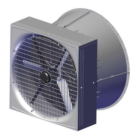
The fan is available in several different versions focusing on low power consumption, as well as standard ver- sions. BF 50 can be mounted using a cone for optimal air output and reduced power consumption. BF 50 is specially designed for harsh livestock house environments. This applies to both climatic and electrical influences. Technical User Guide... -
Page 9: Product Survey
BF 50 Wall Fans 2 Product survey Technical User Guide... -
Page 10: Bf 50 Wall Fans
BF 50 Wall Fans 2.1 BF 50 wall fans 2.1.1 Type key BF 50 ON/OFF EL HF 400V3 50Hz 1.5hp TH Fan name Blue fan Fan size Impeller diameter in inches” Fan type AC fan ON/OFF LPC fan Shutter type... - Page 11 BF 50 Wall Fans 435405 BF 50 LPC ON/OFF HF 400V3 50/60Hz 435408 BF 50 LPC ON/OFF LE 400V3 50/60Hz Fan control method - variable ON/OFF. 435409 BF 50 LPC VAR HF 400V3 50/60Hz 435382 BF 50 LPC VAR LE 400V3 50/60Hz Fan control method - stepless.
- Page 12 BF 50 Wall Fans 435388 BF 50 ON/OFF EL 400V3 1.5Hp 50Hz 435404 BF 50 ON/OFF EL 400V3 1.5Hp 50Hz TH Fan control method - ON/OFF Safety net outside must be mounted to comply with CE marking, in coun- tries where this is required.
-
Page 13: Accessories
2.2 Accessories 435397 BF 50 safety net outside wo/cone, A2 435398 BF 50 safety net outside wo/cone, galv The outside safety net is used on BF 50 without cone where extra safety is required. Supplied with mounting parts. One for each fan. - Page 14 Supplied with mounting parts. 1 per wall fan. 435998 BF 50 insulation plate The insulation plate is used for mounting on a BF 50 wall fan where extra insulation is necessary. Used to avoid problems with condensation and cold air down draft, espe- cially during the winter.
- Page 15 BF 50 Wall Fans 435156 50" light trap brown out Used if dimming is required in the livestock house. Light reduction factor 175.000:1. The light trap reduces the air output of the fan without cone by approx. 15 % at 0-70 Pa pressure difference.
-
Page 16: Mounting Guide
Check that the parts ordered are present and undamaged before starting work. Please read through the entire guide before starting assembly and fitting. If the BF 50 is installed in areas with risk of ice/snow slide, precautions must be made to avoid damage to the BF 50. - Page 17 BF 50 Wall Fans Item Description Foam gun Ladder Jigsaw Socket wrench set Spirit level Try square Technical User Guide...
-
Page 18: Placement Of Bf 50
Check that all BF 50 can be placed freely in relation to other housing equipment upon agreement with the client. Place the insulation of the brickwork all the way in against the BF 50 and all the way round (as in other building constructions). -
Page 19: Necessary Space For Bf 50 Without Cone
Recommended installation height from floor is mini- mum (E) in order to ensure space for dung removal. 3.3.4 Necessary space for BF 50 wth air shutter Air shutter inside. There must be a minimum of (A) space inside the live- stock house for the wall fan. -
Page 20: Measurements For Square Hole In Wall
Recommended measurements for individual mounting of BF 50 wall fan. (A) Minimum distance is 550 mm, when mounting the LPC motor controller above BF 50. (B) Minimum distance is 300 mm, when mounting the LPC motor controller between BF 50. -
Page 21: Measurements For Square Hole In Wall With Cone
Recommended measurements for individual mounting of BF 50 wall fan with mounted cone. (A) Minimum distance is 550 mm, when mounting the LPC motor controller above BF 50. (B) Minimum distance is 300 mm, when mounting the LPC motor controller between BF 50. -
Page 22: Measure And Saw Out The Holes
BF 50 Wall Fans 3.4 Measure and saw out the holes Remember to always use a spirit level. Drill 10 mm holes all the way through the wall. Cut the holes. Technical User Guide... -
Page 23: Drainage Holes
Please note that the yellow blanking plug must be at the top. Black If parts of BF 50 are outside the wall, on the outside, it is recommended to drill 4 pcs. 5 mm drain holes in the bottom on the four markings. -
Page 24: Mounting In Wall
Lead the cables into the livestock house. Make sure that there is free space for cables. Measure from the top of BF 50 down (A) make a hole in the wall for the cables as the bending radius of the fan cables is 50 mm. -
Page 25: Mounting With Four Brackets
BF 50 Wall Fans 3.6.1 Mounting with four brackets Mount 2 brackets (not supplied) in the bottom of BF 50 to fit the wall thickness. Place BF 50 in the wall. Use wedges to center BF 50 in the hole. -
Page 26: Mounting Of Four Angle Bars
BF 50 Wall Fans 3.6.2 Mounting of four angle bars Mount the 4 angle bars (not supplied) on BF 50 to fit the wall thickness. Place BF 50 in the wall. Technical User Guide... -
Page 27: Mounting In Wooden Frame
BF 50 Wall Fans 3.6.3 Mounting in wooden frame Mount the wooden frame with brackets (not supplied). Place BF 50 in the wall. Technical User Guide... -
Page 28: Foaming
Remove the net, see section Mounting of inside safety net [} 33](Mounting of inside safety net). Pre-drill 8 holes for mounting on wall. Screw BF 50 into the wall with 8 screws, with a length of minimum 150 mm. 3.6.4 Foaming SKOV A/S recommends using single-component polyurethane foam or similar. - Page 29 Wet the faces with water from a mist sprayer before pro- ceeding with the foaming. Foam around BF 50 as shown in the drawing. Foam the wall fan’s corners and approx. 100 mm to each side foam the entire depth of the BF 50.
- Page 30 In the middle part, it is essential only to foam along the edge, as the foam may otherwise cause BF 50 to warp. Push the foam in against BF 50 after the foam has dried a little to allow adequate space for resealing.
-
Page 31: Pointing
BF 50 Wall Fans 3.6.5 Pointing SKOV A/S recommends Sikaflex 111 Stick & Seal. Complete by applying a sealing edge both internally and externally when the foam is dry. Apply a sealing edge along the angle bracket, as shown in the drawing. -
Page 32: Removing The Transport Bracket
BF 50 Wall Fans 3.7 Removing the transport bracket On BF 50 LPC and EL the red transport bracket is lo- cated behind the impeller hub. Cut the cable ties. Wrench the transport brackets apart. Remove cable ties and transport brackets from the fan. -
Page 33: Mounting Of Inside Safety Net
BF 50 Wall Fans 3.8 Mounting of inside safety net Make sure that the net is turned as shown in the draw- ing. Mount the inside safety net on the wall fan using 8 of the screws enclosed (do not tighten to more than 2 Nm). -
Page 34: Mounting Of Air Controlled Shutter
BF 50 Wall Fans 3.9 Mounting of air controlled shutter Assemble the 4 adapter pieces with a screw in each cor- ner. Mount 12 clips on the adapter frame using 12 screws. Technical User Guide... -
Page 35: Outside Air Controlled Shutter
BF 50 Wall Fans 3.9.1 Outside air controlled shutter Mount the adapter frame on the fan with 8 screws. Mount the air controlled shutter on the frame by turning the 12 clips. The shutters must turn downwards and turn away from the fan. -
Page 36: Inside Air Controlled Shutter
BF 50 Wall Fans 3.9.2 Inside air controlled shutter Mark the 8 holes for the adapter frame. Drill the holes with a 5 mm drill bit. Mount the adapter frame on the fan with 8 screws. Mount the air controlled shutter on the frame by turning the 12 clips. -
Page 37: Manual Opening Of Motor Controlled Shutter
BF 50 Wall Fans 3.10 Manual opening of motor controlled shutter Remove the yellow blanking plug. Press on the yellow actuator split with a screwdriver. Technical User Guide... - Page 38 BF 50 Wall Fans The shutter can now be opened manually. Remember to shut off the fan at the power supply isolator prior to mounting of manual opening. After manual opening. Open the shutters by moving the actuator into its ex- treme position.
- Page 39 BF 50 Wall Fans Mount the yellow actuator split in the actuator and center column. Mount the rubber plug in the shutter. Technical User Guide...
-
Page 40: Mounting Of Accessories
BF 50 Wall Fans 3.11 Mounting of accessories 3.11.1 Cone Consists of 4 identical parts. Ensure the tongue and groove at the base are in line. Click the sides together. Hang the cone on the wall fan. Mount the assembled cone on the wall fan using the en- closed screws, female connectors and self-locking nuts. -
Page 41: Outside Safety Net
BF 50 Wall Fans 3.11.2 Outside safety net If a BF 50 outside safety net has not been selected, a safety guard must be established. The requirements of the International Standard for Safety of machinery ISO 13857 shall be complied with. -
Page 42: With Cone
BF 50 Wall Fans When mounting on an air controlled shutter, pre-drill with a 4.5 mm drill on the side of the shutter. Mount the safety net outside on the air controlled shutter using the clips and screws enclosed (do not tighten to more than 2 Nm). -
Page 43: Insulation Plate
BF 50 Wall Fans 3.11.3 Insulation plate Mount brackets for the insulation plate on the fan with the 2 screws. Mount the sealing profile on the insulation plate. Drill a 12 mm hole in the center of the insulation plate. -
Page 44: Shading Kit
BF 50 Wall Fans 3.11.4 Shading kit Mount the top bracket on the plate with 2 screws. Mount 2 bottom brackets on the plate with 2 screws in each. Mount the top bracket on the wall using 2 screws. Mount 2 bottom brackets on the wall fan with 2 screws in each. - Page 45 BF 50 Wall Fans Screw 2 eye joiners onto the pull rod. Mount eye joiner in top bracket mounted on wall with 1 x M6x20 screw and M6 washer. Mount plate in the bottom bracket on the wall fan. Mount eye joiner in top bracket on plate with split pin.
-
Page 46: Light Trap
BF 50 Wall Fans 3.11.5 Light trap The sealing profile must be facing BF 50. Mount the mounting fittings on the wall and on the light trap. Hang the light trap on the wall by engaging the 2 sus- pension brackets. -
Page 47: Installation Guide
In the case of retrofitting fans in an existing house, regardless of ON/OFF fans, LPC fans or frequency convert- ers SKOV recommends that a local expert is involved in checking the electrical installations. The focus should be on cable dimensions, overload protections, local transformers, etc. It is of outmost importance to take the fan specifications into account and, at the same time, ensure that local requirements are fulfilled. -
Page 48: Cabling To Connection Box And Lpc Motor Controller
BF 50 Wall Fans 4.1.4 Cabling to connection box and LPC motor controller LPC motor controller Power supply isolator Connection box Example of cabling to connection box and LPC motor controller. 4.1.5 Cabeling and placement of LPC motor controller Motor controller must not be built-in or covered and must be mounted on a solid, level surface. -
Page 49: Connection In The Motor Controller
BF 50 Wall Fans 4.1.6 Connection in the motor controller 4.1.6.1 Terminals for power supply Power supply 3 x 400 V / 3 x 230 V. Power supply 1 x 230 V. Technical User Guide... -
Page 50: Terminals For Power Supply Of Fan
BF 50 Wall Fans 4.1.6.2 Terminals for power supply of fan Remember to strip the cable so that the protective shield from the fan can be connected to the motor controller during mounting under the rail. Connection from motor controller to fan motor. -
Page 51: Led Indication On The Motor Controller
BF 50 Wall Fans 4.1.7 LED indication on the motor controller The motor controller is equipped with a two-color LED for indication of different operating modes. LED is located on the underside next to the cable glands. • Constantly green when mains voltage is connected. -
Page 52: Emergency Opening For Bf 50 Actuator - House Controller
BF 50 Wall Fans 4.1.9 Emergency opening for BF 50 actuator – house controller If emergency unlock for the shutter motor is required, it must be powered by an F6 24V power supply via the computer in the livestock house. -
Page 53: Fan Not Active At Power Failure
BF 50 Wall Fans 4.1.9.2 Fan not active at power failure To deactivate the fan at a power failure, select | Installation | Manual installation | Cli- mate | Air outlet | Tunnel outlet and after that Fans active at failure in the menu in the climate controller. -
Page 54: Connection In The Actuator
BF 50 Wall Fans 4.1.10 Connection in the actuator 4.1.10.1 BF 50 LPC actuator time-controlled Input signal Open/Closed Flaps Open 45 sec. Close 22 sec. Delayed opening 15 sec. LPC actuator time-controlled 4.1.10.2 BF 50 LPC actuator stepless Input signal... -
Page 55: Connection Of Extra 24 V Power Supply
BF 50 Wall Fans 4.1.11 Connection of extra 24 V power supply Internal power supply (A) may only be used to supply factory-installed modules. In case of a greater power consumption than 0.4 A from the main module (B) and 0.4 A from the I/O modules (C) an extra power supply (D) must be used and possibly (E). -
Page 56: Cable Plans And Circuit Diagrams
BF 50 Wall Fans 4.1.12 Cable plans and circuit diagrams 4.1.12.1 General information about circuit diagrams Symbols are in accordance with the IEC/EN 60617 standard. The classification of the ("letter codes") on the symbols is in accordance with the IEC/EN 81346-2 standard. Reference designations are in accordance with IEC/EN 81346-1:2001 structuring principles and reference designations. -
Page 57: Circuit Diagram For Off/Auto/On Switch
BF 50 Wall Fans 4.1.13 Circuit diagram for OFF/AUTO/ON switch 4.1.13.1 BF 50 LPC Example of terminal number For correct connection see the setup menu Show connection in controller LPC motor controller Actuator Technical User Guide... -
Page 58: Bf 50 On/Off
BF 50 Wall Fans 4.1.13.2 BF 50 ON/OFF Example of terminal number For correct connection see the setup menu Show connection in controller ON/OFF actuator box Actuator Technical User Guide... -
Page 59: Circuit Diagram For Emergency Opening
BF 50 Wall Fans 4.1.14 Circuit diagram for emergency opening 4.1.14.1 BF 50 LPC Regarding circuit diagram for BF 50 LPC, see section Emergency opening for BF 50 actuator – house controller [} 52] 4.1.14.2 BF 50 ON/OFF Power supply from emergency opening 0V-1 = Q1 terminal in controller. -
Page 60: Bf 50 Lpc With Reverse (1X230 V)
BF 50 Wall Fans 4.1.15 BF 50 LPC with reverse (1x230 V) 4.1.15.1 Cable plan Controller Key breaker LPC fan 1x230 V LPC motor controller Power supply Connection box isolator LPC actuator stepless 4.1.15.2 Circuit diagram Power supply from emergency opening 0V-1 = Q1 terminal in controller. -
Page 61: Bf 50 Lpc With Alarm Relay (1X230 V)
BF 50 Wall Fans 4.1.16 BF 50 LPC with alarm relay (1x230 V) 4.1.16.1 Cable plan Controller LPC fan 1x230 V LPC motor controller Power supply Connection box isolator LPC actuator stepless Alarm 4.1.16.2 Circuit diagram Power supply from emergency opening 0V-1 = Q1 terminal in controller. -
Page 62: Bf 50 Lpc 1X230 V Variable On/Off (435406)
BF 50 Wall Fans 4.1.17 BF 50 LPC 1x230 V variable ON/OFF (435406) 4.1.17.1 Cable plan Controller LPC fan 1x230 V LPC motor controller Power supply Connection box isolator LPC actuator time- controlled 4.1.17.2 Terminals in LPC 1x230 V fan... -
Page 63: Circuit Diagram
BF 50 Wall Fans 4.1.17.3 Circuit diagram Power supply from emergency opening 0V-1 = Q1 terminal in controller. Power supply from emergency opening 24V-12 = F6 terminal in emergency opening. Example of terminal number For correct connection see the setup menu... -
Page 64: Bf 50 Lpc 1X230 V Stepless (435381)
BF 50 Wall Fans 4.1.18 BF 50 LPC 1x230 V stepless (435381) 4.1.18.1 Cable plan Controller LPC fan 1x230 V LPC motor controller Power supply Connection box isolator LPC actuator stepless 4.1.18.2 Terminals in LPC 1x230 V fan Internal External... -
Page 65: Circuit Diagram
BF 50 Wall Fans 4.1.18.3 Circuit diagram Power supply from emergency opening 0V-1 = Q1 terminal in controller. Power supply from emergency opening 24V-12 = F6 terminal in emergency opening. Example of terminal number For correct connection see the setup menu... -
Page 66: Bf 50 Lpc 3X400 V Variable On/Off (435405/435408)
BF 50 Wall Fans 4.1.19 BF 50 LPC 3x400 V variable ON/OFF (435405/435408) 4.1.19.1 Cable plan Controller LPC fan 3x400 V LPC motor controller Power supply Connection box isolator LPC actuator time- controlled 4.1.19.2 Terminals in LPC 3x400 V fan... -
Page 67: Circuit Diagram
BF 50 Wall Fans 4.1.19.3 Circuit diagram Power supply from emergency opening 0V-1 = Q1 terminal in controller. Power supply from emergency opening 24V-12 = F6 terminal in emergency opening. Example of terminal number For correct connection see the setup menu... -
Page 68: Bf 50 Lpc 3X400 V With Actuator - Stepless (435409/435382)
BF 50 Wall Fans 4.1.20 BF 50 LPC 3x400 V with actuator – stepless (435409/435382) 4.1.20.1 Cable plan Controller LPC fan 3x400 V LPC motor controller Power supply Connection box isolator LPC actuator stepless 4.1.20.2 Terminals in LPC 3x400 V fan... -
Page 69: Circuit Diagram
BF 50 Wall Fans 4.1.20.3 Circuit diagram Power supply from emergency opening 0V-1 = Q1 terminal in controller. Power supply from emergency opening 24V-12 = F6 terminal in emergency opening. Example of terminal number For correct connection see the setup menu... -
Page 70: Bf 50 Lpc 3X230 V Variable On/Off (435407)
BF 50 Wall Fans 4.1.21 BF 50 LPC 3x230 V variable ON/OFF (435407) 4.1.21.1 Cable plan Controller LPC fan 3x230 V LPC motor controller Power supply Connection box isolator LPC actuator time-controlled 4.1.21.2 Terminals in LPC 3x230 V fan Internal... -
Page 71: Circuit Diagram
BF 50 Wall Fans 4.1.21.3 Circuit diagram Power supply from emergency opening 0V-1 = Q1 terminal in controller. Power supply from emergency opening 24V-12 = F6 terminal in emergency opening. Example of terminal number For correct connection see the setup menu... -
Page 72: Bf 50 Lpc 3X230 V Stepless (435384)
BF 50 Wall Fans 4.1.22 BF 50 LPC 3x230 V stepless (435384) 4.1.22.1 Cable plan Controller LPC fan 3x230 V LPC motor controller Power supply Connection box isolator LPC actuator stepless 4.1.22.2 Terminals in LPC 3x230 V fan Internal External... -
Page 73: Circuit Diagram
BF 50 Wall Fans 4.1.22.3 Circuit diagram Power supply from emergency opening 0V-1 = Q1 terminal in controller. Power supply from emergency opening 24V-12 = F6 terminal in emergency opening. Example of terminal number For correct connection see the setup menu... -
Page 74: Bf 50 El On/Off 1X230 V (435385/435387)
BF 50 Wall Fans 4.1.23 BF 50 EL ON/OFF 1x230 V (435385/435387) 4.1.23.1 Cable plan Wiring box Controller ON/OFF fan Power supply 1x230 V Power supply isolator ON/OFF actuator control box 1x230 V ON/OFF actuator 4.1.23.2 Terminals in ON/OFF 1 x 230 V fan... -
Page 75: On/Off Actuator Control Box
BF 50 Wall Fans 4.1.23.3 ON/OFF actuator control box 230 V AC N from fan 230 V AC L from supply to fan 24 V DC from power supply 0 V from power supply Blue wire from actuator Brown wire from actuator 4.1.23.4 Circuit diagram... -
Page 76: Bf 50 El On/Off 3X400 V (435388)
BF 50 Wall Fans 4.1.24 BF 50 EL ON/OFF 3x400 V (435388) 4.1.24.1 Cable plan Wiring box Controller ON/OFF fan Power supply 3x400 V Power supply isolator ON/OFF actuator control box 1x230 V ON/OFF actuator 4.1.24.2 Terminals in ON/OFF 3x400 V fan... -
Page 77: On/Off Actuator Control Box
BF 50 Wall Fans 4.1.24.3 ON/OFF actuator control box 230 V AC N from fan 230 V AC L from supply to fan 24 V DC from power supply 0 V from power supply Blue wire from actuator Brown wire from actuator 4.1.24.4 Circuit diagram... -
Page 78: Bf 50 El On/Off 3X400 V With Thermal Cutout (435404)
BF 50 Wall Fans 4.1.25 BF 50 EL ON/OFF 3x400 V with thermal cutout (435404) 4.1.25.1 Cable plan Wiring box Controller ON/OFF fan Power supply 3x400 V Power supply isolator ON/OFF actuator control box 1X230 V ON/OFF actuator 4.1.25.2 Terminals in ON/OFF 3x400 V fan with thermal cutout... - Page 79 BF 50 Wall Fans 4.1.25.3 ON/OFF actuator control box 230 V AC N from fan 230 V AC L from supply to fan 24 V DC from power supply 0 V from power supply Blue wire from actuator Brown wire from actuator 4.1.25.4 Circuit diagram...
-
Page 80: Cable Plan
BF 50 Wall Fans 4.1.26 BF 50 EL ON/OFF 3x230 V (435391) 4.1.26.1 Cable plan Wiring box Controller ON/OFF fan Power supply 3x230 V Power supply isolator ON/OFF actuator control box 1x230 V ON/OFF actuator 4.1.26.2 Terminals in ON/OFF 3x230 V fan... -
Page 81: Circuit Diagram
BF 50 Wall Fans 4.1.26.3 ON/OFF actuator control box 230 V AC N from fan 230 V AC L from supply to fan 24 V DC from power supply 0 V from power supply Blue wire from actuator Brown wire from actuator 4.1.26.4 Circuit diagram... -
Page 82: Bf 50 Air On/Off 1X230 V (435400/435401)
BF 50 Wall Fans 4.1.27 BF 50 AIR ON/OFF 1x230 V (435400/435401) 4.1.27.1 Cable plan Controller Connection box ON/OFF fan 1 x 230 V Power supply isolator 4.1.27.2 Terminals in ON/OFF 1 x 230 V fan Internal External Technical User Guide... -
Page 83: Circuit Diagram
BF 50 Wall Fans 4.1.27.3 Circuit diagram Example of terminal number For correct connection see the setup menu Show connection in controller Fan 1x230V Technical User Guide... -
Page 84: Bf 50 Air On/Off 3X400 V (435402/435410)
BF 50 Wall Fans 4.1.28 BF 50 AIR ON/OFF 3x400 V (435402/435410) 4.1.28.1 Cable plan Controller Connection box ON/OFF fan 3x400 V Power supply isolator 4.1.28.2 Terminals in ON/OFF 3x400 V fan Internal External Technical User Guide... -
Page 85: Circuit Diagram
BF 50 Wall Fans 4.1.28.3 Circuit diagram Example of terminal number For correct connection see the setup menu Show connections in the controller Fan 3x400V Technical User Guide... -
Page 86: Bf 50 Air On/Off 3X400 V With Thermal Cutout (435441)
BF 50 Wall Fans 4.1.29 BF 50 AIR ON/OFF 3x400 V with thermal cutout (435441) 4.1.29.1 Cable plan Controller Wiring box ON/OFF fan 3x400 V Power supply isolator 4.1.29.2 Terminals in ON/OFF 3x400 V fan with thermal cutout External Internal... -
Page 87: Circuit Diagram
BF 50 Wall Fans 4.1.29.3 Circuit diagram Example of terminal number For correct connection see the setup menu Show connection in controller Fan 3x400V Technical User Guide... -
Page 88: Bf 50 Air On/Off 3X230 V (435403)
BF 50 Wall Fans 4.1.30 BF 50 AIR ON/OFF 3x230 V (435403) 4.1.30.1 Cable plan Controller Connection box ON/OFF fan 3x230 V Power supply isolator 4.1.30.2 Terminals in ON/OFF 3x230 V fan Internal External Technical User Guide... -
Page 89: Circuit Diagram
BF 50 Wall Fans 4.1.30.3 Circuit Diagram Example of terminal number For correct connection see the setup menu Show connection in controller Fan 3x230V Technical User Guide... -
Page 90: Maintenance Instructions
When washing the inside of the ducts, fan blades must stand still. Remember that fans do not stand high-pressure cleaning. If the inside of the duct needs to be cleaned extra thoroughly SKOV A/S recommends washing from above. When washing the fan, the fan blades must turn around. -
Page 91: Troubleshooting Instructions
BF 50 Wall Fans 6 Troubleshooting instructions Remember to shut the fan off at the power supply isolator prior to troubleshooting. Troubleshooting flap system LPC/motor response Status LED Error Solution Flap touches the ventilation Remedy the damage. duct (obstructed). Linkage between flap and actu- Replace defective parts. - Page 92 BF 50 Wall Fans Troubleshooting fan motor Fault symptom Status LED Error Solution AC motor: Measure the voltage going to the motor. Power supply to the motor LPC motor: See Troubleshooting LPC mo- tor controller Fan motor running and AC motor: Check 24 V DC supply voltage.
-
Page 93: Technical Data
BF 50 Wall Fans 7 Technical data Air output and efficiency in parenthesis are for wall fans with cone. 7.1 BF 50 LPC 1x230 V 435406 BF 50 LPC ON/OFF LE 435381 BF 50 LPC VAR LE Electrical V AC... - Page 94 BF 50 Wall Fans 435406 BF 50 LPC ON/OFF LE 435381 BF 50 LPC VAR LE Revolutions per minute 43800 (48500) Air output at 0 Pa 42200 (46300) Air output at -10 Pa 40000 (44100) Air output at -20 Pa...
-
Page 95: Erp/Ecodesign Bf 50 Lpc 1X230 V
BF 50 Wall Fans 7.1.1 ErP/Ecodesign BF 50 LPC 1x230 V Fan type BF 50 LPC ON/OFF LE BF 50 LPC VAR LE ErP 2015 (N40) Ecodesign Efficiency classification 52.4 Efficiency (η) Measurement setup Static Fan efficiency 57.9 Optimum efficiency... -
Page 96: Bf 50 Lpc 3X400 V
BF 50 Wall Fans 7.2 BF 50 LPC 3x400 V 435405 BF 50 LPC ON/OFF 435408 BF 50 LPC ON/OFF HF / 435409 BF 50 LPC VAR LE / 435382 BF 50 LPC VAR Electrical V AC 400 +10% / -8%... - Page 97 BF 50 Wall Fans 435405 BF 50 LPC ON/OFF 435408 BF 50 LPC ON/OFF HF / 435409 BF 50 LPC VAR LE / 435382 BF 50 LPC VAR 43100 (46900) 38000 (41600) Air output at -30 Pa 41100 (44900) 35500 (39500)
-
Page 98: Erp/Ecodesign Bf 50 Lpc 3X400 V
BF 50 Wall Fans 7.2.1 ErP/Ecodesign BF 50 LPC 3x400 V Fan type BF 50 LPC ON/OFF HF / BF 50 BF 50 LPC ON/OFF LE / BF 50 LPC VAR HF LPC VAR LE ErP 2015 (N40) Ecodesign Efficiency classification 54.6... -
Page 99: Bf 50 Lpc 3X230 V
BF 50 Wall Fans 7.3 BF 50 LPC 3x230 V 435407 BF 50 LPC ON/OFF LE 435384 BF 50 LPC VAR LE Electrical V AC 200 - 230 +/- 10% Rated voltage V AC 175 – 280 Operating voltage For supply voltages below the rated voltage range, a reduction of the fan’s RPM may occur depending on the load and ambient... - Page 100 BF 50 Wall Fans 435407 BF 50 LPC ON/OFF LE 435384 BF 50 LPC VAR LE 42000 (46300) Air output at -10 Pa 40200 (44400) Air output at -20 Pa 37900 (41600) Air output at -30 Pa 35400 (39000) Air output at -40 Pa...
-
Page 101: Erp/Ecodesign Bf 50 Lpc 3X230 V
BF 50 Wall Fans 7.3.1 ErP/Ecodesign BF 50 LPC 3x230 V Fan type BF 50 LPC ON/OFF LE BF 50 LPC VAR LE ErP 2015 (N40) Ecodesign Efficiency classification 54.3 Efficiency (η) Measurement setup Static Fan efficiency 59.9 Optimum efficiency... - Page 102 BF 50 Wall Fans 7.4 BF 50 ON/OFF EL 1x230 V 435385 435387 BF 50 ON/OFF EL 1x230 V BF 50 ON/OFF EL 1x230 V Electrical V AC 230 +/-10% Rated voltage V AC 207 - 253 Operating voltage Frequency Max.
- Page 103 (A) Fan noise, outside (2 m, 45 degrees) Shipment 75000 Shipping weight 7.4.1 ErP/Ecodesign BF 50 ON/OFF EL 1x230 V Fan type BF 50 ON/OFF EL 1x230 V BF 50 ON/OFF EL 1x230 V ErP 2015 (N40) Ecodesign Efficiency classification 44.4...
- Page 104 BF 50 Wall Fans 7.5 BF 50 ON/OFF EL 3x400 V 435388 435404 BF 50 ON/OFF EL 3x400 V BF 50 ON/OFF EL 3x400 V w/ther- mal cutout Electrical V AC 400 +/-10% Rated voltage V AC 360 – 440...
-
Page 105: Bf 50 On/Off El 3X400 V
(A) Fan noise, outside (2 m, 45 degrees) Shipment 75000 Shipping weight 7.5.1 ErP/Ecodesign BF 50 ON/OFF EL 3x400 V Fan type BF 50 ON/OFF EL 3x400 V BF 50 ON/OFF EL 3x400 V w/ thermal cutout ErP 2015 (N40) - Page 106 BF 50 Wall Fans 7.6 BF 50 ON/OFF EL 3x230 V/3x200 V 435391 BF 50 ON/OFF EL 230V3 1.5Hp BF 50 ON/OFF EL 200V3 1.5Hp 60Hz 60Hz Electrical V AC 230 +/-10% 200 +10/-5% Rated voltage V AC 207 - 253...
- Page 107 Protection class dB (A) Fan noise, outside (2 m, 45 degrees) Shipment 75000 Shipping weight 7.6.1 ErP/Ecodesign BF 50 ON/OFF EL 3x230 V Fan type BF 50 ON/OFF EL 3x230 V ErP 2015 (N58) Ecodesign Efficiency classification 49.3 Efficiency (η)
- Page 108 BF 50 Wall Fans 7.7 BF 50 ON/OFF AIR 1x230 V 435400 435401 BF 50 ON/OFF AIR 1x230 V BF 50 ON/OFF AIR 1x230 V Electrical V AC 230 +/-10% Rated voltage V AC 207 - 253 Operating voltage Frequency Max.
- Page 109 Fan noise, outside (2 m, 45 degrees) Shutter inside Shutter outside Shipment 72000 Shipping weight 7.7.1 ErP/Ecodesign BF 50 ON/OFF AIR 1x230 V Fan type BF 50 ON/OFF AIR 1x230 V BF 50 ON/OFF AIR 1x230 V ErP 2015 (N40) Ecodesign Efficiency classification 44.4...
- Page 110 BF 50 Wall Fans 7.8 BF 50 ON/OFF AIR 3x400 V 435402 435441 435410 BF 50 ON/OFF AIR BF 50 ON/OFF AIR BF 50 ON/OFF AIR 3x400 V 3x400 V w/thermal 3x400 V cutout Electrical V AC 400 +/-10% Rated voltage V AC 360 –...
-
Page 111: Bf 50 On/Off Air 3X400 V
BF 50 Wall Fans 435402 435441 435410 BF 50 ON/OFF AIR BF 50 ON/OFF AIR BF 50 ON/OFF AIR 3x400 V 3x400 V w/thermal 3x400 V cutout °C (°F) ÷ 40 to + 50 (÷ 40 to 122) Start temperature °C (°F) - Page 112 BF 50 Wall Fans 7.8.1 ErP/Ecodesign BF 50 ON/OFF AIR 3x400 V Fan type BF 50 ON/OFF AIR BF 50 ON/OFF AIR BF 50 ON/OFF AIR 3x400 V 3x400 V w/thermal 3x400 V cutout ErP 2015 (N40) Ecodesign Efficiency classifica- tion 47.0...
- Page 113 BF 50 Wall Fans 7.9 BF 50 ON/OFF AIR 3x230 V/3x200 V 435403 BF 50 ON/OFF AIR 230V3 1.5Hp BF 50 ON/OFF AIR 200V3 1.5Hp 60Hz 60Hz Electrical V AC 230 +/-10% 200 +10/-5% Rated voltage V AC 207 - 253...
- Page 114 Fan noise, outside (2 m, 45 degrees) Shutter inside Shutter outside Shipment 72000 Shipping weight 7.9.1 ErP/Ecodesign BF 50 ON/OFF AIR 3x230 V Fan type BF 50 ON/OFF AIR 3x230 V ErP 2015 (N40) Ecodesign Efficiency classification 49.3 Efficiency (η)
-
Page 115: Actuators
BF 50 Wall Fans 7.10 Actuators 524116 524118 524117 LPC actuator time- LPC actuator stepless ON/OFF actuator controlled Electrical V DC Rated voltage V DC 16 - 28 16 - 28 16 – 28 Operating voltage Max. current consump- tion at 24 V DC power supply pcs. -
Page 116: Metal And Plastic Parts
BF 50 Wall Fans 7.11 Metal and plastic parts Mechanical Material plastic PP T20 BF 50 box PP T20 BF 50 top and bottom panel PP T20 BF 50 side panel PP T20 BF 50 cone PP GF30 BF 50 center pillar... -
Page 117: Light Traps
BF 50 Wall Fans 7.12 Light traps 50ʺ light trap brown out 50ʺ light trap black out Mechanical Material RAL 9005 Color Fan output The light trap reduces the air output The light trap reduces the air output With cone... -
Page 118: Number Of Wall Fans In A Container
BF 50 Wall Fans 7.13 Number of wall fans in a container Number of wall fans in a container Motor controlled shutter Air controlled shutter 20' DC BF 50 without cone BF 50 with cone 40' HC BF 50 without cone... -
Page 119: Dimensioned Sketch
BF 50 Wall Fans 8 Dimensioned sketch 8.1 BF 50 BF 50 without cone BF 50 with cone Technical User Guide... - Page 120 BF 50 Wall Fans BF 50 with outside shutter BF 50 with inside shutter 8.2 LPC motor controller 1x230 V 3x230 V and 3x400 V Technical User Guide...
- Page 121 BF 50 Wall Fans 8.3 Light trap 50ʺ brown out / 50ʺ black out 8.4 Outside safety net Outside safety net Technical User Guide...
- Page 124 SKOV A/S • Hedelund 4 • Glyngøre • DK-7870 Roslev Tel. +45 72 17 55 55 • www.skov.com • E-mail: skov@skov.dk...
Need help?
Do you have a question about the BF 50 and is the answer not in the manual?
Questions and answers