Fujitsu ASUH15LPAS Installation Manual
Wall-mounted type
Hide thumbs
Also See for ASUH15LPAS:
- Design & technical manual (328 pages) ,
- Service manual (82 pages)
Table of Contents
Advertisement
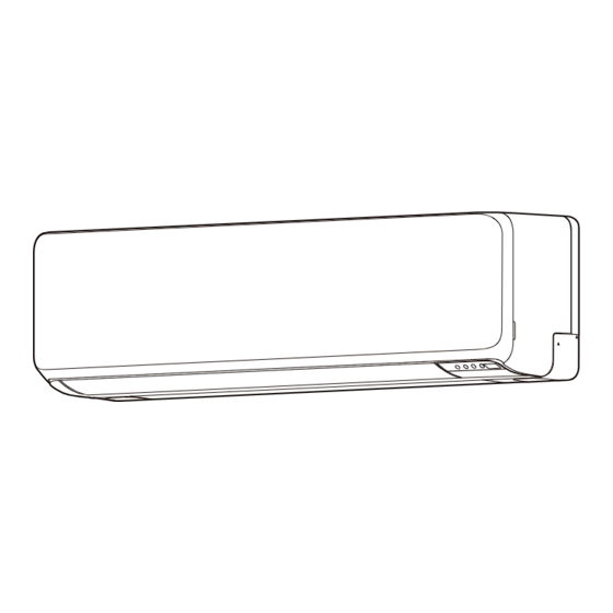
AIR CONDITIONER
Wall-mounted Type
For authorized service personnel only.
• Branch box which is specifi ed in this manual is the equipment to support the indoor unit
of multi-connection type.
• All products are manufactured to metric units and tolerances. United States customary
units are provided for reference only. In cases where exact dimensions and tolerances
are required, always refer to metric units.
Contents
1.
SAFETY PRECAUTIONS .................................................................. 1
1.1. IMPORTANT! Read before starting ............................................ 1
1.2. Special precautions .................................................................... 1
2.
PRODUCT SPECIFICATION ............................................................. 2
2.1. Precautions for using R410A refrigerant ..................................... 2
2.2. Installation tools .......................................................................... 2
2.3. For authorized service personnel only. ....................................... 2
2.4. Accessories ................................................................................ 2
2.5. Pipe requirement ........................................................................ 3
2.6. Electrical requirement ................................................................. 3
2.7. Optional parts ............................................................................. 3
3.
INSTALLATION WORK ..................................................................... 3
3.1. Selecting an installation location ................................................ 3
3.2. Removing and replacing parts .................................................... 3
3.3. Pipe installation .......................................................................... 4
3.4. Electrical wiring ........................................................................... 6
3.5. Remote controller installation ..................................................... 7
4.
OPTIONAL INSTALLATION WORK .................................................. 8
4.1. Optional kit installation ................................................................ 8
4.2. Group control .............................................................................. 9
5.
FUNCTION SETTING...................................................................... 10
5.1. Function details ........................................................................ 10
5.2. Temperature correction ..............................................................11
6.
TEST RUN ....................................................................................... 12
7.
FINISHING ...................................................................................... 12
8.
CUSTOMER GUIDANCE ................................................................ 12
9.
ERROR CODES .............................................................................. 13
1. SAFETY PRECAUTIONS
1.1. IMPORTANT! Read before starting
This air conditioning system meets strict safety and operating standards.
As the installer or service person, it is an important part of your job to install or service the
system so it operates safely and effi ciently.
For safe installation and trouble-free operation, you must:
• Carefully read this instruction booklet before beginning.
• Follow each installation or repair step exactly as shown.
• Observe all local, state, and national electrical codes.
• Pay close attention to all warning and caution notices given in this manual.
This symbol refers to a hazard or unsafe practice which can
WARNING
result in severe personal injury or death.
This symbol refers to a hazard or unsafe practice which can
result in personal injury and the potential for product or prop-
CAUTION
erty damage.
INSTALLATION MANUAL
• Hazard alerting symbols
Electrical
If Necessary, Get Help
These instructions are all you need for most installation sites and maintenance conditions.
If you require help for a special problem, contact our sales/service outlet or your certifi ed
dealer for additional instructions.
In Case of Improper Installation
The manufacturer shall in no way be responsible for improper installation or maintenance
service, including failure to follow the instructions in this document.
1.2. Special precautions
When Wiring
ELECTRICAL SHOCK CAN CAUSE SEVERE PERSONAL INJURY OR DEATH. ONLY A
QUALIFIED, EXPERIENCED ELECTRICIAN SHOULD ATTEMPT TO WIRE THIS SYS-
TEM.
• Do not supply power to the unit until all wiring and tubing are completed or reconnected
and checked.
• Highly dangerous electrical voltages are used in this system. Carefully refer to the wir-
ing diagram and these instructions when wiring. Improper connections and inadequate
grounding (earthing) can cause accidental injury or death.
• Ground (earth) the unit following local electrical codes.
• Connect all wiring tightly. Loose wiring may cause overheating at connection points and
a possible fi re hazard.
When Transporting
Be careful when picking up and moving the indoor and outdoor units. Get a partner to
help, and bend your knees when lifting to reduce strain on your back. Sharp edges or thin
aluminum fi ns on the air conditioner can cut your fi ngers.
When Installing...
...In a Ceiling or Wall
Make sure the ceiling/wall is strong enough to hold the unit's weight. It may be necessary
to construct a strong wood or metal frame to provide added support.
...In a Room
Properly insulate any tubing run inside a room to prevent "sweating" that can cause drip-
ping and water damage to walls and fl oors.
...In an Area with High Winds
Securely anchor the outdoor unit down with bolts and a metal frame.
Provide a suitable air baffl e.
...In a Snowy Area (for Heat Pump-type Systems)
Install the outdoor unit on a raised platform that is higher than drifting snow.
When Connecting Refrigerant Tubing
• Keep all tubing runs as short as possible.
• Use the fl are method for connecting tubing.
• Apply refrigerant lubricant to the matching surfaces of the fl are and union tubes before
connecting them, then tighten the nut with a torque wrench for a leak-free connection.
• Check carefully for leaks before opening the refrigerant valves.
When Servicing
• Turn the power OFF at the main circuit breaker panel before opening the unit to check
or repair electrical parts and wiring.
• Keep your fi ngers and clothing away from any moving parts.
• Clean up the site after you fi nish, remembering to check that no metal scraps or bits of
wiring have been left inside the unit being serviced.
• After installation, explain correct operation to the customer, using the operation manual.
• Never touch electrical components immediately after the power supply has been
turned off . Electric shock may occur. After turning off the power, always wait 10 min-
utes before touching electrical components.
• If refrigerant leaks while work is being carried out, ventilate the area. If the refrigerant
comes in contact with a fl ame, it produces a toxic gas.
• Keep any required ventilation openings clear of obstruction.
• If the power cable or the connection cable is damaged, it must be replaced by the
manufacturer, its service agent or similar qualifi ed persons in order to avoid a safety
hazard.
• Cancer and Reproductive Harm - www.P65Warnings.ca.gov.
PART No. 9387603217-01
Safety/alert
WARNING
En-1
Advertisement
Table of Contents

Related Manuals for Fujitsu ASUH15LPAS


Summary of Contents for Fujitsu ASUH15LPAS
-
Page 1: Table Of Contents
INSTALLATION MANUAL AIR CONDITIONER Wall-mounted Type PART No. 9387603217-01 • Hazard alerting symbols Safety/alert Electrical If Necessary, Get Help These instructions are all you need for most installation sites and maintenance conditions. If you require help for a special problem, contact our sales/service outlet or your certifi ed dealer for additional instructions. -
Page 2: Product Specification
CAUTION CAUTION • Do not attempt to install the air conditioner or a part of the air conditioner by yourself. This manual describes how to install the indoor unit only. To install the outdoor unit or • This unit must be installed by qualifi ed personnel with a capacity certifi cate for han- branch box, (if any), refer to the installation manual included in each product. -
Page 3: Pipe Requirement
2.5. Pipe requirement WARNING Install the air conditioner in a location which can withstand a load of at least 3 times the CAUTION weight of the main unit and which will not amplify sound or vibration. If the installation location is not strong enough, the indoor unit may fall and cause injuries. Refer to the installation manual for the outdoor unit for description of allowable pipe length Withstandable weight (Unit weight x 3*) and height diff... -
Page 4: Pipe Installation
■ Front panel / control cover / under cover (L/R/C) installation Mounting shaft Install the previous fi gure in reverse order. * Be sure to attach the screws (4 places), screw cover(2 places) for front panel and screws (2 places), cap screw (2 places) for under cover C. Mounting CAUTION shaft... - Page 5 Removing the drain hose Installing the drain hose WARNING Remove the screw at the left of Vertically insert the drain hose toward the drain hose and pull out drain hose. inside, so that the drain fi xture (white) can ac- Always use the wall pipe.
-
Page 6: Electrical Wiring
Dimension A [in. (mm)] 3.4. Electrical wiring Pipe outside diameter Dimension B [in. (mm)] Flare tool for R410A, [in. (mm)] clutch type WARNING 1/4 (6.35) 3/8 (9.1) • Before connecting the wires, make sure the power supply is OFF. 3/8 (9.52) 1/2 (13.2) •... -
Page 7: Remote Controller Installation
3.4.2. How to the install the connection cable (5) Do not tighten the terminal screws too much, otherwise, the screws may break. (1) Remove the screws, then remove the conduit holder. Screw with special washer Screw with special washer (2) Fasten the indoor unit wire harness to the conduit holder using the lock nut. IMPORTANT: Refer to “3.4.1. -
Page 8: Optional Installation Work
3.5.2. Remote controller custom setting 4.1. Optional kit installation ■ Custom code setting NOTE: By setting custom code of indoor unit and remote controller, you can specify the air condi- When some wired remote controller is connected, the wireless remote controller cannot tioner which the remote controller controls. -
Page 9: Group Control
4.1.4. Installing the communication kit Output select ● When interlocking with external device Remove the Intake grille, front panel, and control cover. Refer to “3.2. Removing and replacing parts”. Insert the PCB to the clasps (2 places). Push the PCB down until the clasp on the Connected bottom is set. -
Page 10: Function Setting
STEP 2 Example of wiring method Setting the function number and setting value Indoor unit 1 Indoor unit 2 Indoor unit 3 Indoor unit 4 (1) Press [TEMP./SELECT ( )] to select the function number. (Press [MODE] to switch between the left and right digits.) Function number... -
Page 11: Temperature Correction
■ Heat pump backup setting ■ External input control Enables or disables the heat pump backup instruction from the outdoor unit. “Operation/Stop” mode or “Forced stop” mode can be selected. This function will be usable provided that the corresponding outdoor unit is connected. (♦... -
Page 12: Test Run
■ Operation method Setting Function number Setting description value Before starting the test run, wait for 1 minute after connecting the power supply. Standard setting ♦ By the wireless remote controller No correction 0 °F (0.0 °C) To start the test run, press [START/STOP( )], press and hold [ ] on the remote control for 5 seconds or more by using the tip of a ballpoint pen or other small object. -
Page 13: Error Codes
Error display 9. ERROR CODES Error code* Description LED1 LED2 LED3 If you use a wireless remote controller, the lamp on the photo detector unit will output error (green) (orange) (green) codes by way of blinking patterns. If you use a wired remote controller, error codes will ap- Electric air cleaner reverse VDD pear on the remote control display. - Page 14 ■ Error code on the wired remote controller (option) Check the error If an error occurs, an error icon appears on the “Monitor mode screen”. Touch the [Status] on the “Monitor mode screen”. The “Status” screen is dis- played. Touch the [Error Information] on the “Status” screen. The “Error Information” screen is displayed.
Need help?
Do you have a question about the ASUH15LPAS and is the answer not in the manual?
Questions and answers