MSI MAG B760 TOMAHAWK WIFI - Motherboard Manual
- User manual (436 pages) ,
- User manual (65 pages)
Advertisement
- 1 Quick Start
- 2 Case stand-off notification
- 3 Avoid collision notification
- 4 Installing a Processor
- 5 Installing DDR5 memory
- 6 Connecting the Front Panel Header
- 7 Installing the Motherboard
- 8 Connecting the Power Connectors
- 9 Installing SATA Drives
- 10 Installing a Graphics Card
- 11 Connecting Peripheral Devices
- 12 Power On
- 13 Specifications
- 14 Special Features
- 15 Package Contents
- 16 Back Panel Connectors
- 17 Overview of Components
- 18 Onboard LEDs
- 19 Installing OS, Drivers & MSI Center
- 20 MSI Center
- 21 UEFI BIOS
- 22 Safety Information
- 23 Documents / Resources
Quick Start
Thank you for purchasing a new motherboard from MSI®. This Quick Start section provides demonstration diagrams about how to install your computer. Some of the installations also provide video demonstrations. Please link to the URL to watch it with the web browser on your phone or tablet. You may have even link to the URL by scanning the QR code.
Preparing Tools and Components

Case stand-off notification
To prevent damage to the motherboard, any unnecessary mounting stand-off between the motherboard circuits and the computer case is prohibited. The Case standoff keep out zone signs will be marked on the backside of motherboard (as shown below) to serve as a warning to user.
Avoid collision notification
Protective paint is printed around each screw hole to prevent parts from being scratched.

Installing a Processor


Installing DDR5 memory


Connecting the Front Panel Header


Installing the Motherboard


Connecting the Power Connectors


Installing SATA Drives


Installing a Graphics Card


Connecting Peripheral Devices

Power On

Specifications
| CPU |
|
| Chipset | Intel® B760 Chipset |
| Memory |
|
| Expansion Slots |
|
| Onboard Graphics |
|
| SATA Ports | 4x SATA 6Gb/s ports* (From B760 chipset) * SATA7 will be unavailable when installing M2.SATA SSD in the M2_3 slot. |
| M.2 SSD Slots |
|
| RAID |
|
| Audio | Realtek® ALC897 Codec
|
| LAN | 1x Realtek® RTL8125BG-CG 2.5Gbps LAN controller |
| Wi-Fi & Bluetooth® | Intel® Wi-Fi 6E
|
| Power Connectors |
|
| Internal USB Connectors |
|
| Fan Connectors |
|
| System Connectors |
|
| Jumpers |
|
| LED Features |
|
| Back Panel Connectors |
|
| I/O Controller | NUVOTON NCT6687 Controller Chip |
| Hardware Monitor |
|
| Form Factor |
|
| BIOS Features |
|
| Software |
|
Special Features
MSI Center
- Gaming Mode
- Smart Priority
- Game Highlights
- Mystic Light
- Ambient Link
- Frozr AI Cooling
- User Scenario
- True Color
- Live Update
- Hardware Monitoring
- Super Charger
- Devices Speed Up
- Smart Image Finder
- MSI Companion
- System Diagnosis
Thermal Features
- Extended Heatsink Design
- M.2 Shield Frozr
- K7 MOSFET thermal pad / Extra choke pad
- Fan headers
Performance
- Core Boost
- VRM Power Design
- Dual CPU Power
- Memory Boost
- Lightning Gen 4 PCI-E / M.2 Slot
- Front USB Type-C
- 2oz Copper thickened PCB
DIY Friendly
- PCI-E Steel Armor
- Pre-installed I/O Shield
- EZ M.2 Clips
- EZ DEBUG LED
- EZ LED Control
Audio
- Audio Boost
RGB Support
- Mystic Light Extension (RGB)
- Mystic Light Extension (A-RAINBOW V2)
- Ambient Devices Support
BIOS
- Click BIOS 5
Package Contents
Please check the contents of your motherboard package. It should contain:
Board
- 1x Motherboard
Documentation
- 1x Quick installation guide
- 1x European Union regulatory notice
Cables
- 1x SATA 6Gb/s cable
Accessories
- 1x Wi-Fi antenna set
- 1x EZ M.2 Clip package (1 set/pack)
- 1x Cable sticker

If any of the above items are damaged or missing, please contact your retailer.
Back Panel Connectors

| Item | Description |
| 1 | USB 2.0 Type-A ports (From Hub GL850G) |
| 2 | DisplayPort |
| 3 | USB 3.2 Gen 2 10Gbps Type-A ports (From GL3590 Hub) |
| 4 | 2.5 Gbps LAN (RJ45) port |
| 5 | Wi-Fi antenna connectors |
| 6 | Audio jacks |
| 7 | HDMI™ port  |
| 8 | USB 3.2 Gen 2x2 20Gbps Type-C port (From B760 chipset) |
| 9 | Optical S/PDIF Out connector |
LAN Port LED Status Table

Audio Jacks Connection
Audio jacks to headphone and microphone diagram

Audio jacks to stereo speakers diagram

Audio jacks to 4-channel speakers diagram

Audio jacks to 5.1-channel speakers diagram

Audio jacks to 7.1-channel speakers diagram

Installing antennas
- Screw the antennas tight to the antenna connectors as shown below.

- Orient the antennas.


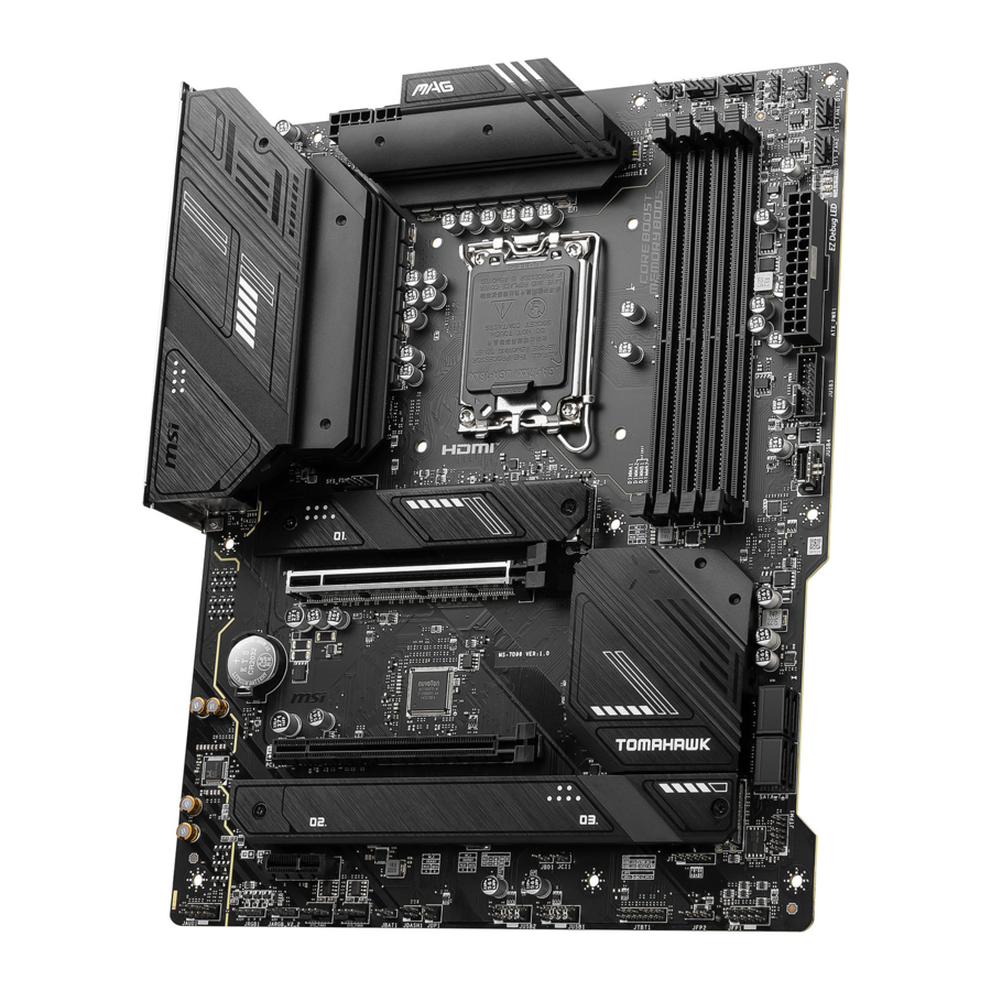
Overview of Components

CPU Socket

Introduction to the LGA1700 CPU
The surface of the LGA1700 CPU has four notches and a golden triangle to assist in correctly lining up the CPU for motherboard placement. The golden triangle is the Pin 1 indicator.
- Always unplug the power cord from the power outlet before installing or removing the CPU.
- Please retain the CPU protective cap after installing the processor. MSI will deal with Return Merchandise Authorization (RMA) requests if only the motherboard comes with the protective cap on the CPU socket.
- When installing a CPU, always remember to install a CPU heatsink. A CPU heatsink is necessary to prevent overheating and maintain system stability.
- Confirm that the CPU heatsink has formed a tight seal with the CPU before booting your system.
- Overheating can seriously damage the CPU and motherboard. Always make sure the cooling fans work properly to protect the CPU from overheating. Be sure to apply an even layer of thermal paste (or thermal tape) between the CPU and the heatsink to enhance heat dissipation.
- Whenever the CPU is not installed, always protect the CPU socket pins by covering the socket with the plastic cap.
- If you purchased a separate CPU and heatsink/ cooler, Please refer to the documentation in the heatsink/ cooler package for more details about installation.
- This motherboard is designed to support overclocking. Before attempting to overclock, please make sure that all other system components can tolerate overclocking. Any attempt to operate beyond product specifications is not recommended. MSI® does not guarantee the damages or risks caused by inadequate operation beyond product specifications.
DIMM Slots

Memory module installation

- To ensure system stability for Dual channel mode, memory modules must be of the same type, number and density.
- Some memory modules may operate at a lower frequency than the marked value when overclocking due to the memory frequency operates dependent on its Serial Presence Detect (SPD). Go to BIOS and find the DRAM Frequency to set the memory frequency if you want to operate the memory at the marked or at a higher frequency.
- It is recommended that users use a more efficient memory cooling system for full DIMMs installation or overclocking.
- The stability and compatibility of installed memory module depend on installed CPU and devices when overclocking.
- Please refer to www.msi.com for more information on compatible memory.
PCI_E1~3: PCIe Expansion Slots

PCI_E1: PCIe 5.0 x16 (From CPU)
PCI_E2: PCIe 3.0 x4 (From B760 chipset)
PCI_E3: PCIe 4.0 x1 (From B760 chipset)
- If you install a large and heavy graphics card, you need to use a tool such as MSI Graphics Card Bolster to support its weight to prevent deformation of the slot.
- When adding or removing expansion cards, always turn off the power supply and unplug the power supply power cable from the power outlet. Read the expansion card's documentation to check for any necessary additional hardware or software changes.
SATA_5~8: SATA 6Gb/s Connectors
These connectors are SATA 6Gb/s interface ports. Each connector can connect to one SATA device.

- Please do not fold the SATA cable at a 90-degree angle. Data loss may result during transmission otherwise.
- SATA cables have identical plugs on either sides of the cable. However, it is recommended that the flat connector be connected to the motherboard for space saving purposes.
- SATA_7 will be unavailable when installing M.2 SATA SSD in M2_3 slot.
M2_1~3: M.2 Slots (Key M)
- Intel® RST only supports PCIe M.2 SSD with UEFI ROM.
- If your M.2 SSD equips its own heatsink, please remove the M.2 plates or rubber cubes in the M.2 slots before installing M.2 SSD. Do not re-install the heatsinks supplied with your motherboard.
Installing M.2 module into M2_1 slot
- Loosen the screws of M.2 Shield Frozr heatsink.
- Lift up the M.2 Shield Frozr heatsink and remove it.

- Remove or exchange the screws according to your SSD length. Skip this step, if you install 2280 SSD.

- Insert your M.2 SSD into the M.2 slot at a 30-degree angle.
- Rotate the EZ M.2 Clip to fix the M.2 SSD.

- Remove the protective film from the thermal pad under the M.2 Shield Frozr heatsink.
- Put the M.2 Shield Frozr heatsink back in place and secure it.


Installing M.2 module into M2_2 & M2_3 slots
- Loosen the screws of M.2 Shield Frozr heatsink.
- Lift up the M.2 Shield Frozr heatsink and remove it.

- If you want to install 2242 or 2260 M.2 SSD, please install the supplied EZ M.2 Clip kit in the 2240 or 2260 screw hole. Skip this step, if you install 2280 SSD.
- M2_2 slot

- M2_3 slot

- M2_2 slot
- Insert your M.2 SSD into the M.2 slot at a 30-degree angle.
- Rotate the EZ M.2 Clip to fix the M.2 SSD.
- M2_2 slot

- M2_3 slot

- M2_2 slot
- Remove the protective film from the thermal pad under the M.2 Shield Frozr heatsink.
- Put the M.2 Shield Frozr heatsink back in place and secure it.


JAUD1: Front Audio Connector
This connector allows you to connect audio jacks on the front panel.


| Pin | Signal Name | Pin | Signal Name |
| 1 | MIC L | 2 | Ground |
| 3 | MIC R | 4 | NC |
| 5 | Head Phone R | 6 | MIC Detection |
| 7 | SENSE_SEND | 8 | No Pin |
| 9 | Head Phone L | 10 | Head Phone Detection |
JFP1, JFP2: Front Panel Connectors
The JFP1 connector controls the power on, power reset, and the LEDs on your PC case/chassis. Power Switch/ Reset Switch headers allow you to connect power button/ reset button. Power LED header connects to LED light on the PC case, and HDD LED header indicates the activity of the hard disk. The JFP2 connector is for Buzzer and Speaker. To connect the cables from PC case to the right pins, please refer to the following images below.


Please note that Power LED and HDD LED have positive and negative connection, you need to link up the cable to the corresponding positive and negative port on the motherboard. Otherwise, LEDs won't work properly.
JCI1: Chassis Intrusion Connector
This connector allows you to connect the chassis intrusion switch cable.


Normal (default)

Trigger the chassis intrusion event
Using chassis intrusion detector
- Connect the JCI1 connector to the chassis intrusion switch/ sensor on the chassis.
- Close the chassis cover.
- Go to BIOS > SETTINGS > Security > Chassis Intrusion Configuration.
- Set Chassis Intrusion to Enabled.
- Press F10 to save and exit and then press the Enter key to select Yes.
- Once the chassis cover is opened again, a warning message will be displayed on screen when the computer is turned on.
Resetting the chassis intrusion warning
- Go to BIOS > SETTINGS > Security > Chassis Intrusion Configuration.
- Set Chassis Intrusion to Reset.
- Press F10 to save and exit and then press the Enter key to select Yes.
CPU_PWR1~2, ATX_PWR1: Power Connectors
These connectors allow you to connect an ATX power supply.
CPU_PWR1~2


| Pin | Signal Name | Pin | Signal Name |
| 1 | Ground | 2 | Ground |
| 3 | Ground | 4 | Ground |
| 5 | +12V | 6 | +12V |
| 7 | +12V | 8 | +12V |
ATX_PWR1

| Pin | Signal Name | Pin | Signal Name |
| 1 | +3.3V | 2 | +3.3V |
| 3 | Ground | 4 | +5V |
| 5 | Ground | 6 | +5V |
| 7 | Ground | 8 | PWR OK |
| 9 | 5VSB | 10 | +12V |
| 11 | +12V | 12 | +3.3V |
| 13 | +3.3V | 14 | -12V |
| 15 | Ground | 16 | PS-ON# |
| 17 | Ground | 18 | Ground |
| 19 | Ground | 20 | Res |
| 21 | +5V | 22 | +5V |
| 23 | +5V | 24 | Ground |
Make sure that all the power cables are securely connected to a proper ATX power supply to ensure stable operation of the motherboard.
JTBT1: Thunderbolt Add-on Card Connector
This connector allows you to connect the add-on Thunderbolt I/O card.

| Pin | Signal Name | Pin | Signal Name |
| 1 | TBT_FORCE_PWR | 2 | TBT_S0IX_ENTRY_REQ |
| 3 | TBT_CIO_PLUG_EVENT# | 4 | TBT_S0IX_ENTRY_ACK |
| 5 | SLP_S3#_TBT | 6 | TBT_PSON_ OVERRIDE_N |
| 7 | SLP_S5#_TBT | 8 | No Pin |
| 9 | Ground | 10 | SMBCLK_VSB |
| 11 | DG_PEWAKE# | 12 | SMBDATA_VSB |
| 13 | TBT_RTD3_PWR_EN | 14 | Ground |
| 15 | TBT_CARD_DET_R# | 16 | PD_IRQ# |
JTPM1: TPM Module Connector
This connector is for TPM (Trusted Platform Module). Please refer to the TPM security platform manual for more details and usages.


| Pin | Signal Name | Pin | Signal Name |
| 1 | SPI Power | 2 | SPI Chip Select |
| 3 | Master In Slave Out (SPI Data) | 4 | Master Out Slave In (SPI Data) |
| 5 | Reserved | 6 | SPI Clock |
| 7 | Ground | 8 | SPI Reset |
| 9 | Reserved | 10 | No Pin |
| 11 | Reserved | 12 | Interrupt Request |
JUSB4: USB 3.2 Gen 2 Type-C Front Panel Connector
This connector allows you to connect USB 3.2 Gen 2 10Gbps Type-C connector on the front panel. The connector has a foolproof design. When you connect the cable, be sure to connect it with the corresponding orientation.

JUSB3: USB 3.2 Gen 1 Connector
This connector allows you to connect USB 3.2 Gen 1 5Gbps ports on the front panel.

| Pin | Signal Name | Pin | Signal Name |
| 1 | Power | 2 | USB3_RX_DN |
| 3 | USB3_RX_DP | 4 | Ground |
| 5 | USB3_TX_C_DN | 6 | USB3_TX_C_DP |
| 7 | Ground | 8 | USB2.0- |
| 9 | USB2.0+ | 10 | Ground |
| 11 | USB2.0+ | 12 | USB2.0- |
| 13 | Ground | 14 | USB3_TX_C_DP |
| 15 | USB3_TX_C_DN | 16 | Ground |
| 17 | USB3_RX_DP | 18 | USB3_RX_DN |
| 19 | Power | 20 | No Pin |
Note that the Power and Ground pins must be connected correctly to avoid possible damage.
JUSB1~2: USB 2.0 Connectors
These connectors allow you to connect USB 2.0 ports on the front panel.


| Pin | Signal Name | Pin | Signal Name |
| 1 | VCC | 2 | VCC |
| 3 | USB0- | 4 | USB1- |
| 5 | USB0+ | 6 | USB1+ |
| 7 | Ground | 8 | Ground |
| 9 | No Pin | 10 | NC |
- Note that the VCC and Ground pins must be connected correctly to avoid possible damage.
- In order to recharge your iPad, iPhone and iPod through USB ports, please install MSI Center utility.
JDASH1: Tuning Controller Connector
This connector is used to connect an optional Tuning Controller module.


| Pin | Signal Name | Pin | Signal Name |
| 1 | No Pin | 2 | NC |
| 3 | MCU_SMB_SCL_M | 4 | MCU_SMB_SDA_M |
| 5 | VCC5 | 6 | Ground |
CPU_FAN1, PUMP_FAN1, SYS_FAN1~5: Fan Connectors
Fan connectors can be classified as PWM (Pulse Width Modulation) Mode or DC Mode. PWM Mode fan connectors provide constant 12V output and adjust fan speed with speed control signal. DC Mode fan connectors control fan speed by changing voltage.
You can control fans in BIOS> HARDWARE MONITOR panel. It allows you to set DC or PWM to your fan type. Check the Smart Fan Mode, the fan speed will change according to the CPU or system temperature. Uncheck the Smart Fan Mode, the fan will spin at maximum speed.
Make sure fans are working properly after switching the PWM/ DC mode.


PWM Mode pin definition
| Pin | Signal Name | Pin | Signal Name |
| 1 | Ground | 2 | +12V |
| 3 | Sense | 4 | Speed Control Signal |
DC Mode pin definition
| Pin | Signal Name | Pin | Signal Name |
| 1 | Ground | 2 | Voltage Control |
| 3 | Sense | 4 | NC |
Fan connector specifications
| Connector | Default fan mode | Max. current | Max. power |
| CPU_FAN1 | PWM mode | 2A | 24W |
| PUMP_FAN1 | PWM mode | 3A | 36W |
| SYS_FAN1~5 | DC mode | 2A | 24W |
JBAT1: Clear CMOS (Reset BIOS) Jumper
There is CMOS memory onboard that is external powered from a battery located on the motherboard to save system configuration data. If you want to clear the system configuration, set the jumpers to clear the CMOS memory.


Keep Data (default)

Clear CMOS/ Reset BIOS
Resetting BIOS to default values
- Power off the computer and unplug the power cord.
- Use a jumper cap to short JBAT1 for about 5-10 seconds.
- Remove the jumper cap from JBAT1.
- Plug the power cord and Power on the computer.
BAT1: CMOS Battery
If the CMOS battery is out of charge, the time in the BIOS will be reset and the data of system configuration will be lost. In this case, you need to replace the CMOS battery.
Replacing CMOS battery

- Push the retainer clip to free the battery.
- Remove the battery from the socket.
- Install the new CR2032 coin-cell battery with the + sign facing up. Ensure that the retainer holds the battery securely.


JRGB1~2: RGB LED Connectors
The JRGB connectors allow you to connect the 5050 RGB LED strips 12V.


| Pin | Signal Name | Pin | Signal Name |
| 1 | +12V | 2 | G |
| 3 | R | 4 | B |
RGB LED Strip Connection

RGB LED Fan Connection

- The JRGB connector supports up to 2 meters continuous 5050 RGB LED strips (12V/G/R/B) with the maximum power rating of 3A (12V).
- Always turn off the power supply and unplug the power cord from the power outlet before installing or removing the RGB LED strip.
- Please use MSI's software to control the extended LED strip.
JARGB_V2_1~2: A-RAINBOW V2 (ARGB Gen2) LED Connectors
The JARGB_V2 connectors allow you to connect the ARGB Gen2 and the ARGB-based LED strips. The JARGB_V2 connector supports up to 240 individually addressable RGB LEDs with maximum power rating of 3A (5V).


| Pin | Signal Name | Pin | Signal Name |
| 1 | +5V | 2 | Data |
| 3 | No Pin | 4 | Ground |
Addressable RGB LED Strip Connection

Addressable RGB LED Fan Connection


Do not connect the wrong type of LED strips. The JRGB connector and the JARGB_V2 connector provide different voltages, and connecting the ARGB 5V LED strip to the JRGB connector will result in damage to the LED strip.
- If you connect ARGB Gen1 and ARGB Gen2 LED strips into the same connector, it may cause issues. Please do not mix ARGB Gen1 and ARGB Gen2 LED strips together.
- It is recommended that you install LED strips with the same specification to achieve the best effects.
- Always turn off the power supply and unplug the power cord from the power outlet before installing or removing the addressable RGB LED strip.
- Please use MSI's software to control the extended LED strip.
Onboard LEDs
EZ Debug LED
These LEDs indicate the debug status of the motherboard.

 CPU - indicates CPU is not detected or fail.
 DRAM - indicates DRAM is not detected or fail.
 VGA - indicates GPU is not detected or fail.
 BOOT - indicates the booting device is not detected or fail.
Installing OS, Drivers & MSI Center
Please download and update the latest utilities and drivers at www.msi.com
Installing Windows 10/ Windows 11
- Power on the computer.
- Insert the Windows 10/ Windows 11 installation disc/USB into your computer.
- Press the Restart button on the computer case.
- Press F11 key during the computer POST (Power-On Self Test) to get into Boot Menu.
- Select the Windows 10/ Windows 11 installation disc/USB from the Boot Menu.
- Press any key if screen shows Press any key to boot from CD or DVD... message. If not, please skip this step.
- Follow the instructions on the screen to install Windows 10/ Windows 11.
Installing Drivers with MSI Driver Utility Installer
- Some new network chips have not been natively supported by Windows 10/ Windows 11. It is recommended that the LAN driver be installed before installing drivers with MSI Driver Utility Installer. Please refer to www.msi.com to install the LAN driver for your motherboard.
- The MSI Driver Utility Installer will only pop up once. If you cancel or close it during the process, please refer to the Live Update chapter of the MSI Center manual to install the drivers. You can also go to www.msi.com to search your motherboard and download the drivers.
- MSI Driver Utility Installer needs to be installed over the internet.
- Start up your computer in Windows 10/ Windows 11.
- Select Start > Settings > Windows Update, and then select Check for updates.
- MSI Driver Utility Installer will pop up automatically.

- Select the I have read and agree to the MSI Terms of Use check box, and then click Next.

- Check the Select All checkbox in the lower-left corner and click Install to install MSI Center and drivers. The installation progress will be shown at the bottom.

- Once the progress has completed, click Finish.


MSI Center
MSI Center is an application that helps you easily optimize game settings and smoothly use content creation softwares. It also allows you to control and synchronize LED light effects on PCs and other MSI products. With MSI Center, you can customize ideal modes, monitor system performance, and adjust fan speed.
MSI Center User Guide

If you would like to know more information about MSI Center, please refer to http://download.msi.com/manual/mb/MSICENTER.pdf or scan the QR code to access.
Functions may vary depending on the product you have.
UEFI BIOS
MSI UEFI BIOS is compatible with UEFI (Unified Extensible Firmware Interface) architecture. UEFI has many new functions and advantages that traditional BIOS cannot achieve, and it will completely replace BIOS in the future. The MSI UEFI BIOS uses UEFI as the default boot mode to take full advantage of the new chipset's capabilities.
The term BIOS in this user guide refers to UEFI BIOS unless otherwise noted.
UEFI advantages
- Fast booting - UEFI can directly boot the operating system and save the BIOS selftest process. And also eliminates the time to switch to CSM mode during POST.
- Supports for hard drive partitions larger than 2 TB.
- Supports more than 4 primary partitions with a GUID Partition Table (GPT).
- Supports unlimited number of partitions.
- Supports full capabilities of new devices - new devices may not provide backward compatibility.
- Supports secure startup - UEFI can check the validity of the operating system to ensure that no malware tampers with the startup process.
Incompatible UEFI cases
- 32-bit Windows operating system - this motherboard supports only Windows 10/ Windows 11 64-bit operating system.
- Older graphics card - the system will detect your graphics card. If you use older graphics cards, it may display a warning message There is no GOP (Graphics Output protocol) support detected in this graphics card.
We recommend that you replace it with a graphics card supporting GOP/UEFI or use CPU with integrated graphics for having normal function.
How to check the BIOS mode?
- Power on your computer.
- Press Delete key, when the Press DEL key to enter Setup Menu, F11 to enter Boot Menu message appears on the screen during the boot process.
- After entering the BIOS, you can check the BIOS Mode at the top of the screen.
![]()

BIOS Setup
The default settings offer the optimal performance for system stability in normal conditions. You should always keep the default settings to avoid possible system damage or failure booting unless you are familiar with BIOS.
- BIOS items are continuously update for better system performance. Therefore, the description may be slightly different from the latest BIOS and should be for reference only. You could also refer to the HELP information panel for BIOS item description.
- The BIOS screens, options and settings will vary depending on your system.
Entering BIOS Setup
Press Delete key, when the Press DEL key to enter Setup Menu, F11 to enter Boot Menu message appears on the screen during the boot process.
Function key
| F1: | General Help list |
| F2: | Add/ Remove a favorite item |
| F3: | Enter Favorites menu |
| F4: | Enter CPU Specifications menu |
| F5: | Enter Memory-Z menu |
| F6: | Load optimized defaults |
| F7: | Switch between Advanced mode and EZ mode |
| F8: | Load Overclocking Profile |
| F9: | Save Overclocking Profile |
| F10: | Save Change and Reset* |
| F12: | Take a screenshot and save it to USB flash drive (FAT/ FAT32 format only). |
| Ctrl+F: | Enter Search page |
* When you press F10, a confirmation window appears and it provides the modification information. Select between Yes or No to confirm your choice.
BIOS User Guide

If you'd like to know more instructions on setting up the BIOS, please refer to https://download.msi.com/archive/mnu_exe/mb/Intel700BIOS.pdf or scan the QR code to access.
Functions may vary depending on the product you have.
Resetting BIOS
You might need to restore the default BIOS setting to solve certain problems. There are several ways to reset BIOS:
- Go to BIOS and press F6 to load optimized defaults.
- Short the Clear CMOS jumper on the motherboard.
Be sure the computer is off before clearing CMOS data. Please refer to the Clear CMOS jumper section for resetting BIOS.
Updating BIOS
Updating BIOS with M-FLASH
Before updating:
Please download the latest BIOS file that matches your motherboard model from MSI website. And then save the BIOS file into the USB flash drive.
Updating BIOS:
- Switch to the target BIOS ROM by Multi-BIOS switch. Please skip this step if your motherboard doesn't has this switch.
- Insert the USB flash drive that contains the update file into the USB port.
- Please refer the following methods to enter flash mode.
- Reboot and press Ctrl + F5 key during POST and click on Yes to reboot the system.
Press <Ctrl+F5> to activate M-Flash for BIOS update.

- Reboot and press Del key during POST to enter BIOS. Click the M-FLASH button and click on Yes to reboot the system.

- Reboot and press Ctrl + F5 key during POST and click on Yes to reboot the system.
- Select a BIOS file to perform the BIOS update process.
- When prompted click on Yes to start recovering BIOS.
- After the flashing process is 100% completed, the system will reboot automatically.


Updating the BIOS with MSI Center
Before updating:
- Make sure the LAN driver is already installed and the internet connection is set properly.
- Please close all other application software before updating the BIOS.
To update BIOS:
- Install and launch MSI Center and go to Support page.
- Select Live Update and click on Advance button.
- Select the BIOS file and click on Install button.
- The installation reminder will appear, then click the Install button on it.
- The system will automatically restart to update BIOS.
- After the flashing process is 100% completed, the system will restart automatically.
Safety Information
- The components included in this package are prone to damage from electrostatic discharge (ESD). Please adhere to the following instructions to ensure successful computer assembly.
- Ensure that all components are securely connected. Loose connections may cause the computer to not recognize a component or fail to start.
- Hold the motherboard by the edges to avoid touching sensitive components.
- It is recommended to wear an electrostatic discharge (ESD) wrist strap when handling the motherboard to prevent electrostatic damage. If an ESD wrist strap is not available, discharge yourself of static electricity by touching another metal object before handling the motherboard.
- Store the motherboard in an electrostatic shielding container or on an anti-static pad whenever the motherboard is not installed.
- Before turning on the computer, ensure that there are no loose screws or metal components on the motherboard or anywhere within the computer case.
- Do not boot the computer before installation is completed. This could cause permanent damage to the components as well as injury to the user.
- If you need help during any installation step, please consult a certified computer technician.
- Always turn off the power supply and unplug the power cord from the power outlet before installing or removing any computer component.
- Keep this user guide for future reference. ∙ Keep this motherboard away from humidity.
- Make sure that your electrical outlet provides the same voltage as is indicated on the PSU, before connecting the PSU to the electrical outlet.
- Place the power cord such a way that people can not step on it. Do not place anything over the power cord.
- All cautions and warnings on the motherboard should be noted.
- If any of the following situations arises, get the motherboard checked by service personnel:
- Liquid has penetrated into the computer.
- The motherboard has been exposed to moisture.
- The motherboard does not work well or you can not get it work according to user guide.
- The motherboard has been dropped and damaged.
- The motherboard has obvious sign of breakage.
- Do not leave this motherboard in an environment above 60°C (140°F), it may damage the motherboard.

Documents / Resources
References
![youtu.be]() MSI® HOW-TO install front panel connectors (JFP1) - YouTube
MSI® HOW-TO install front panel connectors (JFP1) - YouTube![youtu.be]() MSI® HOW-TO Install motherboard with torque screwdriver - YouTube
MSI® HOW-TO Install motherboard with torque screwdriver - YouTube![youtu.be]() MSI® HOW-TO Install graphics card on PCIe x16 slot with butterfly lock - YouTube
MSI® HOW-TO Install graphics card on PCIe x16 slot with butterfly lock - YouTube![youtu.be]() MSI® HOW TO Install uninstall Intel LGA 1700 CPU - YouTube
MSI® HOW TO Install uninstall Intel LGA 1700 CPU - YouTube![youtu.be]() MSI® HOW-TO install or uninstall DIMM memory modules - YouTube
MSI® HOW-TO install or uninstall DIMM memory modules - YouTube![youtu.be]() MSI® HOW-TO install power supply connectors - YouTube
MSI® HOW-TO install power supply connectors - YouTube![youtu.be]() MSI® HOW-TO install SATA HDD - YouTube
MSI® HOW-TO install SATA HDD - YouTube![www.msi.com]() MSI - Redirect
MSI - Redirect![download.msi.com]() http://download.msi.com/manual/mb/MSICENTER.pdf
http://download.msi.com/manual/mb/MSICENTER.pdf![download.msi.com]() https://download.msi.com/archive/mnu_exe/mb/Intel700BIOS.pdf
https://download.msi.com/archive/mnu_exe/mb/Intel700BIOS.pdf
Download manual
Here you can download full pdf version of manual, it may contain additional safety instructions, warranty information, FCC rules, etc.
Advertisement


Need help?
Do you have a question about the MAG B760 TOMAHAWK WIFI and is the answer not in the manual?
Questions and answers