
Related Manuals for Toro Intelli-Sense TIS-612


Summary of Contents for Toro Intelli-Sense TIS-612
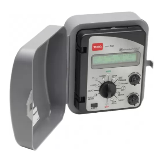
- Page 1 Intelli-Sense TIS-612 • User’s Guide • Setup • Installation • Programming • Operation...
-
Page 2: Table Of Contents
Table of Contents Introduction ..................1 Chapter 1 - Getting Started .............4 Control Module Components Internal Controller Components............6 Chapter 2 - Controller Setup About Controller Input ................ 7 Setting the Clock ................... 8 Setting the Time Zone................9 Selecting Auto Daylight Savings Option ........... - Page 3 Chapter 4 - Setting Up Station Programs (continued) Setting Up a User-defined Station Program ........29 Selecting the Station to Program ............29 Selecting the Program Mode .............30 Selecting the Water Window Option ..........30 Setting the Cycle Time ................30 Selecting the Number of Watering Cycles........31 Setting the Soak Time .................32 Setting the Usable Rainfall..............32 Selecting a Watering Day Schedule...
- Page 4 Chapter 5 - Control Functions (continued) Using the Alerts Function ..............55 Water Window Alert ................. 55 Day Pattern Alert ................56 Communication Alert................ 57 Valve Alert ..................57 Using the ET Function ................58 Viewing Current Daily and Weekly Average ET Values....58 Adjusting Custom Plant Kc Factor ...........59 Using the Manual Watering Function..........60...
-
Page 5: Introduction
In many cases, landscapes become conditioned to improper irrigation. Plants are prone to develop shallow root systems, making them vulnerable to drought, cold, heat stress and desease. The Toro Intelli-Sense controller is among the world’s most proven and reliable weather-based irrigation control solution available. - Page 6 Toro Intelli-Sense Intelli-Sense controllers Intelli-Sense...
-
Page 7: Chapter 1 Getting Started
Chapter 1 Getting Started The following checklist provides the basic recommended steps to guide you through the setup, programming and operation of your Intelli-Sense controller: Thoroughly inspect the entire irrigation system to ensure that all sprinklers and valves are working properly and that the water supply is sufficient to operate each sprinkler zone at optimum efficiency. -
Page 8: Control Module Components
Control Module Components Upper Line Lower Line - Information Display Large, easy-to-read digital display provides text information for controller setup, programming and operating functions. - Upper Line Dial Turn this dial left or right to select the menu items that appear on the upper line of the display. - Page 9 Function Dial Positions The normal dial position for automatic operation. Current time/date and controller activity is displayed. SETUP To select and define specific controller setup parameters. SCHEDULE To select and define the watering day schedule for stations using the Fully Automated program mode. PROGRAM To enter specific watering program information required for each station.
-
Page 10: Internal Controller Components
- Earth Ground Terminal – For connection of earth ground wire. Station Valve Wire Connection Terminals – For connection of 24 VAC irrigation control valve power wires. Master Valve/Pump Start Relay Wire Connection Terminal. Rain Sensor Connection Terminals – For connection of a Toro rain sensor. -
Page 11: Chapter 2 - Controller Setup
Controller Setup The information entered in the Setup function will adapt the controller for operation in your location. The Setup menu consists of the following items: • Setting the Clock • Setting the Time Zone • Selecting Auto Daylight Savings •... -
Page 12: Setting The Clock
Setting the Clock Turn the Function Selector knob to SETUP. The first Setup menu item is Set Clock (Year). SET CLOCK (YEAR) Feb 24 2007 Turn the Lower Line knob to set the current year. Turn the Upper Line knob one click to the right to select the next Setup menu item, Set Clock (Month). -
Page 13: Setting The Time Zone
Setting the Time Zone Within the Setup menu, turn the Upper Line knob to view the following display: SET TIME ZONE Pacific Turn the Lower Line knob to select your time zone from the following choices: • Pacific (default setting) •... -
Page 14: Setting The Active Station Count
Setting the Active Station Count The actual number of stations being used for irrigation must be entered to enable accurate automatic scheduleing. By default, all stations are used in the scheduling computations. Important: If the actual number of active stations is not entered, errors and low controller performace can result. -
Page 15: Selecting The Stacking Option
Selecting the Stacking Option When the Stacking YES option is selected, the controller will be constrained to operate one station at a time. The Water Window start time and duration selected for Automatic Schedule A will also be assigned to Automatic Schedule B and U (User-defined) schedules. -
Page 16: Setting The Water District Number
Setting the Water District Number 1. Within the Setup menu, turn the Upper Line knob to view the following display: SET WATER DIST.# Digit 1 12345 2. The underlined digit is selected. To select a different digit, turn the Upper Line knob. 3. -
Page 17: Setting The Maximum Backup Et Value
Setting the Maximum Backup ET Value The Maximum Backup ET value is a failsafe measure used by the controller to calculate daily watering requirments in the event that current ET Everywhere data is not recieved for an extended period. The Maximum Backup ET default value of 2.00 is automatically entered to help compensate for seasonal weather changes. - Page 18 Notes...
-
Page 19: Chapter 3 - Setting Up Watering Schedules
Chapter 3 Setting Up Watering Schedules A key component of a station operating program is its watering schedule. Two optional scheduling modes are available: Automatic and User-defined. Within the Automatic mode, two separate schedules (A and B) can be defined. Within the User-defined (U) schedule mode, operation with and without ET data input can be defined. -
Page 20: Setting The Water Window
Within the Schedule menu, turn the Upper Line knob to view the following display: SET IRR START HOUR SCH A 03:01am The default Water Window start time is 3:01 a.m. Turn the Lower Line knob to adjust the hour digit(s) and a.m./p.m. Turn the Upper Line knob right one stop to view the following display: SET IRR START MIN SCH A... -
Page 21: Setting The High Et Start Time
Setting the High ET Start Time During periods of higher than normal ET rate, additional watering may be needed to maintain the required soil moisture content, as is typical for shallow-rooted turf during summer months. The start time of this additional watering cycle is set by the High ET Start Time . Within the Schedule menu, turn the Upper Line knob to view the following display: SET HiET START HR... -
Page 22: Setting An Odd/Even Day Schedule
The Set by WeatherTRAK option is selected by default. To use this scheduling method, contunue at step 3 below. To select an alternate scheduling method, turn the Lower Line knob to display the desired option, then continue as noted: • Odd/Even Days – below •... -
Page 23: Setting An Interval Day Schedule
Setting an Interval Day Schedule Within the Set Water Days menu, turn the Upper Line knob to view the following display: WATER DAY INTERVAL SCH A 01 Day (water every day) The default Interval is 01 which schedules every day as active. To select an Interval from 02 –... - Page 24 Note: When the Intelli-Sense is operating in an ET-controlled mode, it will attempt to run irrigation on all active days as needed. During months of low ET rate, some active days may be skipped. While in the summer months with a high ET rate, every scheduled active day may be needed to provide the required amount of irrigation.
-
Page 25: Chapter 4 - Setting Up Station Programs
Chapter 4 Setting Up Station Programs Within the Schedule function, watering schedules were set up for Automatic and/or User-defined operation. Now, within the Program function, the remaining setup requirements for controller operation are completed. Note: To complete the station programming procedures for Automatic operation, continue on this page, for User-defined station programming, continue on page 29. -
Page 26: Selecting The Station To Program
Selecting the Station to Program Turn the Function Selector knob to PROGRAM to view the following display: SET STA TO PROGRAM STA 01 Station 1 is automatically selected. To change the station number, turn the Lower Line knob. Note: The number of active stations defined in the Setup function, determines the number of stations that can be selected. -
Page 27: Selecting The Water Window Option
Selecting the Water Window Option Within the Program menu, turn the Upper Line knob to view the following display: USE WATER WINDOW STA 01 Yes (end time 03:00) Yes option (use Water Window) is selected by default. The displayed Water Window end time corresponds to the Water Window parameters set in the Schedule function. -
Page 28: Setting The Precipitation Rate
Setting the Precipitation Rate Important: The sprinkler precipitation rate (PR) is a key factor in the calculation of an automatic watering program. If you know the actual PR value, enter it at this time. If you do not have this information, the baseline PR of the sprinkler type (entered in the previous step) will be used. -
Page 29: Selecting The Soil Type
Within the Progam menu, turn the Upper Line knob to view the following display: SPKLR EFFICIENCY STA 01 70 Percent (default) The default Efficiency value is displayed for the sprinkler type selected. To change the value, turn the Lower Line knob to adjust the value from 10 –... -
Page 30: Setting The Root Depth
Setting the Root Depth Within the Program menu, turn the Upper Line knob to view the following display: SET ROOT DEPTH STA 01 06 Inches (default) The default root depth will be displayed for the soil type and plant type previously selected. To change the depth, turn the Lower Line knob to adjust from 2 –... -
Page 31: Selecting The Slope Factor
Selecting the Slope Factor The Slope Factor is an important component used in the automatic watering program calculation to determine the amount of run time and number of repeat cycles required per watering day. One of five provided Slope Factors is selected that best describes the average conditions. - Page 32 Selecting the Usable Rainfall The amount of watered area exposed to rainfall determines the the Usable Rainfall setting of 100% or None. For example, a planter that is blocked from rainfall by a roof overhang would have a Usable Rainfall value of None. An open lawn area with no obstructions would be have a Usable Rainfall value of 100%.
-
Page 33: Chapter 4 - Setting Up Station Programs (Continued) Setting Up A User-Defined Station Program
User-defined Station Programming Within the User-defined programming mode are two format options: User - With ET and User - No ET. Both formats require the same basic setup process, with the exception that User - With ET mode enables a Reference ET value to be selected. -
Page 34: Selecting The Program Mode
Selecting the Program Mode ithin the Program menu, turn the Upper Line knob to view the following display: SET PROGRAM MODE STA 01 Fully Automated Sch A Fully Automated mode is selected by default. Turn the Lower Line knob to select the User - With ET or User - No ET option as shown in the example below: SET PROGRAM MODE STA 01... -
Page 35: Selecting The Number Of Watering Cycles
Turn the Upper Line knob right one stop to select the following display: SET CYCLE 10ths STA 01 12.0 Minutes The station Cycle time 10ths is set to 0 by default. To adjust the cycle time 10ths digit from .0 – .9, turn the Lower Line knob as shown in the example below. -
Page 36: Setting The Soak Time
Setting the Soak Time Soak time is an adjustable delay period that is placed between station watering cycles. The delay time enables irrigation water to soak into the soil to avoid pooling, runoff and possible erosion. Note: The Soak time entered is actually the minimum delay period. The actual soak time may be longer due to programming variables of other stations scheduled to operate on the same day. -
Page 37: Selecting A Watering Day Schedule
Selecting a Watering Day Schedule Active watering days can be selected for each station using one of the following scheduling methods: • Everyday - Every day of the year is active • Odd/Even - All odd- or even-numbered days are active •... -
Page 38: Setting An Interval Schedule
Setting an Interval Day Schedule Within the Set Water Days menu, turn the Upper Line knob to view the following display: WATER DAY INTERVAL SCH A 01 Day (water every day) The default Interval is 01 which schedules every day as active. To select an Interval from 02 –... - Page 39 Within the PROGRAM menu, turn the Upper Line knob to view the following display: SELECT WATER DAYS STA 01 Set Days The Set Days scheduling option is selected by default. To select an alternate scheduling method, turn the Lower Line knob. urn the Upper Line knob to the right to select the following display: Jan S M T W T F S...
-
Page 40: Setting A Reference Et Value
Setting a Reference ET Value By setting a Reference ET value based on the highest ET demand period of the year, proper watering is ensured for the entire year. Turn the Upper Line knob to view the following display: REF. ET PART 1 STA 01 1.00 (Weekly ET 1.00) The whole number of the Reference ET value is selected by default. -
Page 41: Chapter 5 - Control Functions
Control Functions The Setup, Schedule and Program functions enable you to set up an automatic watering schedule designed specifically for your landscape. The Control Functions provide enhanced control capabilities of your irrigation system, enabling you to perform various operations such as, program data copy, review, fine-tuning to resolving actual and potential irrigation problems as well as providing a means of manually opetating the system. -
Page 42: Using The Copy Function
Using the Copy Function The Copy function provides a convenient method of transferring all watering program information from one station to another or to all active stations simultaniously. Minor changes can then be made to each station as needed, greatly simplifying the process of programming several stations with similar watering progam attributes. -
Page 43: Restoring Station Program Function Default Values
Restoring Station PROGRAM Function Default Values Important: Restoring the station Program default values erases all user-defined values and settings for the selected station(s). Turn the Function Selector knob to COPY to view the following display: COPY FROM STA 01 To STA 02 (Press COPY) Turn the Upper Line knob right one stop past the highest station number to view the following display:... - Page 44 Restoring SCHEDULE Function Default Values Important: Restoring the controller Schedule default values erases all user-defined values and settings within this function. Turn the Function Selector knob to COPY to view the following display: COPY FROM STA 01 To STA 02 (Press COPY) Note: The number of active stations defined in the Setup function, determines the number of stations that can be selected.
- Page 45 Restoring SETUP Function Default Values Important: Restoring the controller Setup default values erases all user-defined values and settings within this function. Turn the Function Selector knob to COPY to view the following display: COPY FROM STA 01 To STA 02 (Press COPY) Note: The number of active stations defined in the Setup function, determines the number of stations that can be selected.
-
Page 46: Using The Review Function
Using the Review Function The Review function provides a convenient, at-a -glance overview of the watering progam values currently set for each active station. The review information is displayed in an abbrevieated format that allows virtually all current values and settings to viewed in one screen. Turn the Function Selector knob to REVIEW to view the following display: ST01 A 11.9 MIN 01X AUTO... - Page 47 Press and hold the COPY button. The station review information wll be displayed similar to the following example: STA 01-A AUTO Y sh 1.70 70 s cst 06 sua no a Y 11 12 13 The abbreviated data shown in this example represents the following watering program information currently set for Station 1 when set to the Automatic program mode: (1) Station number 1 is assigned to watering Schedule A.
-
Page 48: Using The Adjust Function
Using the Adjust Function The Adjust function provides a convenient method of fine-tuning a station watering program to correct for over- or under-watering. The sum watering program of any station can be easily adjusted for a 25% increase or a 50% decrease in 5% increments. All programnming factors that determine how long and how often the station operates are instantly recalculated and adjusted. - Page 49 Note: Using the Review function in conjunction with Adjust function provides a convenient reference of actual station operating values before and after the calculated adjustments. Turn the Function Selector knob to REVIEW. The display will show all current operating information for station 01. ST01 A 12.5 MIN 01X AUTO Wk1:––––T––...
-
Page 50: Adjusting The Watering Frequency
Adjust the Watering Frequeny (Automatic mode only) Stations assigned to an Automatic program mode can be adjusted for watering day frequency and depletion rate. For example, you may need to water more often with new turf while the root depth is shallow. This adjustment feature enables an increase or decrease in active watering days using the Managed Allowable Depletion (MAD) value for reference. -
Page 51: Using The Rain Pause Function
Rain Pause mode. Note: The Intelli-Sense is designed to operate in conjunction with an external rain sensor. Toro Rain Sensor models TWRS and TWRFS (rain/freeze sensor) are specifically designed for Toro controllers and are available from all authorized Toro distributors. See “Connecting a Rain Sensor”... -
Page 52: Using The Off Function
Using the OFF Function Once the Function Selector knob is turned to OFF and remains in this position for at least one second, all active watering operation will stop. Turning the Function Selector knob to any other position removes the controller from the Off mode. To turn off the controller, turn the Function Selector knob to OFF. -
Page 53: Using The Help Function
Using the Help Function If a controller problem can not be resolved using the troubleshooting steps provided in Appendix A, contact Toro Customer Support at 1-800-664-4740, Monday – Friday, 7:30 a.m. to 4:00 p.m. (PST). During the service call, you may be asked to review and adjust various controller settings to help diagnose and resolve the problem. -
Page 54: Controller Status
Due to variations in installation and location, the controller’s built-in antenna may not provide sufficient reception. An external antenna kit (102-4482) is available from authorized Toro distributors to help resolve signal reception problems. For additional information, refer to “Installing an External Antenna” on page 77. -
Page 55: Microzone Number
Microzone Number The Microzone number identifies the location of the controller and enables it to receive specific ET Everywhere data. This number is downloaded automatically during the ET Everywhere service activation. Within the Help menu, turn the Upper Line knob to view the following display: MICROZONE 12345678... -
Page 56: Beep On Message
Beep on Message? Within the Help menu, turn the Upper Line knob to view the following display: BEEP ON MESSAGE? By default, Beep On Message turned off. To turn Beep On Message on, turn the Lower Line knob to select Yes. Note: If Yes is selected, it will automatically revert to No at Midnight if Phase Lock has not been set. -
Page 57: Manual Valve Test
Manual Valve Test This feature enables you to easily test the controller installation for existing valve connections and valve condition status. Note: The Valve Test feature cannot be used while any station is operating, either automatically or manually. Within the Help menu, turn the Upper Line knob to view the following display: VALVES Test:Press Copy... -
Page 58: Group Number
Group Number Within the Help menu, turn the Upper Line knob to view the following display: GROUP NUMBER 00000 e lower line of the display shows the default setting. When the Group number is activated, it will be displayed automatically. Rain Service Status WeatherTRAK Rain Service is an optional feature (available in some locations at additional cost) that factors current rainfall into the... -
Page 59: Using The Alerts Function
Using the Alerts Function The ALERTS function provides the operating status information and access to four essential components of the Intelli-Sense control system. If a problem occurs with any of these components, an alert message is immediately displayed to help determine and resolve the problem. 1. -
Page 60: Day Pattern Alert
Turn the Lower Line dial to view the following display: WATER WINDOW SCH U 1379 Min (37 Min Over) The alert is generated because the combined operating time required for all stations assigned to Schedule U is 35 minutes more than the time allotted by the Water Window (1379 minutes). One or all of the following corrective measures could be used to resolve this alert condition: •... -
Page 61: Communication Alert
Turn the Lower Line knob to view other stations that affected by the alert condition. To resolve the Day Pattern Alert, simply increase the number of watering days for the affected station numbers. When the condition has been resolved, the Alert message will be turned off. Communication Alert This alert appears if the ET Everwhere service has failed to communicate with the controller for a period of four consecutive... -
Page 62: Using The Et Function
Turn the Lower Line knob as needed to display the affected station numbers. 01 02 03 04 05 06 07 08 SH SH –– –– –– –– –– –– ALERT: See Alert Menu A short circuit condition is indicated on stations 01 and 02. To view additional stations, continue to turn the Lower Line knob. -
Page 63: Adjusting Custom Plant Kc Factor
Turn the Upper Line knob right one stop to view the Average Weekly ET value as shown the following display (example): AVERAGE WEEKLY ET: 1.00 Adjusting Custom Plant Kc Factor When Custom Turf or Plants are selected as the Plant Type in an Automatic program mode setup, the Kc factor can be adjusted within the ET function. -
Page 64: Using The Manual Watering Function
Using the Manual Watering Function Manual operation enables operation of all stations (in sequence) or individual station(s) at any time. Manual operation lasts for a specified number of minutes and starts immediately, whether or not the current day is a scheduled watering day. Only one station can be on at a time when operating manually. -
Page 65: Manually Operate All Stations
Manually Operate All Stations urn the Function Selector knob to MANUAL to view the following display: MANUAL WATER Specific Stations Turn the Lower Line knob to view the following display: MANUAL WATER All Stations Turn the Upper Line knob to select the following display: MANUAL WATER ALL STATION 00.0 Minutes Turn the Lower Line knob to select manual operating time... -
Page 66: The Run Function
The Run Function RUN is the Function Selector knob position for normal controller operations. However, automatic controller operation will occur when the Function Selector knob is in any position other than OFF. Turn the Function Selector knob to RUN to view the following display (example): Aug 08 2007 10:58:42am... -
Page 67: Appendix A - Troubleshooting
Appendix A Troubleshooting Guide The landscape is too dry. Turn the Function Selector knob to ADJUST. Turn the Upper Line knob to select a station. Turn Lower Line knob to adjust +5% and watch for 7 to 10 days. If your landscape is still too dry, increase 5% each week until stress is eliminated. - Page 68 The display is blank. Power to the controller has been disconnected, either by a blown fuse or at the AC power source circuit breaker panel. Check fuse condition, referring to the procedure on page 76. Check the circuit breaker at the power source and reset as necessary.
- Page 69 Week 1 of the watering day schedule appears incomplete. The days prior to installation will not be shown in the Week 1 schedule. The controller shows what days have irrigated or it anticipates what days will irrigate if the weather remains as it is today.
- Page 70 Notes...
-
Page 71: Appendix B Gathering Site Data
Appendix B Gathering Site Data Introduction One of the parameters a user must enter to calculate an efficient schedule is a precipitation rate (PR). The following outlined processes enable a user to gather site information to determine a base precipita- tion rate for each station. - Page 72 Site Data Gathering Process Review System Installation Make note of the following: A descriptive name for each active station on the controller. The manufacturer of the irrigation nozzles on each station. The spacing of heads for each station, based on general observation only.
- Page 73 Use a soil probe to check the depth of moist soil as evidence of the depth the irrigation program is producing. This is very important in areas showing signs of stress and areas where there may be too much water. This information will help in defining which of the following steps should be taken to fine-tune the irrigation program.
- Page 74 Process 1: Manufacturer's Charts and PR Calculations Determine if the head layout is in a square or triangular pattern. Verify that you have head-to-head coverage and the nozzles are installed for matched precipitation; a general rule of thumb is: as the spray arc doubles, so should the flow.
-
Page 75: Appendix C Installationprocedures Installing The Controller Cabinet
Appendix C InstallationProcedures Installing the Controller Cabinet For safe, reliable operation, select an installation site for the controller that will provide the following conditions: Indoor Models: • An enclosed or sheltered area, protected from all weather elements and direct sunlight. •... -
Page 76: Connecting The Control Valves
Connecting the Control Valves Note: Using 18 AWG, multi-strand, direct-burial irrigation valve connection cable is recommended. Select a cable that provides at least one wire for each valve and one extra wire for the valve common connection. CAUTION: To prevent corrosion and possible short circuit, use waterproof wire connectors on all wire splices. - Page 77 Figure 1 Pump Start Relay or Master Valve...
-
Page 79: Connecting The Power Source And Earth Ground
Connecting the Indoor Model Power Source and Earth Ground for Indoor and Outdoor Models 1. Route the plug-in transformer cable through the small hole provided in the cabinet bottom and connect to the terminals labeled “24 VAC.” CAUTION: The controller’s surge protection circuitry must have an earth ground path to function properly. -
Page 80: Connecting The Outdoor Model Power Source
Connecting the Outdoor Model Power Source WARNING: All electrical components must meet applicable national and local electrical codes including installation by qualified personnel.These codes may require a means in the fixed wiring of disconnecting AC power having a contact separation of at least 0.120" in the line and neutral poles. -
Page 81: Installing An External Antenna
Installing an External Antenna The optional external antenna kit (part number 102-4482) is designed to increase radio signal reception strength in installation sites where the controller’s built-in antenna may not be adequate. The antenna can be installed either indoors or out and includes installation hardware. To obtain maximum radio signal reception strength: •... -
Page 82: Fuse Replacement
Fuse Replacement CAUTION: The fuse protects the transformer from overload and subsequent damage due to a short circuit condition. For continued protection against the risk of controller damage or fire, replace only with a fuse of the same type. Ensure power is OFF prior to removing/replacing the fuse. 1. -
Page 83: Appendix D - Glossary Of Terms
Appendix D Glossary of Terms ET Zone Number – A reference value used by the ET Everywhere service to group ET Microzones that have matching ET values for a given day. Group Number – This is a code number provided by the ET Everywhere service to the Intelli-Sense controller at the time of activation. - Page 84 Phase Lock – The Intelli-Sense receives daily weather updates from three different paging carriers. At the time of ET Everywhere service activation, the carrier with the highest signal strength is selected to ensure the best data reception and to expedite the activation process. After initial activation, the Intelli-Sense receives all carriers each night to provide redundancy for data reception.
-
Page 85: Warranty
Product failures due to acts of God (i.e., lightning, flooding, etc.) are not covered by this warranty. Neither Toro nor Toro Warranty Company is liable for failure of products not manufactured by them even though such products may be sold or used in conjunction with Toro products. - Page 86 © 2006 The Toro Company, Irrigation Division Form Number 373-0333 Rev. C...