Table of Contents
Advertisement
Quick Links
Advertisement
Table of Contents
Troubleshooting

Related Manuals for Mitsubishi Electric CITY MULTI PEFY-AF1200CFM-E


Summary of Contents for Mitsubishi Electric CITY MULTI PEFY-AF1200CFM-E
- Page 2 Have all electrical work performed by an authorized electri- Only use accessories (i.e., air cleaners, humidifiers, electric cian according to the local regulations and the instructions heaters) recommended by Mitsubishi Electric. in this manual. Use a dedicated circuit. Insufficient power supply capacity or improper installation of the unit may result in malfunctions of the unit, electric shock, or fire.
- Page 3 When installing the unit in a small space, take appropriate mended by Mitsubishi Electric may result in smoke, fire, or precautions to prevent leaked refrigerant from reaching the explosion.
-
Page 4: Table Of Contents
CONTENTS I Features [1] Features............................ 1 II Components and Functions [1] Components and Functions...................... 2 III Specifications [1] Specifications..........................4 1.Specifications.......................... 4 2.Electrical component specifications..................6 IV Outlines and Dimensions [1] Outlines and Dimensions......................7 V Wiring Diagram [1] Wiring Diagram ......................... 9 VI Refrigerant System Diagram [1] Refrigerant system diagram.................... -
Page 5: Features
[ I Features ] I Features [1] Features 1. PEFY-AF1200CFM-E Indoor unit Heat exchanger Fan motor Supply air (SA) Inlet air (OA) Outdoor unit (A) TH24 Thermistor (Inlet air temperature) (B) HU Humidity sensor (Inlet air humidity) (C) TH21 Thermistor (Outlet air temperature) 2. -
Page 6: Components And Functions
[ II Components and Functions ] II Components and Functions [1] Components and Functions 1. Indoor (Main) Unit 2. Remote Controller Simple MA Remote Controller PAC-YT53CRAU Once the operation mode is selected, the unit will remain in the selected mode until changed. (1) Remote Controller Buttons Controller interface ON/OFF lamp... - Page 7 [ II Components and Functions ] (2) Remote Controller Display * All icons are displayed for explanation. CENTRAL icon *1 CHECK icon *2 Preset temperature *3 icon appears while the unit is operated in the energy-save mode icon appears when Operation lock setting is effective.
-
Page 8: Specifications
[ III Specifications ] III Specifications [1] Specifications 1. Specifications Model PEFY-AF1200CFM-E Power source 1-phase 208/230V 60Hz Cooling capacity BTU / h 112,000 (Nominal) 32.8 Power input 0.66/0.78 Current input 3.19/3.45 Heating capacity BTU / h 61,400 (Nominal) Power input 0.66/0.78 Current input 3.19/3.45... - Page 9 [ III Specifications ] Model PEFY-AF1200CFMR-E Power source 1-phase 208/230V 60Hz Cooling capacity BTU / h 112,000 (Nominal) 32.8 Power input 0.66/0.78 Current input 3.19/3.45 Heating capacity BTU / h 61,400 (Nominal) Power input 0.66/0.78 Current input 3.19/3.45 Reheat capacity BTU / h 24,200 (Nominal)
-
Page 10: Electrical Component Specifications
[ III Specifications ] 2. Electrical component specifications Component Sym- PEFY-AF1200CFM-E Supply air temperature TH21 Resistance 0°C[32°F]/15kΩ, 10°C[50°F]/9.6kΩ, 20°C[68°F]/6.3kΩ, 25°C[77°F]/5.4kΩ, thermistor 30°C[86°F]/4.3kΩ, 40°C[104°F]/3.0kΩ Liquid pipe thermistor TH22 Resistance 0°C[32°F]/15kΩ, 10°C[50°F]/9.6kΩ, 20°C[68°F]/6.3kΩ, 25°C[77°F]/5.4kΩ, 30°C[86°F]/4.3kΩ, 40°C[104°F]/3.0kΩ Gas pipe thermistor TH23 Resistance 0°C[32°F]/15kΩ, 10°C[50°F]/9.6kΩ, 20°C[68°F]/6.3kΩ, 25°C[77°F]/5.4kΩ, 30°C[86°F]/4.3kΩ, 40°C[104°F]/3.0kΩ... -
Page 11: Outlines And Dimensions
[ IV Outlines and Dimensions ] IV Outlines and Dimensions [1] Outlines and Dimensions 1. PEFY-AF1200CFM-E Unit : mm(in) - 7 - HWE13100... - Page 12 [ IV Outlines and Dimensions ] 2. PEFY-AF1200CFMR-E Unit : mm(in) - 8 - HWE13100...
-
Page 13: Wiring Diagram
[ V Wiring Diagram ] V Wiring Diagram [1] Wiring Diagram 1. PEFY-AF1200CFM-E - 9 - HWE13100... - Page 14 [ V Wiring Diagram ] 2. PEFY-AF1200CFMR-E - 10 - HWE13100...
-
Page 15: Refrigerant System Diagram
[ VI Refrigerant System Diagram ] VI Refrigerant System Diagram [1] Refrigerant system diagram 1. PEFY-AF1200CFM-E Gas pipe thermistor TH23 Gas pipe Liquid pipe Brazed connections Strainer (#100 mesh) Linear expansion valve Liquid pipe thermistor TH22 Heat exchanger Supply air temperature thermistor TH21 Inlet air temperature thermistor TH24 Humidity sensor HU PEFY-AF1200CFM-E... - Page 16 [ VI Refrigerant System Diagram ] 2. PEFY-AF1200CFMR-E Gas pipe thermistor TH23-1, TH23-2 Gas pipe Liquid pipe Brazed connections Strainer (#100 mesh) Linear expansion valve Liquid pipe thermistor TH22-1, TH22-2 Heat exchanger (Reheat) Heat exchanger (Main) Supply air temperature thermistor TH21-2 Evaporator outlet temperature thermistor TH21-1 Inlet air temperature thermistor TH24 Humidity sensor HU...
-
Page 17: Microprocessor Control
[ VII Microprocessor Control ] VII Microprocessor Control [1] Microprocessor Control 1. Auto operation PEFY-AF1200CFM-E The operating mode is only "AUTO" in this system. If operating mode is set to other than “Auto” , the display on RC is changed to “Auto” in a little time automatically. - Page 18 [ VII Microprocessor Control ] PEFY-AF1200CFMR-E The operating mode is only "AUTO" in this system. If operating mode is set to other than “Auto” , the display on RC is changed to “Auto” in a little time automatically. The system keeps “Auto” mode constantly. Indoor unit Reheat Main...
-
Page 19: Troubleshooting
[ VIII Troubleshooting ] VIII Troubleshooting [1] Responding to Error Display on the Remote Controller 1. Error Code 2502 Drain pump fault (Models with a float switch) 2. Error definition and error detection method 1) The immersion of sensor tip in water is detected by the ON/OFF signal from the float switch. Submergence of the sensor When it is detected that the float switch has been ON for 15 seconds, it is interpreted that the sensor tip is immersed in water. - Page 20 [ VIII Troubleshooting ] 1. Error code 4109 Fan fault (indoor unit) 2. Error definition and error detection method If the auxiliary relay X13 (fan fault detection) remains unexcited for a certain amount of time during operation, the unit will come to an abnormal stop.
- Page 21 [ VIII Troubleshooting ] 1. Error Code 5401 Humidity sensor fault 2. Error definition and error detection method A short-circuit or an open-circuit of the humidity sensor is detected during operation. 3. Cause, check method and remedy Cause Check method and remedy Connector contact failure (CN30) (Loose con- Check the connector for proper contact.
-
Page 22: Troubleshooting
[ VIII Troubleshooting ] [2] Troubleshooting 1. Check methods 1. Component and check points (1) Thermistor Supply air temperature thermistor (TH21-1, TH21-2) Liquid pipe thermistor (TH22-1, TH22-2) Gas pipe thermistor (TH23-1, TH23-2) Inlet air temperature thermistor (TH24) Disconnect the connector and measure the resistance between terminals with a tester. (Ambient temperature 10°C - 30°C[50°F-86°F]) Normal Abnormal... - Page 23 [ VIII Troubleshooting ] (4) Linear expansion valve Disconnect the connector, and measure the resistance between terminals with a tester. Refer to the next page for details. Normal Abnormal CN60 Open or short White-Red Yellow-Brown Orange-Red Blue-Brown Brown Orange Yellow Blue White 1) Summary of linear expansion valve (LEV) operation...
- Page 24 [ VIII Troubleshooting ] 2) LEV operation Close Open Fully open valve (2000 pulses) No. of pulses Extra tightning (80 - 100 pulse) Valve opening degree When the power is turned on, a pulse signal of 2200 pulses is output (valve closure signal), to bring the valve to position A. When the valve is operating normally, it is free of vibration noise.
- Page 25 [ VIII Troubleshooting ] Symptom Checking Criteria Remedy Valve closure fail- To check the LEV on the indoor unit, check the indoor unit liquid pipe temperature Replace the LEV ure (leaky valve) that appears on the operation monitor on the outdoor unit's multi control board while if the amount of operating the indoor unit in question in the FAN mode and the other indoor units in leakage is great.
-
Page 26: Address Switch Setting
[ VIII Troubleshooting ] 2. Address switch setting Make sure that power to the unit is turned off. I.B.(RE) I.B.(MAIN) Indoor unit control board SW14 SW12 SW11 PARTS LOCATION There are two types of rotary switch setting available: setting addresses 1 to 9 and over 10, and setting branch numbers. 1. -
Page 27: Voltage Test Points On The Control Board
[ VIII Troubleshooting ] 3. Voltage test points on the control board CN52 Remote display CN20 CN21 CN29 CN22 CN30 CN32 CN51 Centralized control CN41 JAMA standard HA terminal A CN60 Linear expansion valve 12VDC pulse output SW11 CN52 CN7V Linear expansion valve 12VDC pulse output CN51... -
Page 28: Dipswitch Setting (Factory Setting)
[ VIII Troubleshooting ] 4. Dipswitch setting (Factory setting) 1. Function setting (1) SW1 Switch position Function Switch setting Active Thermistor (Intake air Built-in thermistor on the remote Indoor unit thermistor) controller Filter clogging detection Available Unavailable Filter life 2500 hr 100 hr Remote display Thermo-ON signal... - Page 29 [ VIII Troubleshooting ] Dipswitch settings must be made while the unit is stopped. Factory setting I.B.(RE) I.B.(MAIN) PEFY-AF1200CFM-E PEFY-AF1200CFMR-E MAIN PARTS LOCATION 2. Capacity code setting (1) SW2 1) Indoor control board Dipswitch settings must be made while the unit is stopped. Factory setting The switches are set to correspond to the unit capacity.
-
Page 30: Disassembly Procedure
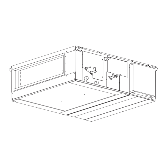
[ IX Disassembly Procedure ] IX Disassembly Procedure [1] Disassembly Procedure 1. Positions of major components Outlet Float switch/drain pump LEV/Pipe thermistor Inlet Control box Fan motor 2. Removing the service panel 1. To remove service panel A (Fig.1) (1) Remove the four service panel A fixing screws. Service panel B Service panel A Fig.1... -
Page 31: Control Box
[ IX Disassembly Procedure ] 3. Control box 1. To remove the control box cover (Fig.2) (1) Remove the two control box cover fixing screws. Control box cover Fig.2 (2) Removing the control box cover allows the following services to be performed. 1) Operating and checking the switches (See below) on the control box Rotary switch SW11,12 : ADDRESS SET Rotary switch SW14 : BRANCH NO. - Page 32 [ IX Disassembly Procedure ] Control board(I.B.) Power transformer (T) Terminal block for MA remote controller Auxiliary relay (X13) (TB15) Capacitor (C) Terminal block for (Fan motor) indoor-outdoor transmission line and M-NET remote controller cable (TB5) Power supply terminal block (TB2) Fig.3 Inside the control box (PEFY-AF1200CFM-E) Control board(I.B.2)
-
Page 33: Humidity Sensor/Lev/Pipe Thermistor
[ IX Disassembly Procedure ] 4. Humidity sensor/LEV/Pipe thermistor 1. According to the instructions provided in section 2-2, re- move service panel B. 2. According to the instructions provided in section 3-1, re- Humidity sensor move the control box cover. 3. -
Page 34: Drainpan
[ IX Disassembly Procedure ] 5. Drainpan 1. According to the instructions provided in section 2-1, re- move service panel A, and check for water inside. If the drain pan has water inside, drain the water through the drainage port. Protect the surrounding with a plastic sheet in case water spills out. -
Page 35: Pump/Float Switch/Supply Air Temperature Thermistor
[ IX Disassembly Procedure ] 6. Pump/float switch/supply air temperature thermistor 1. According to the instructions provided in section 2-1, re- move service panel A. 2. According to the instructions provided in section 3-1, re- move the control box cover. 3. -
Page 36: Fan And Fan Motor
[ IX Disassembly Procedure ] 7. Fan and fan motor Use caution not to pinch any wires. Use caution; the motor is heavy. 1. According to the instructions provided in section 3-1, re- move the control box cover. Sirocco fan 2. -
Page 37: Heat Exchanger
[ IX Disassembly Procedure ] 8. Heat exchanger This heat exchanger does not have a safety feature that prevents the internal parts from falling once removed. When removing parts, it is recommended that one person hold the parts to be removed while the another person un- screws the fixing screws to keep the parts from falling.