
Related Manuals for EVGA Z370 MICRO


Summary of Contents for EVGA Z370 MICRO
- Page 1 EVGA Z370 MICRO (121-KS-E375) User Guide EVGA Z370 MICRO Specs and Initial Installation - 1 -...
-
Page 2: Table Of Contents
Motherboard ......................- 6 - Motherboard Specifications ....................- 6 - Unpacking and Parts Descriptions ................- 8 - Intel Z370 Micro Motherboard LED reference ..............- 9 - ® Intel Z370 Micro Motherboard Component Legend............- 11 - ®... - Page 3 Have a question not covered above, or want some online resources? ......- 122 - POST Beep codes ......................- 123 - POST Port Debug LED ....................- 124 - EVGA Glossary of Terms ....................- 130 - Compliance Information ..................- 133 - - 3 -...
-
Page 4: Evga Z370 Micro
Dual-Band AC WiFi + BT; an M.2 Key-M slot and much more! ® Lastly, a motherboard is only as good as its BIOS, and the EVGA Z370 Micro features an updated UEFI/BIOS GUI with a focus on overclocking and functionality in a lean, straightforward package. You won’t need to be an expert to configure your motherboard, but if you are, you’ll find features unavailable... -
Page 5: Parts Not In The Kit
Monitor (Optional) Optical Drive EVGA assumes you have purchased all the necessary parts needed to allow for proper system functionality. For a full list of supported CPUs on this motherboard, please visit www.evga.com/support/motherboard Intentions of the Kit... -
Page 6: Motherboard
EVGA Z370 MICRO (121-KS-E375) Motherboard Motherboard Specifications Size: mATX form-factor of 9.6 inches x 9.6 inches (243.8x243.8mm) Microprocessor support: Intel Socket 1151 Processor ® Operating Systems: Supports Windows 10 64-Bit Contains Intel Z370 chipset ® System Memory support: ... - Page 7 EVGA Z370 MICRO (121-KS-E375) Onboard LAN: 1x Intel i219V Gigabit (10/100/1000) Ethernet PHY ® Onboard Audio: Realtek Audio (ALC1220) Supports 7.1 Channel HD Audio with Optical S/PDIF Out Power Functions: Supports ACPI (Advanced Configuration and Power Interface)
-
Page 8: Unpacking And Parts Descriptions
EVGA Z370 MICRO (121-KS-E375) Unpacking and Parts Descriptions The following accessories are included with the EVGA Z370 Micro Motherboard: - 8 -... -
Page 9: Intel ® Z370 Micro Motherboard Led Reference
EVGA Z370 MICRO (121-KS-E375) Intel Z370 Micro Motherboard LED reference ® The EVGA Z370 Micro Motherboard has several LEDs indicating power, connectivity, and activity. Below is the location of the LEDs and their function. - 9 -... - Page 10 EVGA Z370 MICRO (121-KS-E375) 1. CPU 12v. Error LED a. RED: Voltage failure. The LED will remain on when the motherboard detects an initialization failure in the CPU 12v. power connector. (This may be caused by a failure to connect an 8-pin ATX/EPS power connector, a power supply failure, or a failure with the CPU 12v.
-
Page 11: Intel ® Z370 Micro Motherboard Component Legend
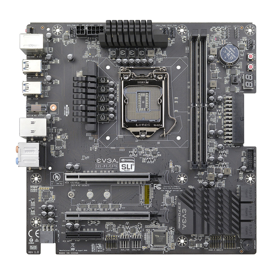
EVGA Z370 MICRO (121-KS-E375) Intel Z370 Micro Motherboard Component ® Legend The EVGA Z370 Micro Motherboard with the Intel Z370 and PCH Chipset. ® Figure 1 shows the motherboard and Figure 2 shows the back panel connectors. FIGURE 1. Z370 Micro Motherboard Layout... - Page 12 EVGA Z370 MICRO (121-KS-E375) Component Legend 1. CPU Socket 1151 10. M.2 Socket 3 Key-M 80mm 19. USB 2.0 Headers 2. Intel Z370 PCH (Southbridge) 11. PCI-E Slot x16/x8 20. Front Panel Audio Connector 3. PWM Fan Header (1 amp) 12.
- Page 13 EVGA Z370 MICRO (121-KS-E375) Figure 2. Chassis Rear Panel Connectors 3.5mm Audio Jack Legend Analog Audio Port 2/2.1 4.0/4.1 Breakdown Channel Channel Channel Channel Blue Line In Line In Line In * Rear Speakers Out Front Speakers Out / Front Speakers Out /...
- Page 14 2 stick kit of RAM. 32GB of RAM is supported in a 2x16GB configuration; 32GB modules are *NOT* officially supported. At the time of this manual’s release, the Z370 Micro officially supports up to 4133MHz+ speeds. These speeds cannot be...
- Page 15 POST and will hang at POST code “C.” 7. 4-pin Supplemental ATX Connector The ATX power connector on the Z370 Micro provides additional power to the CPU. This connector requires the appropriate 4-pin ATX power that is provided by your power supply – often as part of a 4+4-pin CPU connector.
- Page 16 EVGA Z370 MICRO (121-KS-E375) supports NCQ, TRIM, hot swap capability (provided the proper HDD/SSD bays/racks are installed), and RAID levels 0/1/5/10. 10. M.2 Socket 3 Key-M 80mm M.2 is an SSD form factor standard, which uses up to four PCIe lanes and utilizes Gen3 speeds.
- Page 17 EVGA Z370 MICRO (121-KS-E375) 14. RGB LED Controller Header The RBG header is a 4 pin header that allows a software based control within windows for RGB devices via ELEET-X. Please see Page 38 for control specifics. 15. Power Button This is an onboard power button, and may be used in place of, or in conjunction with, a front panel power button wired to the board.
- Page 18 USB2.0 header and uses the standard “HD Audio” jack. Some chassis may provide two headers: one labeled HD Audio, and one labeled AC’97 – an AC’97 cable is not compatible with this header on the Z370 Micro. 21. Front Panel Connectors The Front Panel Connectors are the four main chassis connections.
- Page 19 EVGA Z370 MICRO (121-KS-E375) 23. CMOS Battery The +3V CMOS battery backup provides uninterruptable power to the BIOS/UEFI to store all its settings; otherwise, each power on would act as if the BIOS was just reset. These batteries typically last several years and rarely need to be replaced.
- Page 20 EVGA Z370 MICRO (121-KS-E375) Card Slots The Z370 MICRO features two x16 PCIe slots, one x4 PCIe slot, one Socket 3 Key-M M.2 80mm (backwards compatible with Key-M 60mm, and 42mm), and one Socket 1 Key-E M.2. - 20 -...
-
Page 21: Pcie Slot Breakdown
EVGA Z370 MICRO (121-KS-E375) PCIe Slot Breakdown PCIe Lane Distribution (All Socket 1151 processors provide 16 lanes.) PE1 – x16 (Gen3, x16 lanes from CPU, x8 shared with PE2) PE2 – x16 (Gen3, x8 lanes from CPU, shares 8 of PE1’s 16 lanes) ... -
Page 22: Preparing The Motherboard
Preparing the Motherboard Installing the CPU Note: EVGA strongly recommends that you completely disconnect AC power from your power supply prior to changing your CPU. This ensures the motherboard will use the correct startup procedure for all onboard devices. If AC power is not disconnected, the replacement is still supported, but may require additional reboots to boot successfully. - Page 23 EVGA Z370 MICRO (121-KS-E375) 3. Align the notches on the CPU to the notches in the socket, and lower the processor straight down into the socket. Note: The gold triangle key on the CPU should match the triangle key on the socket cover.
-
Page 24: Installing The Cpu Cooling Device
EVGA Z370 MICRO (121-KS-E375) 5. Carefully lock the right lever back into place by lowering it down to the hook, then push the lever towards the socket and down under the hook. 6. Remove the plastic protective socket cover by pulling it straight up and away from the socket. -
Page 25: Installing System Memory (Dimms)
EVGA Z370 MICRO (121-KS-E375) Installing System Memory (DIMMs) Your Z370 Micro has (2) 288-pin slots for DDR4 memory. These slots support 4GB, 8GB and 16GB DDR4 DIMMs. There must be at least one memory slot populated for the board to boot and operate. -
Page 26: Installing The I/O Shield
EVGA Z370 MICRO (121-KS-E375) Installing the I/O Shield The motherboard kit comes with an I/O shield that is used to block internal components from dust and foreign objects, while also promoting correct airflow within the chassis. Before installing the motherboard, install the I/O shield from the inside of the chassis. -
Page 27: Securing The Motherboard Into A System Case
6. See the picture below for a zoomed-in view of a hole to place over a standoff, as well as the locations of standoff holes for the Z370 Micro. - 27 -... - Page 28 EVGA Z370 MICRO (121-KS-E375) 1. All safe locations to secure the board to a standoff are circled in white. 2. Keep in mind that when the screws are installed, but not fully tightened, the motherboard should have 1-2mm of movement; this can help when mounting cards or tight-fits with other components.
-
Page 29: Installing M.2 Devices
EVGA Z370 MICRO (121-KS-E375) Installing M.2 devices Securing an M.2 device to the motherboard requires a few extra steps compared to other current drive or slot-based connectors. M.2 devices used on this motherboard - Socket 3 (for SSDs) and Socket 1 (for WiFi/Bluetooth) – are installed and attached differently. - Page 30 EVGA Z370 MICRO (121-KS-E375) 3. Gently push the M.2 device down on the raised end. There will be some tension - this is normal - then use the screw you removed in Step 1 to secure the device. Below, you can see that the contacts will be nearly invisible when the device is properly seated and the copper mounting semi-circle is partially visible around the screw.
- Page 31 EVGA Z370 MICRO (121-KS-E375) Incorrect installation Example: *NOTE* This is one of the most common examples of an incorrect installation of an M.2 device. Do not intentionally attempt this, or complete your installation with this example. Doing so could cause damage to the device or the M.2 port.
-
Page 32: Tested Cpu
EVGA Z370 MICRO (121-KS-E375) Tested CPU Tested Memory For a full list of tested CPUs and Memory, please visit https://www.evga.com/support/motherboard/ and select the EVGA Z370 Micro from the list. - 32 -... -
Page 33: Tested M.2 Key-M
EVGA Z370 MICRO (121-KS-E375) Tested M.2 Key-M Tested M.2 Key-E - 33 -... -
Page 34: Connecting Cables
Connecting Cables Note: the following images do not necessarily represent the physical orientation of their respective headers on the EVGA Z370 MICRO. Instead, these graphical representations are designed to provide a basic physical footprint and the cable pinouts for each component. - Page 35 The 24-pin Power Connector may be standard or right-angled depending on your motherboard model. The Z370 Micro motherboard uses a horizontal, right-angle 24-pin ATX connector. - 35 -...
- Page 36 EVGA Z370 MICRO (121-KS-E375) EPS 8-pin 12V Power (PWR , the 8-pin ATX 12V power connection, is used to EPS PWR 8P (REQUIRED) provide power to the CPU. Align the pins to the connector and press firmly until seated. Please remember to make sure that the tab on the EPS socket is aligned with the release clip on the cable.
- Page 37 EVGA Z370 MICRO (121-KS-E375) Front Panel Header The front panel header on this motherboard is used to connect the following four cables: PWRLED Attach the front panel power LED cable to these two pins of the connector. The Power LED indicates the system’s status. When the system is powered on, the LED will be on.
- Page 38 EVGA Z370 MICRO (121-KS-E375) RBG LED Header This header and pinout is also shared with the RGB LED header, which also supports 1 Amp @ 12 Volts (12 Watts). This will add control options through EleetX for controlling RGB LED’s.
- Page 39 EVGA Z370 MICRO (121-KS-E375) PWM Fan Header This motherboard line only has 4-pin PWM fan headers, which are backwards compatible with 3-pin fan connectors. Fans may be controlled by PWM or DC controls. The headers have an absolute safe power limit of 1 Amp @ 12 Volts (12 Watts).
- Page 40 EVGA Z370 MICRO (121-KS-E375) USB Headers This motherboard contains USB 3.0 and USB 2.0 ports located on the rear panel of the chassis. The motherboard contains 1x 19-pin internal header connectors onboard that can be used to connect up to two (2) USB 3.0 ports, such as front panel cables included with your chassis.
- Page 41 The motherboard contains 1x 9-pin internal header connectors onboard that can be used to connect up to two (2) USB 2.0 ports, such as front panel cables provided with your chassis or AIO liquid coolers (e.g. EVGA CLC Coolers). - 41 -...
- Page 42 Front panel audio connectors support different audio standards and can provide two kinds of audio output choices: HD Audio, or AC’97 to accommodate older cases that still use AC’97, rather than HD. The Z370 Micro only has a HD Audio front panel connector.
- Page 43 PCIe slots, rather than pulling it all from the 24-pin main power. EVGA strongly recommends plugging in this connector for 3-way, 4- way, and Quad SLI, regardless of GPU. Although the Z370 Micro does not support 3-way or 4-way SLI, connecting a 6-pin PCIe connector is still...
- Page 44 EVGA Z370 MICRO (121-KS-E375) Drive Headers (SATA) SATA3/6Gbit/s is the current standard for HDD/SSD/Optical interface. These cables are the data interconnect for the motherboard. Your HDD/SSD/Optical interface will still require a separate power connection from your power supply. SATA ports on this platform natively support full AHCI and RAID functions.
-
Page 45: Onboard Buttons
EVGA Z370 MICRO (121-KS-E375) Onboard Buttons These onboard buttons include RESET, POWER and Clear CMOS. These functions allow you to easily turn on/off the system, reset the system, or clear the CMOS. Clear CMOS Button The motherboard uses CMOS RAM to store set parameters. -
Page 46: First Boot
EVGA Z370 MICRO (121-KS-E375) First Boot BIOS Update When you power on the system for the first time (or after a BIOS update/reset) it may take a little longer than expected, and follow with a pause and message on the screen reading “BIOS Checksum error, Press F2 to continue or F12 to enter the BIOS.”... - Page 47 EVGA Z370 MICRO (121-KS-E375) HDD/SSD/M.2 Setup Next, click “Boot” from the menu list at the top. “Boot Option #1” should show the device that you intend to install your operating system. If you are using a standard SSD/HDD connected to a SATA port, but the device is not present in the Boot Option #1 menu, scroll down to “UEFI Hard...
-
Page 48: Ssd, Pcie Ssd, And Nvme Ssd Installation Steps
EVGA Z370 MICRO (121-KS-E375) M.2 SSD, PCIe SSD, and NVMe SSD Installation steps M.2 is a versatile card module form factor that uses multiple connecter types to connect many types of devices, such as WiFi or SSDs, in a very small and power efficient package. - Page 49 EVGA Z370 MICRO (121-KS-E375) 2. After reviewing your SSD’s instructions and its respective Physical installation instructions above, power on the PC and enter the BIOS/UEFI by pressing the F2 key repeatedly. 3. Once in BIOS/UEFI, navigate to the “BOOT” section. Then go down to the “CSM Configuration”...
-
Page 50: Internal Raid Controller
EVGA Z370 MICRO (121-KS-E375) Internal RAID Controller This section introduces RAID, RAID levels, and the basics of the controller integrated into the PCH. It covers the basics of what RAID does, how RAID works, and why you may or may not want to use RAID. - Page 51 EVGA Z370 MICRO (121-KS-E375) its quality, and many other factors; but the number should give you a ballpark estimate on what to expect as a final capacity once formatted. Please see below for examples of what to expect when you build an array of each type.
- Page 52 EVGA Z370 MICRO (121-KS-E375) one drive fails, the array fails. It MAY be possible to recover the data but that usually requires a data recovery service, which is not guaranteed and is usually very expensive. RAID0 is typically only limited by the controller; however, you will get severely diminishing performance returns after 4 drives.
- Page 53 EVGA Z370 MICRO (121-KS-E375) RAID 0 (4 Drive) P-DRIVE1 P-DRIVE2 P-DRIVE3 P-DRIVE4 P-DRIVE1 P-DRIVE2 P-DRIVE3 P-DRIVE4 DATA-A DATA-B DATA-C DATA-D DATA-A DATA-B DATA-C DATA-D DATA-ABCD DATA-ABCD P-DRIVE1 P-DRIVE2 P-DRIVE3 P-DRIVE4 P-DRIVE1 P-DRIVE2 P-DRIVE3 P-DRIVE4 DATA-A DATA-B DATA-C DATA-D DATA-A DATA-B...
- Page 54 EVGA Z370 MICRO (121-KS-E375) The Bad- RAID1 is not a storage capacity-friendly array, because the capacity will be limited to 1 drive. o Due to the capacity available on modern drive solutions, this issue may not be as significant as it once was.
- Page 55 EVGA Z370 MICRO (121-KS-E375) rebuild process, performance will be severely degraded and can take several hours, depending on the size of the array and percentage of capacity used. The Good- Most space efficient array-type that also has fault tolerance.
- Page 56 EVGA Z370 MICRO (121-KS-E375) L-DRIVE = ≃ 3TB RAID 5 (4 Drive) P-DRIVE1 P-DRIVE2 P-DRIVE3 P-DRIVE4 P-DRIVE1 P-DRIVE2 P-DRIVE3 P-DRIVE4 P-DRIVE1 P-DRIVE2 P-DRIVE3 P-DRIVE4 DATA-A DATA-B DATA-C DATA-A DATA-A DATA-B DATA-C DATA-A DATA-A DATA-B DATA-C DATA-A DATA-B DATA-C DATA-A DATA-B...
- Page 57 L-Drive = DATA-AB L-Drive = DATA-AB While the Z370 MICRO controller will support a four or six drive RAID10 array, RAID10 can scale indefinitely provided the controller supports more drives. Every pair of drives adds an additional mirrored node, which increases the theoretical number of failures the array can suffer before a loss of data occurs.
- Page 58 EVGA Z370 MICRO (121-KS-E375) In the case of a drive RAID 10 (6 Drive) L-DRIVE = ≃ 3TB failure, the array controller P-DRIVE1 P-DRIVE2 P-DRIVE3 P-DRIVE4 P-DRIVE5 P-DRIVE6 will notify you. When you replace a failed drive in the P-DATA-A P-DATA-A...
- Page 59 EVGA Z370 MICRO (121-KS-E375) RAID0+1 : RAID0+1 is a form of nested RAID that was widely used on previous generation boards. Although the Z370 Series motherboards do not use this type of array, it is listed here to show the improvements made by RAID10, and to clear up a common misperception that RAID0+1 and RAID10 are the same.
- Page 60 L-Drive = DATA-AB L-Drive = DATA-AB Motherboard controllers that support RAID0+1 (such as on older generation EVGA motherboards) will generally support 4 or 6 drive arrays of this type; other controllers can allow this array type to scale indefinitely. Each pair of drives adds to the drive count for the stripes and increases the theoretical volume of failures the array can suffer before a loss of data occurs.
- Page 61 EVGA Z370 MICRO (121-KS-E375) As you can see, the RAID 0+1 (6 Drive) L-DRIVE = ≃ 3TB difference between RAID0+1 and RAID10 is P-DRIVE1 P-DRIVE2 P-DRIVE3 P-DRIVE4 P-DRIVE5 P-DRIVE6 significant when looking at DATA-A DATA-B DATA-C DATA-A DATA-B DATA-C how data is stored.
- Page 62 EVGA Z370 MICRO (121-KS-E375) Which types of RAID can I use with my setup? 1 Drive – No RAID arrays are supported 2 Drives – RAID0 for speed (do regular backups) or RAID1 for data protection. 3 Drives – RAID0 for speed (do regular backups) or RAID5 for speed and protection.
- Page 63 EVGA Z370 MICRO (121-KS-E375) RAID mode not only includes the RAID controls, but also shares the same options/functions/commands as AHCI; you may continue using your AHCI devices normally when the SATA Configuration is set to RAID mode. The SATA Information menu shows a list of all drives currently detected by the controller;...
- Page 64 EVGA Z370 MICRO (121-KS-E375) Once in the RAID controller, you will see a list of all detected drives and a “Create RAID Volume” button. To begin, click on “Create RAID Volume” or navigate to the button and hit “Enter.” Choose a name for the volume. The controller allows up to 15 characters; you can use numbers and letters, but not special characters.
- Page 65 EVGA Z370 MICRO (121-KS-E375) Next, select your intended array type. This can be done by either clicking on the down arrow and clicking on the RAID level you want, or pressing the enter key and using the down arrow to select the RAID level and pressing Enter again. Please see the top half of Page 62 for a quick reference on different RAID levels and RAID types based on your total number of drives.
- Page 66 EVGA Z370 MICRO (121-KS-E375) Strip size (also called “block size” in other controllers) can be selected manually at 16k, 32k, 64k, or 128k. The controller will determine the default strip size after looking at your drives and array type. Although there are some limited instances where this must be set manually, it is highly recommended to leave this at default.
- Page 67 EVGA Z370 MICRO (121-KS-E375) If your array will be your boot drive, the operating system will normally detect the array and see it as a single drive (this is expected), it *MAY* detect it as a RAID array; either way, the OS installation will show the size of the array, not a single drive, and allow you to install the OS to the array without any further steps.
- Page 68 EVGA Z370 MICRO (121-KS-E375) Non-RAID Physical Disks list will display any remaining drives on the controller, whether it is a random storage drive, a boot drive, or a replacement drive installed to replace a failed unit. For this example, you will see a degraded array and a “Non-RAID Physical Disk,”...
- Page 69 EVGA Z370 MICRO (121-KS-E375) Next, you will see a list of all attached HDD/SSDs that can be used to rebuild the array. Select the disk, then click on it or press enter. Once the process has started you will see the status change to “Rebuilding.”...
- Page 70 EVGA Z370 MICRO (121-KS-E375) IRST (Intel ® Rapid Storage Technology) The IRST is the software front-end for the Intel SATA controller. It is recommended ® to install the IRST drivers after installing the Intel Chipset Drivers – the main ®...
- Page 71 EVGA Z370 MICRO (121-KS-E375) SATA will be selected by default. PCIe primarily refers to PCIe / M.2 based NVMe drives; the same basic steps do apply to both, however. Select SATA, and “Real-time protection (RAID1).” Then, click Next at the bottom of the window.
- Page 72 EVGA Z370 MICRO (121-KS-E375) - 72 -...
- Page 73 EVGA Z370 MICRO (121-KS-E375) In the Advanced tab, you can select the option to “Initialize Volume,” which will occur after the array is created. If the array is not initialized now, it can be initialized later in “Disk Management.” See Page 80 for Disk Management instructions.
- Page 74 EVGA Z370 MICRO (121-KS-E375) Review the summary provided on the confirmation screen. If you are unsure about any selections made, click the “Back” key and make your corrections. When ready, click “Create Volume” at the bottom. This typically takes between a few seconds to a couple minutes depending on the size and complexity of the volume.
- Page 75 EVGA Z370 MICRO (121-KS-E375) Once you click the OK button on the RAID creation window you will be brought back to the main window, “Status” tab. If the option to initialize was selected, the initialization status will be shown below, circled in red.
- Page 76 EVGA Z370 MICRO (121-KS-E375) Repairing an array within IRST This section of the guide will illustrate how to repair a degraded array from within the IRST. For purposes of this guide, we are repairing a degraded RAID 1 array using a third drive plugged into the controller, but not currently in use.
- Page 77 EVGA Z370 MICRO (121-KS-E375) The “Manage” tab shows the array specifically, and not just the controller as a whole. Next to “Status: Degraded,” left-click the hyperlink labeled “Rebuild to another disk.” This will bring a pop-up window over the IRST showing a list of attached drives that...
- Page 78 EVGA Z370 MICRO (121-KS-E375) Select the drive you wish to use for the repair and click the “Rebuild” button. - 78 -...
- Page 79 EVGA Z370 MICRO (121-KS-E375) The rebuild process will begin. As with any RAID array with Fault Tolerance, the rebuilding time depends on several factors, such as array size, array type, CPU, etc. You will then see the Rebuild % status in the Manage tab. Once repairs are complete, the array will update to “Status: Normal.”...
- Page 80 EVGA Z370 MICRO (121-KS-E375) Partitioning and Formatting a drive Once you have created your array, either from UEFI or from IRST, you will not initially see your array in “This PC.” This is expected, because even though you have created the array, you have not yet prepared the array to be used.
- Page 81 EVGA Z370 MICRO (121-KS-E375) After “Disk Management” loads, you’ll see a pop-up to Initialize Disk if you’ve added a new drive or created a new array. Generally, it’s recommended to select “GPT,” unless you need backwards compatibility with an old OS or PC. When you’ve made your choice, click “OK.”...
- Page 82 EVGA Z370 MICRO (121-KS-E375) Before you can assign a drive letter to a drive or array, the initialized disk must be partitioned. If you are following this guide and just initialized your drive or array, the New Simple Volume Wizard will automatically pop-up.
- Page 83 EVGA Z370 MICRO (121-KS-E375) Leave the size at default to create a partition using the entire volume of disk space, then click “Next.” Select the drive letter you want to represent this drive, then click “Next.” Note: The drive letter does NOT have to be a consecutive letter with previous drive(s).
- Page 84 EVGA Z370 MICRO (121-KS-E375) After the quick format is completed, you will see the last Window of the wizard, a summary of the process, then click “Finish.” The drive is now usable. To confirm, go back to File Explorer in Windows. Click on “This PC” and check the drives section.
-
Page 85: Fan Header And Pwm Setup
EVGA Z370 MICRO (121-KS-E375) Fan Header and PWM Setup The Z370 Micro supports both 4-pin PWM fans and 3-pin voltage-controlled fans. The motherboard uses six 4-pin PWM fan headers, including 2x CPU FAN, a CHA FAN, a PWR FAN, a SYS FAN, and a AUX FAN. All fans can be controlled by either DC (Direct Current) or PWM. - Page 86 EVGA Z370 MICRO (121-KS-E375) Once into the H/W Monitor section, you can see the temperature monitors across the top. Below the monitors are the three (3) Smart Fans: CPU1_FAN, CPU2_FAN, and CHA_FAN. These fans are set to “Smart,” which means the controller is using a Smart curve for fan controls.
- Page 87 EVGA Z370 MICRO (121-KS-E375) To set a Smart curve, select the “Smart Fan Settings” and enter the menu. First, choose the temperature monitor the PWM controller will use to monitor for its temp information. It’s recommended to link the fan control to the CPU, which is predominantly the most important temperature in the system.
- Page 88 When monitoring temperatures vs. fan speed, you may notice a variance in ramp up/down temps; this is due to a function EVGA hardcodes into the BIOS called Hysteresis. Hysteresis builds in a buffer to control fan speed behavior. This feature prevents a constant ramp up/down from happening when your system sits exactly at the temp you set for SMART fan controls.
-
Page 89: Setting Up Sli And Physx
1. Physically install your graphics cards, then install an SLI bridge; examples include a Flexible bridge (included with this motherboard), an EVGA Pro Bridge, or an EVGA HB Bridge. Current NVidia graphics drivers support 400 Series Fermi cards up through GTX 1080 Ti and Titan XP cards. - Page 90 EVGA Z370 MICRO (121-KS-E375) 2. After the cards are installed, have power connected, and the SLI bridge attached, boot into Windows. The graphics driver will normally identify the cards and automatically configure the driver. If not, then you may need to reinstall the driver.
- Page 91 EVGA Z370 MICRO (121-KS-E375) 3. Once you have verified there are no detection/driver installation issues with the cards you can enable SLI. Right-click on the desktop and select “NVIDIA Control Panel” (“NCP”). Next, select “Configure SLI, Surround, PhysX” under the “3D Settings”...
- Page 92 PhysX card serves no purpose. If “Yes,” then the next step is to see if your GPU has a high usage rate while playing normally. Use a program like EVGA Precision XOC to monitor the GPU usage of all current video cards. If the GPU is consistently over 75% usage, the GPU usage occasionally maxes out and the frame rate drops in moments of intense action, then dedicating a card may be beneficial.
-
Page 93: Realtek Hd Audio Manager
EVGA Z370 MICRO (121-KS-E375) Realtek HD Audio Manager The Z370 Micro uses a 7.1 Realtek ALC1220 audio controller. This section will cover installation of the controller (in Windows 10) and the basic configuration options that are available in the software. - Page 94 EVGA Z370 MICRO (121-KS-E375) Once you have rebooted and re-entered Windows, there should be a new shortcut in the system tray with a red- orange speaker icon. When you mouse over it, the icon reads “Realtek HD Audio Manager.” When the menu opens, left-click on it, and left-click the similar red-orange speaker icon labeled “Sound Manager”...
- Page 95 EVGA Z370 MICRO (121-KS-E375) On the right margin, you can see the different ports labeled in the picture above. The top portion covers the five (5) analog ports on the I/O Hub. The two (2) labeled “Speaker Out” ports and “Line In” port all use a diffused color to show that a port is not currently connected;...
- Page 96 EVGA Z370 MICRO (121-KS-E375) component number 8, respectively. The optical out contains all audio data the controller can provide; however, only 2.0/2.1 is pre-encoded from the controller. Audio with a higher channel count through optical S/PDIF must be connected to a receiver that supports live encoding, or an equivalent technology.
- Page 97 EVGA Z370 MICRO (121-KS-E375) The icon of the file folder in the upper right is “Connector Settings.” This is the window for setting up port detection. The default setting in this Window allows the Manager to create a popup notification to let you know when you’ve plugged in a new device into a Realtek port(s) while Windows is running.
- Page 98 EVGA Z370 MICRO (121-KS-E375) The “i” located at the bottom right of the Manager is an information button. Clicking on this will provide DirectX information, the CODEC and Language selection options. The main page defaults to the first audio device it detects;...
- Page 99 EVGA Z370 MICRO (121-KS-E375) To the right of the pulldown is the Restore Defaults button, shown by an eraser icon, which will reset any changes made to the default of the controller. If you switch over to the Sound Effects tab, you’ll notice the “Main Volume” controls near the top.
- Page 100 EVGA Z370 MICRO (121-KS-E375) The “Set Default Device” will allow you to set the Default Device or Communication Device without entering the Windows Playback menu; for non-default devices, this box will drop down similar to the image above. For default devices, the box will be grayed- out if the device selected above (i.e.
- Page 101 EVGA Z370 MICRO (121-KS-E375) source. This is unchecked by default. There is no additional configuration; the setting is either enabled or disabled. The last section in Sound Effects is the Equalizer. Much like the environment section, there are visual references for presets, a...
- Page 102 EVGA Z370 MICRO (121-KS-E375) If you would prefer to not manage the EQ in full manual mode, you can click the guitar icon with the red box around it to bring you back to the equalizer presets menu. The last section in Sound Effects is voice cancellation,...
- Page 103 EVGA Z370 MICRO (121-KS-E375) The “Audio Test” button will be present for all speaker configurations, and serves the same function in all speaker iterations. Pressing the “Auto Test” button will play the same sound file out of each speaker that should be present, based on the configuration option you selected.
- Page 104 EVGA Z370 MICRO (121-KS-E375) • Assume your speakers are not full-range. Modern speaker design uses a subwoofer to handle the relatively small percentage of content you hear in an audio signal. Low frequency content, more commonly known as sub-bass, is greatly amplified by the subwoofer, which explains why the smallest percentage of your audio content can often be the loudest.
- Page 105 EVGA Z370 MICRO (121-KS-E375) crossover at the receiver or speaker system, rather than using the Audio Manager to configure the crossover settings for low frequencies. When Full-range is enabled, the speaker icons are enlarged to represent the change. Finally, Virtual Sound is an option created to send a stereo signal with positioning data to a Matrix decoder to simulate surround over a stereo signal.
- Page 106 EVGA Z370 MICRO (121-KS-E375) this setting. Also, most surround speaker sets use both the front pair and subwoofer on the same channel and voice speaker on a separate channel; in some instances, this is reversed such that the voice channel is joined with the front pair on one channel and the subwoofer has a dedicated connector, which can lead to voice channels and subwoofer receiving the wrong signal.
- Page 107 Windows. Due to the advanced nature of editing the Windows registry, we do not provide instructions in this manual. However, if you would like to adjust the crossover frequency settings, please see our FAQ on the EVGA website to walk you through how to adjust this setting: http://www.evga.com/support/faq/?f=59663.
- Page 108 EVGA Z370 MICRO (121-KS-E375) right if you open the “Room Correction” tab in Quadraphonic or Stereo mode. If 5.1 or 7.1 is installed and setup in the “Speaker Configuration” page, you will see the full Room Correction menu without an error message. All speakers will initially show semi- transparently.
- Page 109 EVGA Z370 MICRO (121-KS-E375) The final Device section covers the microphone. This tab includes both a recording and a playback section. Both features have similar balance options as the other sections, but differ slightly in the Volume slider function. The Recording...
- Page 110 EVGA Z370 MICRO (121-KS-E375) Under “Microphone Effects,” there are two options that may be enabled: “Noise Suppression” and “Acoustic Echo Cancellation.” “Noise Suppression” helps to remove background noises, such as fans, air conditioning, or anything else that causes a consistent ambient sound in the room.
- Page 111 EVGA Z370 MICRO (121-KS-E375) Using the E-LEET Software Suite EVGA E-LEET is a monitoring and tuning software designed for EVGA motherboards, which is available on the driver DVD and the EVGA website at www.evga.com/E-LEET After installation, E-LEET will launch directly...
- Page 112 EVGA Z370 MICRO (121-KS-E375) The next tab is “Monitoring,” which is an overview of temperatures and voltages in real- time. Please note that all readings on this page are pulled from motherboard sensors, and can change at any time. Temperatures and voltages...
- Page 113 EVGA Z370 MICRO (121-KS-E375) The Options tab is for managing your E- LEET profiles. You can save overclock profiles made in the previous section, as well as selecting an option to load a profile at boot. Use care, however, when setting a profile to load on startup;...
- Page 114 EVGA Z370 MICRO (121-KS-E375) The final section is “Voltages,” which provides a level of voltage control similar to what is available in the BIOS. Using the right image, you’ll notice that there are options for multiple voltages, and two options for your CPU Vcore: Adaptive and Override voltages.
- Page 115 LEET will open the pulldown to the currently detected voltage. Please be careful when adjusting voltages, as there are risks to running electronics out of spec. Although EVGA warranties overclocking, other components are manufactured by different brands (i.e. RAM and CPU), which may have different policies towards overclocking.
-
Page 116: Installing Drivers And Software
User’s Manual Windows 10 Driver Installation 1. Insert the EVGA Z370 installation DVD for the motherboard included in the kit. 2. The DVD will auto-run. Install the drivers and utilities listed on the install screen. If the DVD does not run, go to My Computer and click on the CD to open. -
Page 117: Warranty And Overclocking
Of course, there are some limitations to our warranties. If an EVGA motherboard or graphics card sustains physical (i.e. damage to the PCB or component due to slippage with a hand tool) or liquid damage, the warranty is void. -
Page 118: Troubleshooting
EVGA Z370 MICRO (121-KS-E375) Troubleshooting SSD / HDD is not detected It is important to note that, as with *ALL* storage devices, if there is a connectivity issue, make sure it is enabled in BIOS. Likewise, if there is a device that shares bandwidth with your SSD or HDD (Page 21), make sure that the desired device is enabled in BIOS, or all other troubleshooting that comes after this section is moot. - Page 119 EVGA Z370 MICRO (121-KS-E375) connector that shares its bandwidth, you will need to check and/or change the BIOS setting related to your device. If you’ve already checked the cables and confirmed the port is not sharing bandwidth, test a different device using the same cable and SATA port to see if the issue persists. If the issue is not resolved, test a different SATA cable, or a different SATA port.
-
Page 120: System Does Not Post, And Post Code Indicator Reads "C
EVGA Z370 MICRO (121-KS-E375) System does not POST, and POST code indicator reads “C” When the system powers on, the POST code indicator should cycle through several different codes before booting. However, if the boot process does not complete, you should look at the LED indicator, as it will give you diagnostic information. -
Page 121: System Does Not Post, And Post Code Indicator Reads "55" Or "B7
Make sure that the memory is on the official support list at www.evga.com/support/motherboard and click on “EVGA Z370 Micro.” If the memory is not on the list, it may still work because EVGA is unable to test every memory kit released. However, this motherboard will not support modules over 16GB or ECC/Registered RAM. -
Page 122: Have A Question Not Covered Above, Or Want Some Online Resources
YOUR system! Still building your rig? Make a build log here: http://forums.evga.com/EVGA-MODS-RIGS-f33.aspx Want to join the online EVGA Gaming Community? Sign up and play with like-minded gamers here: http://www.evga.com/TEAMEVGA/ - 122 -... -
Page 123: Post Beep Codes
EVGA Z370 MICRO (121-KS-E375) POST Beep codes POST beeps are used in conjunction with the POST Code indicator to help determine the root cause when your system fails to boot. However, modern UEFI/BIOS motherboards also use the speaker to convey helpful information, such as USB device detection. -
Page 124: Post Port Debug Led
EVGA Z370 MICRO (121-KS-E375) POST Port Debug LED Provides two-digit diagnostic POST codes that shows system boot status and can also show why the system may be failing to boot. The LED is extremely useful during troubleshooting situations. This Debug LED will display a series of hexadecimal (0-F) codes during the POST and will display current CPU socket temperatures after the system has fully booted into the Operating System. - Page 125 EVGA Z370 MICRO (121-KS-E375) POST Codes This section provides the AMI POST Codes for the EVGA Z370 Micro Motherboard during system boot up. The POST Codes are displayed on the Debug LED readout located directly on the motherboard. See Pages 11 and 12, component 17 of the Component...
- Page 126 EVGA Z370 MICRO (121-KS-E375) Microcode not loaded PEI Core is started 11-14 Pre-memory CPU initialization is started 15-18 Pre-memory North Bridge initialization is started 19-1C Pre-memory South Bridge initialization is started 1D-2A OEM pre-memory initialization codes Memory initialization. Serial Presence Detect (SPD) data reading Memory initialization.
- Page 127 EVGA Z370 MICRO (121-KS-E375) reset PPI is not available 5C-5F Reserved for future AMI error codes S3 Resume is stared (S3 Resume PPI is called by the DXE IPL) S3 Boot Script execution Video repost OS S3 wake vector call...
- Page 128 EVGA Z370 MICRO (121-KS-E375) CSM initialization 7A–7F Reserved for future AMI DXE codes 80–8F OEM DXE initialization codes Boot Device Selection (BDS) phase is started Driver connecting is started PCI Bus initialization is started PCI Bus Hot Plug Controller Initialization...
- Page 129 EVGA Z370 MICRO (121-KS-E375) Legacy Boot event Exit Boot Services event CPU Memory controller configuration Runtime Set Virtual Address MAP End iMC init Memory training Memory training Memory training / timing training Memory training Memory training B8-BF Memory training / DRAM final configuration C0–CF OEM BDS initialization codes...
-
Page 130: Evga Glossary Of Terms
DMI – Direct Memory Interface DP – Display Port DRAM - Dynamic random access memory DVI – Digital Video Interface E-LEET X – EVGA motherboard monitoring and tuning software FIVR – Fully Integrated Voltage Regulator GHz – Gigahertz GPU – Graphics Processing Unit GUI –... - Page 131 EVGA Z370 MICRO (121-KS-E375) IEEE - Institute of Electrical and Electronics Engineers IGP - Integrated Graphics Processors IMC – Integrated memory controller IOH – Input/Output Hub IRQ - Interrupt Request JBOD - Just a Bunch of Disks JEDEC - Joint Electron Device Engineering Council...
- Page 132 EVGA Z370 MICRO (121-KS-E375) PLL – Phase Locked Loop POST – Power on Self-Test PWM – Pulse Width Modulation QDR - Quad Data Rate QOS – Quality of Service QPI – Quick Path Interconnect RAID - Redundant Array of Inexpensive Disks RAM –...
-
Page 133: Compliance Information
US and other countries. Other company, products and service names may be trademarks or service marks of others. EVGA reserves the right to terminate this license if there is a violation of its terms or default by the Original Purchaser. Upon termination, for any reason, all copies of Software and materials must be immediately returned to EVGA and the Original Purchaser shall be liable to EVGA.com...
Need help?
Do you have a question about the Z370 MICRO and is the answer not in the manual?
Questions and answers