Table of Contents
Advertisement
Quick Links
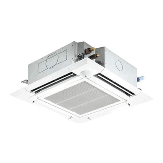
INDOOR UNIT FOR VRF SYSTEM
TECHNICAL & SERVICE MANUAL
Indoor unit
[Model Name]
TPLFYP006EM140A
TPLFYP008EM140A
TPLFYP012EM140A
TPLFYP015EM140A
TPLFYP018EM141A
TPLFYP024EM140A
TPLFYP030EM140A
TPLFYP036EM140A
TPLFYP048EM140A
Grille model
[Model Name]
TLP-40EAEU
TLP-41EAEU
Model name
indication for
INDOOR UNIT
MAIN UNIT
ON/OFF
TEMP
IR WIRELESS REMOTE
CONTROLLER
(Option)
Model name
indication for GRILLE
ON
RETURN SELECT
MENU
HOLD
OFF
WIRED REMOTE
CONTROLLER
(Option)
No. OCHT610
REVISED EDITION-B
R410A
Notes:
• 5.OUTLINES AND
DIMENSIONS has been
revised.
• Some descriptions
have been modified in
REVISED-EDITION-B.
OCHT610 REVISED
EDITION-A is void.
CONTENTS
1. SAFETY PRECAUTION .......................... 2
2. PARTS NAMES AND FUNCTIONS ........ 4
3. SPECIFICATIONS ................................. 12
4. 4-WAY AIRFLOW SYSTEM .................. 18
5. OUTLINES AND DIMENSIONS ............ 21
6. WIRING DIAGRAM ............................... 22
7. REFRIGERANT SYSTEM DIAGRAM ...... 23
8. MICROPROCESSOR CONTROL ......... 24
9. TROUBLESHOOTING .......................... 31
10. DISASSEMBLY PROCEDURE ........... 39
PARTS CATALOG (OCBT610)
August 2020
Advertisement
Table of Contents

Related Manuals for Mitsubishi Electric TRANE CITY MULTI Series


Summary of Contents for Mitsubishi Electric TRANE CITY MULTI Series
-
Page 1: Table Of Contents
INDOOR UNIT FOR VRF SYSTEM August 2020 No. OCHT610 TECHNICAL & SERVICE MANUAL REVISED EDITION-B R410A Indoor unit [Model Name] Notes: • 5.OUTLINES AND TPLFYP006EM140A DIMENSIONS has been TPLFYP008EM140A revised. • Some descriptions TPLFYP012EM140A have been modified in REVISED-EDITION-B. TPLFYP015EM140A TPLFYP018EM141A OCHT610 REVISED EDITION-A is void. -
Page 2: Safety Precaution
SAFETY PRECAUTION CAUTIONS RELATED TO NEW REFRIGERANT Cautions for units utilizing refrigerant R410A Use the following tools specifically designed for Do not use the existing refrigerant piping. use with R410A refrigerant. The old refrigerant and lubricant in the existing piping The following tools are necessary to use R410A refrigerant. - Page 3 [1] Cautions for service (1) Perform service after recovering the refrigerant left in unit completely. (2) Do not release refrigerant in the air. (3) After completing service, charge the cycle with specified amount of refrigerant. (4) When performing service, install a filter drier simultaneously. Be sure to use a filter drier for new refrigerant.
-
Page 4: Parts Names And Functions
PARTS NAMES AND FUNCTIONS 2-1. Indoor Unit Drain pipe Filter Air outlet Liquid pipe Gas pipe i-See sensor Vane Air intake (Intake grille) 2-2. Wired Remote Controller <TAR-40MAA> <TAC-YT53CRAU> Wired remote controller function The functions which can be used are restricted according to each model. : Supported : Unsupported TAR-40MAA... - Page 5 2-2-1. Wired Remote Controller <TAR-40MAA> Controller interface The functions of the function buttons change depending on the screen. Refer to the button function guide that appears at the bottom of the LCD for the functions they serve on a given screen. When the system is centrally controlled, the button function guide that corresponds to the locked button will not appear.
- Page 6 Display The main display can be displayed in two different modes: “Full” and “Basic”. The factory setting is “Full”. To switch to the “Basic” mode, change the setting on the Main display setting. (Refer to operation manual included with remote controller.) <Full mode>...
- Page 7 Main menu Operation Vane · Louver · Vent. (Lossnay) High power Comfort Manual vane angle 3D i-See sensor Timer menu Timer ON/OFF timer Auto-OFF timer Weekly timer OU silent mode Energy saving Restriction Temp. range Operation locked Energy saving Auto return Schedule Initial setting menu Basic setting...
- Page 8 Continue from the previous page. Maintenance menu Error information Filter information Cleaning Auto descending panel Descending operation Descending adjustment Service menu Test run menu Test run Drain pump test run Maintenance information Model name input Serial No. input Dealer information input Initialize maintenance info.
- Page 9 Main menu list Main Setting and display items Setting details menu Operation Vane · Louver · Vent. Use to set the vane angle. (Lossnay) • Select a desired vane setting from 5 different settings. Use to turn ON/OFF the louver. •...
- Page 10 Main Setting and display items Setting details menu Initial Basic Main/Sub When connecting 2 remote controllers, one of them needs to be designated as setting setting a sub controller. Clock Use to set the current time. Daylight Set the daylight saving time. saving time Administrator The administrator password is required to make the settings for the following...
- Page 11 2-2-2. Wired Remote Controller <TAC-YT53CRAU> Note: The phrase "Wired remote controller" in this manual refers only to the TAC-YT53CRAU. If you need any information for the other remote controller, please refer to either the installation manual or initial setting manual which are included in remote controller's box.
-
Page 12: Specifications
SPECIFICATIONS 3-1. SPECIFICATIONS Service Ref. TPLFYP006EM140A TPLFYP008EM140A TPLFYP012EM140A TPLFYP015EM140A Power source 1-Phase 208–230 V, 60 HZ Cooling capacity Btu/h 6,000 8,000 12,000 15,000 (Nominal) Power input 0.02 0.03 Current input 0.19 0.31 Heating capacity Btu/h 6,700 9,000 13,500 17,000 (Nominal) Power input 0.02 Current input... - Page 13 Service Ref. TPLFYP018EM141A TPLFYP024EM140A TPLFYP030EM140A Power source 1-Phase 208–230 V, 60 HZ Cooling capacity Btu/h 18,000 24,000 30,000 (Nominal) Power input 0.04 Current input 0.43 0.45 Heating capacity Btu/h 20,000 27,000 34,000 (Nominal) 10.0 Power input 0.04 Current input 0.38 0.40 External finish Galvanized steel sheet...
- Page 14 Service Ref. TPLFYP036EM140A TPLFYP048EM140A Power source 1-Phase 208–230 V, 60 HZ Cooling capacity Btu/h 36,000 48,000 (Nominal) 10.5 14.1 Power input 0.07 0.11 Current input 0.73 1.01 Heating capacity Btu/h 40,000 54,000 (Nominal) 11.7 15.8 Power input 0.07 0.11 Current input 0.68 0.96 External finish...
- Page 15 3-2. SOUND PRESSURE LEVEL TPLFYP•EM•A Sound pressure level in anechoic room: Low-Mid2-Mid1-High Sound pressure level dB (A) TPLFYP006EM140A 19-23-25-27 TPLFYP008EM140A 27-29-30-31 TPLFYP012EM140A TPLFYP015EM140A 28-29-30-31 TPLFYP018EM141A 28-30-32-34 TPLFYP024EM140A TPLFYP030EM140A 28-31-33-35 TPLFYP036EM140A 35-37-39-41 TPLFYP048EM140A 36-39-42-45 Measurement location Note: Measured in anechoic room. 3-3.
- Page 16 TPLFYP018EM141A TPLFYP015EM140A TPLFYP024EM140A External Static Pressure: 0 Pa [0.00 in.WG] External Static Pressure: 0 Pa [0.00 in.WG] Power Source: 208-230 V 60 Hz Power Source: 208-230 V 60 Hz 70.0 70.0 High 60Hz High 60Hz Middle 60Hz Middle 60Hz 65.0 Middle2 60Hz 65.0 Middle2 60Hz...
- Page 17 3-4. ELECTRICAL PARTS SPECIFICATIONS Service Ref. TPLFYP006EM140A TPLFYP008EM140A TPLFYP018EM141A TPLFYP036EM140A Symbol TPLFYP030EM140A TPLFYP012EM140A TPLFYP024EM140A TPLFYP048EM140A TPLFYP015EM140A Parts name Room temperature TH21 Resistance 30°F/15.8 kΩ, 50°F/9.6 kΩ, 70°F/6.0 kΩ, 80°F/4.8 kΩ, 90°F/3.9 kΩ, 100°F/3.2 kΩ detection thermistor Pipe temperature detection thermistor/ TH22 Resistance 30°F/15.8 kΩ, 50°F/9.6 kΩ, 70°F/6.0 kΩ, 80°F/4.8 kΩ, 90°F/3.9 kΩ, 100°F/3.2 kΩ...
-
Page 18: Way Airflow System
4-WAY AIRFLOW SYSTEM 4-1. PLACEMENT OF THE AIR OUTLETS • For this grille, the blowout direction comes in 11 patterns. Also, by setting the remote controller to the appropriate settings, you can adjust the airflow and speed. Select the settings from Table1 according to the location in which you want to install the unit. - Page 19 4-2. BRANCH DUCT HOLE AND FRESH AIR INTAKE HOLE At the time of installation, use the duct holes (cut out) located at the positions shown in following diagram, as and when required. • A fresh air intake hole for the optional multi function casement can also be made. Note: When installing the optional multi function casement, add 5-5/16”...
- Page 20 4-4. FRESH AIR INTAKE AMOUNT & STATIC PRESSURE CHARACTERISTICS TPLFYP006/008/012/015EM140A Taking air into the unit Multifunction casement + Standard filter 50(20) 50(20) 2 - inlet -50(-20) -50(-20) -100(-40) 1 - inlet -100(-40) -150(-60) -200(-80) -150(-60) [CMM] [CMM] [CFM] [CFM] Airflow rate Airflow rate Multifunction casement + High efficiency filter How to read curves...
-
Page 21: Outlines And Dimensions
OUTLINES AND DIMENSIONS Unit: in (mm) OCHT610B... -
Page 22: Wiring Diagram
WIRING DIAGRAM OCHT610B... -
Page 23: Refrigerant System Diagram
REFRIGERANT SYSTEM DIAGRAM Strainer (#100mesh) Pipe temperature detection thermistor/gas TH23 Heat exchanger Pipe temperature detection thermistor/liquid TH22 Distributor Capillary tube Strainer (#100mesh) Refrigerant flow in cooling Refrigerant flow in heating Unit: in [mm] Model TPLFYP006/008/012/015EM140A TPLFYP024/030/036/048EM140A TPLFYP018EM141A Item Gas pipe ø1/2 [12.7] ø... -
Page 24: Microprocessor Control
MICROPROCESSOR CONTROL INDOOR UNIT CONTROL 8-1. COOL OPERATION <How to operate> 1 Press ON/OFF button. 2 Press [F1] button to display COOL. 3 Press [F2] [F3] button to set the set temperature. NOTE: The settable temperature range varies with the model of outdoor units and remote controller. RETURN SELECT MENU HOLD... - Page 25 Control Mode Control Details Remarks 3. Drain pump 3-1. Drain pump control • The drain pump will always run when the unit is in COOL or DRY mode. (Regardless of the thermo ON/OFF) • Whenever the operation is changed over to the other modes (including Stop), the drain pump will stop pumping after approximately 3 minutes.
- Page 26 8-2. DRY OPERATION <How to operate> 1 Press ON/OFF button. 2 Press [F1] button to display DRY. 3 Press [F2] [F3] button to set the set temperature. RETURN SELECT MENU HOLD <How to operate> 1 Press POWER ON/OFF button. 2 Press the operation MODE button to display DRY. 3 Press the TEMP.
- Page 27 8-3. FAN OPERATION <How to operate> 1 Press ON/OFF button. 2 Press [F1] button to display FAN. RETURN SELECT MENU HOLD <How to operate> 1 Press POWER ON/OFF button. 2 Press the operation MODE button to display FAN. Control Mode Control Details Remarks 1. Temperature Set by remote controller.
- Page 28 8-4. HEAT OPERATION <How to operate> 1 Press ON/OFF button. 2 Press [F1] button to display HEAT. 3 Press [F2] [F3] button to set the set temperature. NOTE: The settable temperature range varies with the model of outdoor units and remote controller. RETURN SELECT MENU HOLD <How to operate>...
- Page 29 Control Mode Control Details Remarks 2-1. Hot adjust mode "STAND BY" will be displayed during the The fan controller becomes the hot adjuster mode for the following conditions. hot adjust mode. 1 When starting HEAT operation 2 When the temperature adjustment function changes from OFF to ON. The step change 3 When release HEAT defrosting operation of A to B will not be...
- Page 30 8-5. AUTO OPERATION [AUTOMATIC COOL/HEAT CHANGE OVER OPERATION] <How to operate> 1 Press ON/OFF button. 2 Press [F1] button to display AUTO. 3 Press [F2] [F3] button to set the set temperature. NOTE: The settable temperature range varies with the model of outdoor units and remote controller. RETURN SELECT MENU HOLD...
-
Page 31: Troubleshooting
TROUBLESHOOTING 9-1. HOW TO CHECK THE PARTS Parts name Checkpoints Room temperature Disconnect the connector then measure the resistance with a multimeter. (At the ambient temperature 50 to 86 °F) detection thermistor (TH21) Pipe temperature detection Refer to “9-1-1. Thermistor” for details. thermistor/liquid (TH22) Pipe temperature detection thermistor/gas (TH23) - Page 32 9-1-1. Thermistor <Thermistor characteristic graph> < Thermistor for lower temperature > Room temperature detection thermistor (TH21) Thermistors for Pipe temperature detection thermistor/liquid (TH22) lower temperature Pipe temperature detection thermistor/gas (TH23) Thermistor R =15 k" ± 3% Fixed number of B=3480 ± 2% Rt=15exp { 3480( 273+(t-32)/1.8 30_F...
- Page 33 <Output pulse signal and the valve operation> The output pulse shifts in below order. Output Output Closing a valve: 1 → 2 → 3 → 4 → 1 (Phase) Opening a valve: 4 → 3 → 2 → 1 → 4 ø1 Notes: ø2...
- Page 34 9-1-3. DC Fan motor (fan motor/indoor controller board) Check method of indoor fan motor (fan motor/indoor controller board) Notes · High voltage is applied to the connector (CNMF) for the fan motor. Pay attention to the service. · Do not pull out the connector (CNMF) for the motor with the power supply on. (It causes trouble of the indoor controller board and fan motor.) Self check Conditions : The indoor fan cannot rotate.
- Page 35 9-2. FUNCTION OF DIP SWITCH The black square (■) indicates a switch position. Operation by switch Effective Switch Pole Function Remarks timing Thermistor Built-in remote <Room temperature Indoor unit controller detection> position Indoor controller board Filter clogging Provided Not provided detection Filter cleaning 2,500h...
- Page 36 Operation by switch Effective Switch Pole Function Remarks timing SW11 SW12 SW11 Indoor controller board 1s digit Address setting address <Initial setting> should be done setting SW12 SW11 when M-NET SW12 remote controller is 10s digit being used. Before address setting power supply...
- Page 37 The black square (■) indicates a switch position. Effective Switch Pole Operation by switch Remarks timing <Initial setting> Function ─ ─ ─ ─ ─ ─ 3 Pair No. of wireless remote controller Depends on the combination 1 2 3 4 of SW22-3 and 22-4 4 Pair No.
- Page 38 9-3. TEST POINT DIAGRAM 9-3-1. Indoor controller board Power supply for indoor controller board 3–5: 208–230 VAC CNMF Connect to the FUSE fan motor (MF) 6.3 A, 250 V 1–4: 310–340 VDC 5–4: 15 VDC 6–4: 0–6 VDC 7–4: 0 or 15 VDC (Stop) 7.5 VDC (Operation) (12 VDC pulse) LED1...
-
Page 39: Disassembly Procedure
DISASSEMBLY PROCEDURE Be careful when removing heavy parts. : Indicates the visible parts in the photos/figures. OPERATING PROCEDURE PHOTOS/FIGURES 1. Removing the intake grille and the filter Figure 1 Figure 2 Intake grille (1) Slide the levers in the direction indicated by the arrows Filter Intake grille 1 to open the intake grille. - Page 40 OPERATING PROCEDURE PHOTOS/FIGURES Photo 6 5. Removing the electrical box Bell mouth fixing screws (1) Remove the intake grille and the filter. (See Procedure 1.) (2) Remove the electrical box cover. (See Procedure 2.) (3) Disconnect the connectors. (Refer to procedure 4.) (4) Remove the 2 electrical box fixing screws (M5 ×...
- Page 41 OPERATING PROCEDURE PHOTOS/FIGURES 7. Removing the turbo fan motor Photo 10 (1) Remove the intake grille and the filter. (See Procedure 1.) • Nuts and washers (2) Remove the electrical box cover. (See Procedure 2.) • Rubber mounts (3) Disconnect the connectors. (Refer to procedure 4.) (4) Remove the electrical box.
- Page 42 OPERATING PROCEDURE PHOTOS/FIGURES Photo 13 9. Removing the drain pan Drain pan (1) Remove the intake grille and the filter. (See Procedure 1.) (2) Remove the electrical box cover. (See Procedure 2.) (3) Disconnect the connectors. (Refer to Procedure 4.) (4) Remove the grille.
- Page 43 OPERATING PROCEDURE PHOTOS/FIGURES Photo 17 12. Removing the heat exchanger (1) Remove the intake grille and the filter. (See Procedure 1.) ■ TPLFYP006/008/012/015EM140A (2) Remove the electrical box cover. (See Procedure 2.) Coil support (3) Disconnect the connectors. (Refer to Procedure 4.) fixing screw (4) Remove the grille.
- Page 44 MITSUBISHI ELECTRIC TRANE HVAC US LLC HEAD OFFICE: 1340 SATELLITE BOULEVARD, SUWANEE, GA 30024, USA CCopyright 2018 MITSUBISHI ELECTRIC CORPORATION Issued: Aug. 2020 No. OCHT610 REVISED EDITION-B Issued: Dec. 2019 No. OCHT610 REVISED EDITION-A Published: Dec. 2018 No.OCHT610 Specifications are subject to change without notice.